- Index
- New and Changed Information
- Preface
- Overview
- Installing and Launching the DCNM Server
- Installing and Launching the DCNM Client
- Using the DCNM Client
- Administering DCNM Server Users
- Administering Device Discovery
- Administering Devices and Credentials
- Administering DCNM Licensed Devices
- Working with Topology
- Managing Events
- Working with Inventory
- Configuring SPAN
- Managing Device Software Images
- Working with Configuration Change Management
- Administering Auto-Synchronization with Devices
- Administering Statistical Data Collection
- Administering DCNM Server Log Settings
- Maintaining the DCNM Database
- Troubleshooting DCNM
Cisco DCNM Fundamentals Configuration Guide, Release 4.1
Bias-Free Language
The documentation set for this product strives to use bias-free language. For the purposes of this documentation set, bias-free is defined as language that does not imply discrimination based on age, disability, gender, racial identity, ethnic identity, sexual orientation, socioeconomic status, and intersectionality. Exceptions may be present in the documentation due to language that is hardcoded in the user interfaces of the product software, language used based on RFP documentation, or language that is used by a referenced third-party product. Learn more about how Cisco is using Inclusive Language.
- Updated:
- November 12, 2008
Chapter: Working with Topology
- Information About Topology
- Licensing Requirements for Topology
- Prerequisites for Topology
- Guidelines and Limitations
- Using the Topology Feature
- Opening the Topology Map
- Understanding Device Icons and Links
- Using the Viewing Tools
- Showing, Hiding, and Using the Details Pane
- Launching the vPC Wizard
- Managing a vPC
- Finding and Resolving vPC Configuration Inconsistencies
- Accessing Other DCNM Features from the Topology Map
- Moving Devices in the Topology Map
- Loading a Layout
- Reloading the Previously Saved Layout
- Exporting the Topology as a JPG Image
- Related Documents
- Feature History for Topology
Working with Topology
This chapter describes how to use the Topology feature in Cisco Data Center Network Manager (DCNM).
This chapter includes the following sections:
•![]() Licensing Requirements for Topology
Licensing Requirements for Topology
Information About Topology
The Topology feature provides you with a topology map of the Cisco Nexus 7000 Series devices and switches that run Cisco IOS software, such as the Catalyst 6500 series switches, that are linked by the Cisco Discovery Protocol (CDP). For Nexus 7000 Series devices, the map shows details about Virtual Device Contexts (VDCs).
When Cisco Data Center Network Manager (DCNM) receives new information, the DCNM client updates the map dynamically. By default, updates occur once a minute. You can see changes occur to the status of links and devices, such as links going down or VDC creation, deletion, or modification.
Because the map is always current, you can use it to troubleshoot ongoing network management issues.
You can modify and save the layout of device icons. The map also provides you quick access to configuring features for a managed device.
This section includes the following topics:
Map Views
The topology map includes four views of your topology, described in the following topics:
Physical View
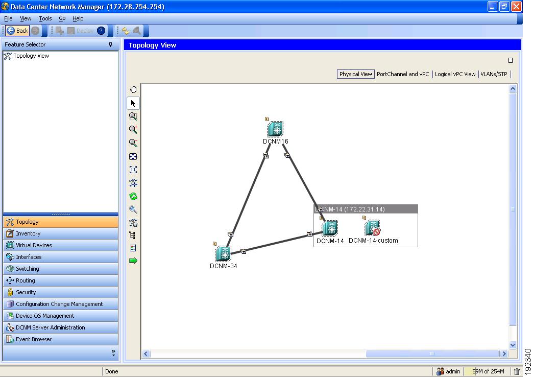
The Physical View (see Figure 9-1) shows the physical connections between discovered devices. This is the default topology view.
Figure 9-1 Physical View of the Topology Map
PortChannel and vPC
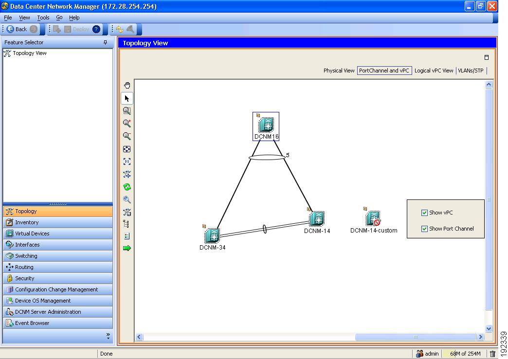
The PortChannel and vPC view (see Figure 9-2) shows all physical connections and all logical connections among discovered devices, including port channel links, virtual port channel (vPC) links, and vPC peer links. Physical links appear in gray in this view.
Figure 9-2 PortChannel and vPC View of the Topology Map
Logical vPC View
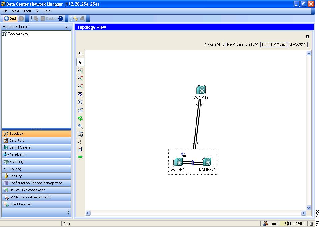
The Logical vPC View (see Figure 9-3) shows vPC links and vPC peer links among discovered devices, without showing the physical connections.
Figure 9-3 Logical vPC View of the Topology Map
VLANs/STP
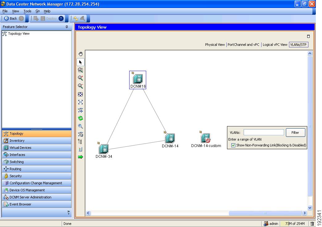
The VLANs/STP view (see Figure 9-4) shows VLANs configured among discovered devices.
Figure 9-4 VLANs/STP View of the Topology Map
Layouts
The topology map enables you to move devices to where you want them. You can save the layout so that the next time you use the topology map, devices are where you placed them. The DCNM client saves topology layouts as local user data on the computer that runs the DCNM client. When you are using the DCNM client, you do not have access to topology layouts that you saved on other computers or that you saved while logged in to the computer under a different username.
In addition to saved layouts, when you are using the Physical View, you can load one of the following layouts:
•![]() Hierarchical—Devices appear in levels that minimize the length of most connections. The top level has minimal crossed connections.
Hierarchical—Devices appear in levels that minimize the length of most connections. The top level has minimal crossed connections.
•![]() Grid—Devices appear in rows and columns, with no simplification of the appearance of connections.
Grid—Devices appear in rows and columns, with no simplification of the appearance of connections.
•![]() Spring—Device appear in locations determined by weighting the connections, which often produces a layout with minimal or no crossed connections.
Spring—Device appear in locations determined by weighting the connections, which often produces a layout with minimal or no crossed connections.
•![]() Tree—Devices appear in a tree unless connections create loops among the devices, in which case devices appear in a spanning tree, that is, a grid in which most of the connections follow the grid layout.
Tree—Devices appear in a tree unless connections create loops among the devices, in which case devices appear in a spanning tree, that is, a grid in which most of the connections follow the grid layout.
vPC Support
The topology map provides the following additional vPC-specific features:
•![]() vPC creation—You can launch the vPC Creation Wizard from the PortChannel and vPC view. See the "Launching the vPC Wizard" section.
vPC creation—You can launch the vPC Creation Wizard from the PortChannel and vPC view. See the "Launching the vPC Wizard" section.
•![]() Quick access to the vPC feature—You can access the configuration for a specific vPC from the PortChannel and vPC view or the Logical vPC View. See the "Managing a vPC" section.
Quick access to the vPC feature—You can access the configuration for a specific vPC from the PortChannel and vPC view or the Logical vPC View. See the "Managing a vPC" section.
•![]() vPC configuration inconsistency—You can see vPC links and vPC peer links that have configuration inconsistencies. You can open the Resolve Configuration Consistency dialog box from the topology map. See the "Finding and Resolving vPC Configuration Inconsistencies" section.
vPC configuration inconsistency—You can see vPC links and vPC peer links that have configuration inconsistencies. You can open the Resolve Configuration Consistency dialog box from the topology map. See the "Finding and Resolving vPC Configuration Inconsistencies" section.
Licensing Requirements for Topology
The following table shows the licensing requirements for this feature:
|
|
|
|---|---|
DCNM |
The Topology feature requires no license; however, the Logical vPC View of the topology map requires a LAN Enterprise license. Any feature not included in a license package is bundled with the Cisco DCNM and is provided at no charge to you. For information about obtaining and installing a DCNM LAN Enterprise license, see the "Installing Licenses" section on page 2-7. |
Prerequisites for Topology
Topology has the following prerequisites:
•![]() The topology map shows only devices that DCNM has discovered.
The topology map shows only devices that DCNM has discovered.
•![]() On devices shown in the topology map, CDP should be enabled both globally and specifically on interfaces used for device discovery.
On devices shown in the topology map, CDP should be enabled both globally and specifically on interfaces used for device discovery.
Guidelines and Limitations
Topology has the following configuration guidelines and limitations:
•![]() While the Topology feature is an unlicensed feature, you must have a LAN Enterprise license to manage nondefault VDCs that appears in the topology.
While the Topology feature is an unlicensed feature, you must have a LAN Enterprise license to manage nondefault VDCs that appears in the topology.
•![]() The Topology feature displays changes to the topology periodically as determined by the polling frequency for accounting and system logs. By default, the polling frequency is one minute. For more information, see the "Information About Auto-Synchronization with Devices" section on page 15-1.
The Topology feature displays changes to the topology periodically as determined by the polling frequency for accounting and system logs. By default, the polling frequency is one minute. For more information, see the "Information About Auto-Synchronization with Devices" section on page 15-1.
Using the Topology Feature
This section includes the following topics:
•![]() Understanding Device Icons and Links
Understanding Device Icons and Links
•![]() Showing, Hiding, and Using the Details Pane
Showing, Hiding, and Using the Details Pane
•![]() Finding and Resolving vPC Configuration Inconsistencies
Finding and Resolving vPC Configuration Inconsistencies
•![]() Accessing Other DCNM Features from the Topology Map
Accessing Other DCNM Features from the Topology Map
•![]() Moving Devices in the Topology Map
Moving Devices in the Topology Map
•![]() Reloading the Previously Saved Layout
Reloading the Previously Saved Layout
•![]() Exporting the Topology as a JPG Image
Exporting the Topology as a JPG Image
Opening the Topology Map
You can open the topology map to view the topology of discovered devices.
DETAILED STEPS
To view the topology, follow these steps:
Step 1 ![]() From the Feature Selector pane, choose Topology > Topology View.
From the Feature Selector pane, choose Topology > Topology View.
The topology map appears in the Contents pane. Buttons for each of the available topology views appear above the topology map.
Step 2 ![]() (Optional) If you want to change topology views, click the topology view name.
(Optional) If you want to change topology views, click the topology view name.
The topology map shows the view of the topology that you selected.
Step 3 ![]() (Optional) If you want to use a view-specific option, see the following table:
(Optional) If you want to use a view-specific option, see the following table:
Understanding Device Icons and Links
To understand the device icons and links shown in the topology map, you can open the legend. The legend presents information about the device icons and links shown in the currently selected topology view.
DETAILED STEPS
To open the legend, follow these steps:
Step 1 ![]() From the Feature Selector pane, choose Topology > Topology View.
From the Feature Selector pane, choose Topology > Topology View.
The topology map appears in the Contents pane. Buttons for each of the available topology views appear above the topology map.
Step 2 ![]() (Optional) If you want to change topology views, click the topology view name.
(Optional) If you want to change topology views, click the topology view name.
The topology map shows the view of the topology that you selected. The topology toolbar appears on the left side of the topology map.
Step 3 ![]() From the topology tool bar, click the
From the topology tool bar, click the  icon.
icon.
The Legend dialog box displays information about the device icons and links that may appear in the currently selected topology view.
Using the Viewing Tools
You can use the pan, select, zoom, and search tools to view the topology map.
The following table describes the viewing tools that are available in the topology toolbar, which is on the left side of the topology map.
|
|
|
|---|---|
|
Moves, or pans, the map. 1. 2. 3. 4. |
|
Allows you to select a device, link, or port icon. 1. 2. A balloon displays information about the icon that you clicked. |
|
Zooms to a specific portion of the map. 1. 2. |
|
Zooms in. Click the |
|
Zooms out. Click the |
|
Fit the entire topology of discovered devices within the topology map. Click the |
|
Resets the zoom to the default magnification. Click the |
|
Allows you to use the device search tool, so that you can search for a device by its name. 1. 2. 3. |
|
Opens the Legend dialog box. See the "Understanding Device Icons and Links" section. |
 Pan
Pan  Zoom in Rect
  Zoom In
  Zoom Out
  Fit to View
  Reset Zoom
  Search
Showing, Hiding, and Using the Details Pane
You can show or hide the Details pane within the topology map. When you are showing the Details pane, you can use the sections within the Details pane to learn about the devices and connections in the topology.
DETAILED STEPS
To show, hide, or the Details pane, follow these steps:
Step 1 ![]() From the Feature Selector pane, choose Topology > Topology View.
From the Feature Selector pane, choose Topology > Topology View.
The topology map appears in the Contents pane. The topology toolbar appears on the left side of the topology map.

Tip ![]() To see the names of topology toolbar icons, move the mouse pointer to the icon and wait briefly for the name of the icon to appear.
To see the names of topology toolbar icons, move the mouse pointer to the icon and wait briefly for the name of the icon to appear.
Step 2 ![]() To show or hide details, click the
To show or hide details, click the  icon.
icon.
When you choose to show details, the Details pane appears between the topology toolbar and the topology map.
Tip ![]() Ensure that the Select tool is selected. To select the Select tool, click the
Ensure that the Select tool is selected. To select the Select tool, click the  icon.
icon.
Step 3 ![]() To use the sections within the Details pane, see the following table:
To use the sections within the Details pane, see the following table:
Launching the vPC Wizard
From the topology map, you can launch the vPC wizard to create a vPC.
BEFORE YOU BEGIN
Determine which two devices you want to use as the vPC peer switches.
DETAILED STEPS
To launch the vPC wizard, follow these steps:
Step 1 ![]() From the Feature Selector pane, choose Topology > Topology View.
From the Feature Selector pane, choose Topology > Topology View.
The topology map appears in the Contents pane.
Step 2 ![]() Above the map, click PortChannel and vPC.
Above the map, click PortChannel and vPC.
The map shows the PortChannel and vPC view of the topology.
Step 3 ![]() From the topology toolbar, choose the icon.
From the topology toolbar, choose the icon.
Step 4 ![]() Click one device that you want to use as a vPC peer switch.
Click one device that you want to use as a vPC peer switch.
Step 5 ![]() Press and hold the Shift key.
Press and hold the Shift key.
Step 6 ![]() Click the device that you want to use as a vPC peer switch.
Click the device that you want to use as a vPC peer switch.
Step 7 ![]() Right-click either device and choose Launch vPC Wizard.
Right-click either device and choose Launch vPC Wizard.
The vPC Creation Wizard dialog box appears.
For more information about using this wizard, see the Cisco DCNM Interfaces Configuration Guide, Release 4.1.
Managing a vPC
From the topology map, you can access the vPC feature for a specific vPC link.
DETAILED STEPS
To manage a vPC, follow these steps:
Step 1 ![]() From the Feature Selector pane, choose Topology > Topology View.
From the Feature Selector pane, choose Topology > Topology View.
The topology map appears in the Contents pane.
Step 2 ![]() Above the map, click one of the following views:
Above the map, click one of the following views:
•![]() PortChannel and vPC
PortChannel and vPC
•![]() Logical vPC View
Logical vPC View
Step 3 ![]() Locate the vPC link for the vPC that you want to manage.
Locate the vPC link for the vPC that you want to manage.
Step 4 ![]() Use the step that applies to the view that you selected:
Use the step that applies to the view that you selected:
•![]() PortChannel and vPC—Right-click the ellipse on the vPC link and choose Manage vPC.
PortChannel and vPC—Right-click the ellipse on the vPC link and choose Manage vPC.
•![]() Logical vPC View—Right-click the vPC link and choose Manage vPC.
Logical vPC View—Right-click the vPC link and choose Manage vPC.
The vPC feature appears. The vPC that you want to manage is selected in the summary table.
For more information about the vPC feature, see the Cisco DCNM Interfaces Configuration Guide, Release 4.1.
Finding and Resolving vPC Configuration Inconsistencies
You can use the topology map to find vPCs that have configuration inconsistencies and open the Resolve Configuration Inconsistency dialog box.
DETAILED STEPS
To find and resolve vPC configuration inconsistencies, follow these steps:
Step 1 ![]() From the Feature Selector pane, choose Topology > Topology View.
From the Feature Selector pane, choose Topology > Topology View.
The topology map appears in the Contents pane.
Step 2 ![]() Above the map, click one of the following views:
Above the map, click one of the following views:
•![]() PortChannel and vPC
PortChannel and vPC
•![]() Logical vPC View
Logical vPC View
Step 3 ![]() Locate the vPC for which you want to resolve configuration inconsistencies.
Locate the vPC for which you want to resolve configuration inconsistencies.
If a vPC link has configuration inconsistencies, a red ellipse appears over the link. If you use the PortChannel and vPC view, vPC peer links with configuration inconsistencies also show a red ellipse.
Step 4 ![]() (Optional) If you want to resolve configuration inconsistencies now, do one of the following:
(Optional) If you want to resolve configuration inconsistencies now, do one of the following:
•![]() To resolve configuration inconsistencies for the vPC link and the vPC peer link, right-click the red ellipse on the vPC link and choose Launch Configuration Consistency.
To resolve configuration inconsistencies for the vPC link and the vPC peer link, right-click the red ellipse on the vPC link and choose Launch Configuration Consistency.
•![]() To resolve configuration inconsistencies for the vPC peer link only, right-click the red ellipse on the vPC link and choose Launch Configuration Consistency.
To resolve configuration inconsistencies for the vPC peer link only, right-click the red ellipse on the vPC link and choose Launch Configuration Consistency.
The Resolve Configuration Inconsistency dialog box opens.
For more information about using the Resolve Configuration Inconsistencies dialog box, see the Cisco DCNM Interfaces Configuration Guide, Release 4.1.
Accessing Other DCNM Features from the Topology Map
You can use the topology map to access other features for managed devices. From the topology map, you can access features that are found in the following Feature Selector drawers:
•![]() Inventory
Inventory
•![]() Virtual Devices
Virtual Devices
•![]() Interfaces
Interfaces
•![]() Routing
Routing
•![]() Switching
Switching
•![]() Security
Security
You can also use the topology map to access the Device Discovery feature.
DETAILED STEPS
To access a feature from the topology map, follow these steps:
Step 1 ![]() From the Feature Selector pane, choose Topology > Topology View.
From the Feature Selector pane, choose Topology > Topology View.
The topology map appears in the Contents pane. The topology toolbar appears on the left side of the topology map.

Note ![]() To see the names of topology toolbar icons, move the mouse pointer to the icon and wait briefly for the name of the icon to appear.
To see the names of topology toolbar icons, move the mouse pointer to the icon and wait briefly for the name of the icon to appear.
Step 2 ![]() If you want to access a DCNM feature for a specific managed device, do the following:
If you want to access a DCNM feature for a specific managed device, do the following:
a. ![]() Find the device in the topology map.
Find the device in the topology map.
b. ![]() Right-click the device and choose the feature that you want to configure.
Right-click the device and choose the feature that you want to configure.
The feature that you selected appears in the Contents pane. The device that you selected on the topology map is selected in the Summary table for the feature.
Step 3 ![]() If you want to access the Device Discovery feature, right-click a blank area on the map and choose Discover Devices.
If you want to access the Device Discovery feature, right-click a blank area on the map and choose Discover Devices.
The Device Discovery feature appears in the Contents pane.
Moving Devices in the Topology Map
You can move device icons that are shown in the topology map. The position of devices is shared by all the topology views, that is, if you move a device and then change to another topology view, the device remains where you moved it to.
You can also save the layout, which you can reload later if you make additional changes and want to revert to your last save. For more information, see the "Reloading the Previously Saved Layout" section.
The saved layout becomes the default layout that you see in the topology map when you start the DCNM client.
Note ![]() The DCNM client saves topology layouts as local user data on the computer that runs the DCNM client. When you are using the DCNM client, you do not have access to topology layouts that you saved on other computers or that you saved while logged in to the computer under a different username.
The DCNM client saves topology layouts as local user data on the computer that runs the DCNM client. When you are using the DCNM client, you do not have access to topology layouts that you saved on other computers or that you saved while logged in to the computer under a different username.
DETAILED STEPS
To move devices in the topology map, follow these steps:
Step 1 ![]() From the Feature Selector pane, choose Topology > Topology View.
From the Feature Selector pane, choose Topology > Topology View.
The topology map appears in the Contents pane. The topology toolbar appears on the left side of the topology map.
Note ![]() To see the names of topology toolbar icons, move the mouse pointer to the icon and wait briefly for the name of the icon to appear.
To see the names of topology toolbar icons, move the mouse pointer to the icon and wait briefly for the name of the icon to appear.
Step 2 ![]() From the topology toolbar, choose the icon.
From the topology toolbar, choose the icon.
Step 3 ![]() Find and move device icons as needed. To move an icon, click on the device icon, hold down the mouse button, drag the icon to the new location, and release the mouse button.
Find and move device icons as needed. To move an icon, click on the device icon, hold down the mouse button, drag the icon to the new location, and release the mouse button.
You can zoom and pan as needed to find icons. For more information, see the "Using the Viewing Tools" section.
Step 4 ![]() (Optional) If you want to save the changes to the device icon layout, click the
(Optional) If you want to save the changes to the device icon layout, click the  icon.
icon.
Loading a Layout
When you are using the Physical View, you can choose to load a layout. The position of devices is shared by all the topology views. This behavior allows you to use any of the layouts in all views by loading the layout in the Physical View and then choosing another view.
Note ![]() If you are using a different view than the Physical View, the
If you are using a different view than the Physical View, the  icon on the topology toolbar acts the same as the
  icon. For information about using the icon, see the "Reloading the Previously Saved Layout" section.
BEFORE YOU BEGIN
Determine which physical devices, if any, that you want to specify as core switches. When you load a layout other than a saved layout, core switches appear at the top of the topology map, devices that are one CDP hop from the core switches appear just below them.
DETAILED STEPS
To load a topology layout in Physical View, follow these steps:
Step 1 ![]() From the Feature Selector pane, choose Topology > Topology View.
From the Feature Selector pane, choose Topology > Topology View.
The topology map appears in the Contents pane. The topology toolbar appears on the left side of the topology map.
Note ![]() To see the names of topology toolbar icons, move the mouse pointer to the icon and wait briefly for the name of the icon to appear.
To see the names of topology toolbar icons, move the mouse pointer to the icon and wait briefly for the name of the icon to appear.
Step 2 ![]() (Optional) For each physical device that you want to appear at the top of the layout, right-click on the device icon and choose Make as Core Switch.
(Optional) For each physical device that you want to appear at the top of the layout, right-click on the device icon and choose Make as Core Switch.
Step 3 ![]() From the topology toolbar, click the icon.
From the topology toolbar, click the icon.
The Layout drop-down list appears.
Step 4 ![]() From the Layout drop-down list, select the layout that you want to load.
From the Layout drop-down list, select the layout that you want to load.
The Physical View of the topology map changes to the layout that you selected. Any devices that you specified as core switches appear at the top of the map, with devices that are one CDP hop away from the core switches appearing just below them.
Reloading the Previously Saved Layout
You can load the most recently saved layout. This feature allows you to undo changes to device placement that you have made since you last saved the layout.
Note ![]() The DCNM client saves topology layouts as local user data on the computer that runs the DCNM client. When you are using the DCNM client, you do not have access to topology layouts that you saved on other computers or that you saved while logged in to the computer under a different username.
The DCNM client saves topology layouts as local user data on the computer that runs the DCNM client. When you are using the DCNM client, you do not have access to topology layouts that you saved on other computers or that you saved while logged in to the computer under a different username.
DETAILED STEPS
To reload the most recent saved topology layout, follow these steps:
Step 1 ![]() From the Feature Selector pane, choose Topology > Topology View.
From the Feature Selector pane, choose Topology > Topology View.
The topology map appears in the Contents pane. The topology toolbar appears on the left side of the topology map.
Note ![]() To see the names of topology toolbar icons, move the mouse pointer to the icon and wait briefly for the name of the icon to appear.
To see the names of topology toolbar icons, move the mouse pointer to the icon and wait briefly for the name of the icon to appear.
Step 2 ![]() From the topology toolbar, choose the icon.
From the topology toolbar, choose the icon.
The topology map changes to the most recent layout that you saved.
Exporting the Topology as a JPG Image
You can export, or save, a JPG image of the topology map. The JPG image created shows only the portion of the topology that appears in the DCNM client at the moment that you save the JPG file.
DETAILED STEPS
To export the visible portion of the topology map as a JPG image, follow these steps:
Step 1 ![]() From the Feature Selector pane, choose Topology > Topology View.
From the Feature Selector pane, choose Topology > Topology View.
The topology map appears in the Contents pane. The topology toolbar appears on the left side of the topology map.
Note ![]() To see the names of topology toolbar icons, move the mouse pointer to the icon and wait briefly for the name of the icon to appear.
To see the names of topology toolbar icons, move the mouse pointer to the icon and wait briefly for the name of the icon to appear.
Step 2 ![]() View the portion of the topology map that you want to save. For more information, see the "Using the Viewing Tools" section.
View the portion of the topology map that you want to save. For more information, see the "Using the Viewing Tools" section.
Step 3 ![]() Arrange the device icons as desired. For more information, see the "Moving Devices in the Topology Map" section.
Arrange the device icons as desired. For more information, see the "Moving Devices in the Topology Map" section.
Step 4 ![]() From the topology toolbar, click the
From the topology toolbar, click the  icon.
icon.
A dialog box appears.
Step 5 ![]() Specify the location and filename of the JPG image and click Save.
Specify the location and filename of the JPG image and click Save.
The JPG image of the visible portion of the topology map is saved.
Related Documents
For additional information related to implementing Topology, see the following sections:
Feature History for Topology
Table 9-1 lists the release history for this feature.
 Feedback