Overview
This chapter describes how to configure a fabric with eBGP-based underlay.
It covers the following two use cases where eBGP-based fabric can be used:
The following sections are applicable for both use cases:
The documentation set for this product strives to use bias-free language. For the purposes of this documentation set, bias-free is defined as language that does not imply discrimination based on age, disability, gender, racial identity, ethnic identity, sexual orientation, socioeconomic status, and intersectionality. Exceptions may be present in the documentation due to language that is hardcoded in the user interfaces of the product software, language used based on RFP documentation, or language that is used by a referenced third-party product. Learn more about how Cisco is using Inclusive Language.
This chapter describes how to configure a typical spine-leaf based routed fabric with eBGP as the routing protocol of choice. This is the preferred deployment choice for Massively Scalable Data Center (MSDC) networks. Both Single-AS and Multi-AS options are supported. A routed fabric has no layer-2 stretch or subnet stretch across leafs. In other words, networks are localized to a pair of leafs or a rack, with leafs hosting the default gateway for the directly attached server workloads. Subnet advertisement across racks are communicated over eBGP via the spine thereby providing any-to-any reachability within the routed fabric.
This chapter describes how to configure a fabric with eBGP-based underlay.
It covers the following two use cases where eBGP-based fabric can be used:
The following sections are applicable for both use cases:
Choose Control > Fabric Builder.
The Fabric Builder screen appears. When you log in for the first time, the Fabrics section has no entries. After you create a fabric, it is displayed on the Fabric Builder screen, wherein a rectangular box represents each fabric.
Click Create Fabric. The Add Fabric screen appears.
The fields are explained:
Fabric Name - Enter the name of the fabric.
Fabric Template - From the drop-down menu, choose the Easy_Fabric_eBGP fabric template. The fabric settings for creating a standalone routed fabric comes up.
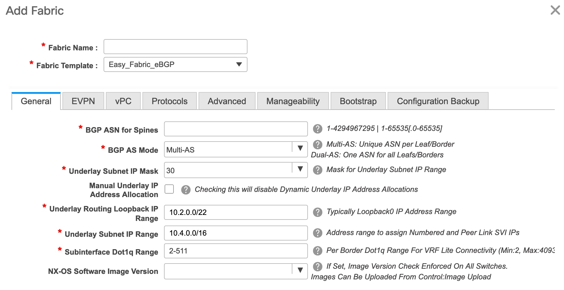
BGP ASN for Spines: Enter the BGP AS number of the fabric’s spine switches.
BGP AS Mode: Choose Multi-AS or Dual-AS.
In a Multi-AS fabric, the spine switches have a unique BGP AS number and each leaf switch has a unique AS number. If two leaf switches form a vPC switch pair, then they have the same AS number.
In a Dual-AS fabric, the spine switches have a unique BGP AS number and the leaf switches have a unique AS number.
The fabric is identified by the spine switch AS number.
Underlay Subnet IP Mask - Specifies the subnet mask for the fabric interface IP addresses.
Manual Underlay IP Address Allocation – Select this check box to disable Dynamic Underlay IP Address Allocations.
Underlay Routing Loopback IP Range: Specifies loopback IP addresses for the protocol peering.
Underlay Subnet IP Range: IP addresses for underlay P2P routing traffic between interfaces.
Subinterface Dot1q Range: Specifies the subinterface range when L3 sub interfaces are used.
NX-OS Software Image Version: Select an image from the drop-down list.
If you upload Cisco NX-OS software images through the image upload option, the uploaded images are listed in this field. If you select an image, the system checks if the switch has the selected version. If not, an error message is displayed. You can resolve the error by clicking on Resolve. The image management screen comes up and you can proceed with the ISSU option. Alternatively, you can delete the release number and save it later.
If you specify an image in this field, all switches in the fabric should run that image. If some devices do not run the image, a warning is prompted to perform an In-Service Software Upgrade (ISSU) to the specified image. Till all devices run the specified image, the deployment process will be incomplete.
If you want to deploy more than one type of software image on the fabric switches, don’t specify any image. If an image is specified, delete it.
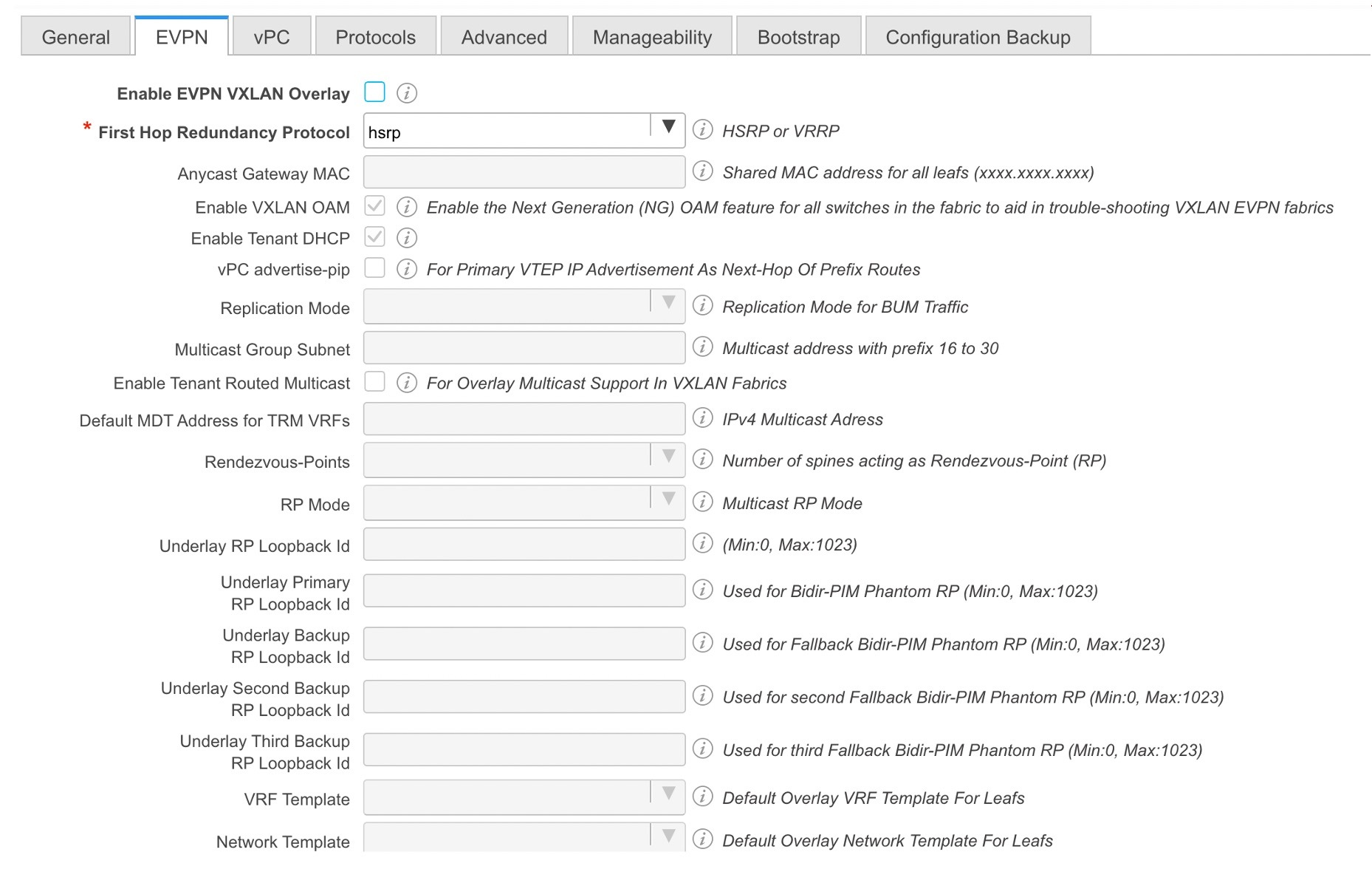
Click EVPN. The Enable EVPN VXLAN Overlay option must be explicitly disabled. Note that this checkbox is enabled by default. This option should be enabled only for use-cases where customers want to build an eBGP-underlay/overlay based VXLAN EVPN fabric.
Routed Fabric: In a Routed Fabric, once the IP reachability between the spine—leaf network has been established, you can easily create and deploy networks on the leafs using either HSRP or VRRP as the First-Hop Routing Protocol (FHRP) of choice. For more information, see Overview of Networks in a Routed Fabric.
When you create an eBGP Routed fabric, the fabric uses eBGP as the control plane to build intra-fabric connectivity. Links between spine and leaf switches are autoconfigured with point-to-point (p2p) numbered IP addresses with eBGP peering built on top.
Note that Routed_Network_Universal Template is only applicable to a Routed Fabric.
First Hop Redundancy Protocol: Specifies the FHRP protocol. Choose either hsrp or vrrp. This field is only applicable to a Routed Fabric.
 Note |
|
Click vPC. The fields in the tab are:
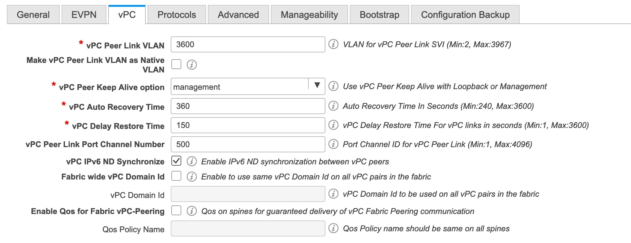
vPC Peer Link VLAN: VLAN used for the vPC peer link SVI.
Make vPC Peer Link VLAN as Native VLAN - Enables vPC peer link VLAN as Native VLAN.
vPC Peer Keep Alive option: Choose the management or loopback option. If you want to use IP addresses assigned to the management port and the management VRF, choose management. If you use IP addresses assigned to loopback interfaces (and a non-management VRF), choose loopback. If you use IPv6 addresses, you must use loopback IDs.
vPC Auto Recovery Time: Specifies the vPC auto recovery time-out period in seconds.
vPC Delay Restore Time: Specifies the vPC delay restore period in seconds.
vPC Peer Link Port Channel Number - Specifies the Port Channel ID for a vPC Peer Link. By default, the value in this field is 500.
vPC IPv6 ND Synchronize: Enables IPv6 Neighbor Discovery synchronization between vPC switches. The check box is enabled by default. Clear the check box to disable the function.
Click the Protocols tab. The fields in the tab are:
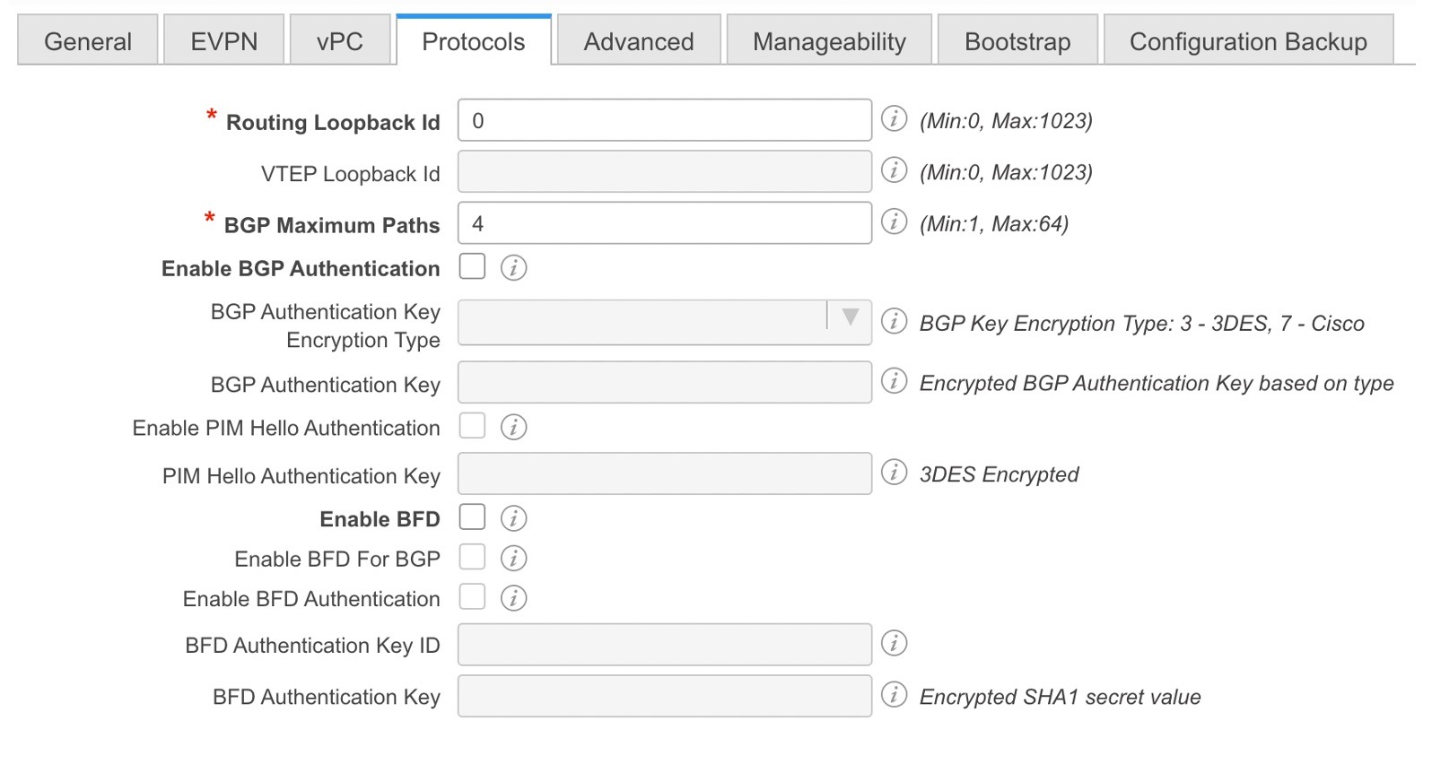
Routing Loopback Id - The loopback interface ID is populated as 0 by default. It is used as the BGP router ID.
BGP Maximum Paths - Specifies the BGP maximum paths.
Enable BGP Authentication: Select the check box to enable BGP authentication. Deselect the check box to disable it. If you enable this field, the BGP Authentication Key Encryption Type and BGP Authentication Key fields are enabled.
BGP Authentication Key Encryption Type: Choose the 3 for 3DES encryption type, or 7 for Cisco encryption type.
BGP Authentication Key: Enter the encrypted key based on the encryption type.
 Note |
Plain text passwords are not supported. Login to the switch, retrieve the encrypted key and enter it in the BGP Authentication Key field. Refer the Retrieving the Authentication Key section for details. |
Enable BFD: Select the check box to enable feature bfd on all switches in the fabric. This feature is valid only on IPv4 underlay and the scope is within a fabric.
From Cisco DCNM Release 11.3(1), BFD within a fabric is supported natively. The BFD feature is disabled by default in the Fabric Settings. If enabled, BFD is enabled for the underlay protocols with the default settings. Any custom required BFD configurations must be deployed via the per switch freeform or per interface freeform policies.
The following config is pushed after you select the Enable BFD check box:
feature bfd
 Note |
After you upgrade from DCNM Release 11.2(1) with BFD enabled to DCNM Release 11.3(1), the following configs are pushed on all P2P fabric interfaces: |
For information about BFD feature compatibility, refer your respective platform documentation and for information about the supported software images, see Compatibility Matrix for Cisco DCNM.
Enable BFD for BGP: Select the check box to enable BFD for the BGP neighbor. This option is disabled by default.
Enable BFD Authentication: Select the check box to enable BFD authentication. If you enable this field, the BFD Authentication Key ID and BFD Authentication Key fields are editable.
BFD Authentication Key ID: Specifies the BFD authentication key ID for the interface authentication.
BFD Authentication Key: Specifies the BFD authentication key.
For information about how to retrieve the BFD authentication parameters, see Retrieving the Encrypted BFD Authentication Key, in Cisco DCNM LAN Fabric Configuration Guide.
Click the Advanced tab. The fields in the tab are:
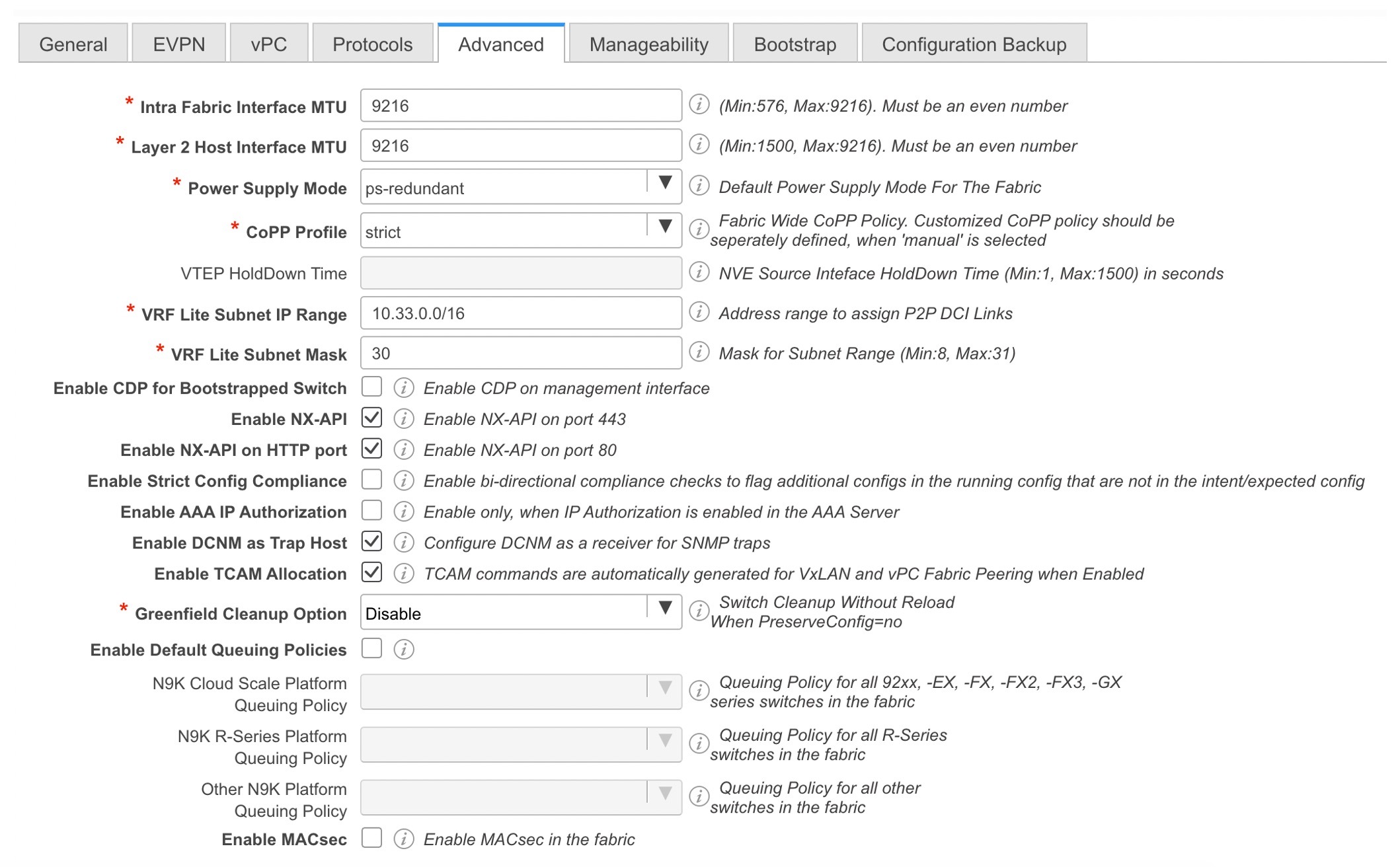
Intra Fabric Interface MTU - Specifies the MTU for the intra fabric interface. This value should be an even number.
Layer 2 Host Interface MTU - Specifies the MTU for the layer 2 host interface. This value should be an even number.
Power Supply Mode: Choose the appropriate power supply mode.
CoPP Profile: Choose the appropriate Control Plane Policing (CoPP) profile policy for the fabric. By default, the strict option is populated.
VRF Lite Subnet IP Range and VRF Lite Subnet Mask – These fields are populated with the DCI subnet details. Update the fields as needed.
Enable CDP for Bootstrapped Switch - Select the check box to enable CDP for bootstrapped switch.
Enable NX-API - Specifies enabling of NX-API on HTTPS. This check box is checked by default.
Enable NX-API on HTTP - Specifies enabling of NX-API on HTTP. Enable this check box and the Enable NX-API check box to use HTTP. This check box is checked by default. If you uncheck this check box, the applications that use NX-API and supported by Cisco DCNM, such as Endpoint Locator (EPL), Layer 4-Layer 7 services (L4-L7 services), VXLAN OAM, and so on, start using the HTTPS instead of HTTP.
 Note |
If you check the Enable NX-API check box and the Enable NX-API on HTTP check box, applications use HTTP. |
Enable Strict Config Compliance - Enable the Strict Config Compliance feature by selecting this check box.
For Strict Configuration Compliance, see Enhanced Monitoring and Monitoring Fabrics Guide.
 Note |
If Strict Config Compliance is enabled in a fabric, you cannot deploy Network Insights for Resources on Cisco DCNM. |
Enable AAA IP Authorization - Enables AAA IP authorization, when IP Authorization is enabled in the AAA Server.
Enable DCNM as Trap Host - Select this check box to enable DCNM as a trap host.
Enable TCAM Allocation: TCAM commands are automatically generated for VXLAN and vPC Fabric Peering when enabled.
Greenfield Cleanup Option: Enable the switch cleanup option for greenfield switches without a switch reload. This option is typically recommended only for the data center environments with the Cisco Nexus 9000v Switches.
Enable Default Queuing Policies: Check this check box to apply QoS policies on all the switches in this fabric. To remove the QoS policies that you applied on all the switches, uncheck this check box, update all the configurations to remove the references to the policies, and save and deploy. From Cisco DCNM Release 11.3(1), pre-defined QoS configurations are included that can be used for various Cisco Nexus 9000 Series Switches. When you check this check box, the appropriate QoS configurations are pushed to the switches in the fabric. The system queuing is updated when configurations are deployed to the switches. You can perform the interface marking with defined queuing policies, if required, by adding the required configuration to the per interface freeform block.
Review the actual queuing policies by opening the policy file in the template editor. From Cisco DCNM Web UI, choose Control > Template Library. Search for the queuing policies by the policy file name, for example, queuing_policy_default_8q_cloudscale. Choose the file and click the Modify/View template icon to edit the policy.
See the Cisco Nexus 9000 Series NX-OS Quality of Service Configuration Guide for platform specific details.
N9K Cloud Scale Platform Queuing Policy: Choose the queuing policy from the drop-down list to be applied to all Cisco Nexus 9200 Series Switches and the Cisco Nexus 9000 Series Switches that ends with EX, FX, and FX2 in the fabric. The valid values are queuing_policy_default_4q_cloudscale and queuing_policy_default_8q_cloudscale. Use the queuing_policy_default_4q_cloudscale policy for FEXes. You can change from the queuing_policy_default_4q_cloudscale policy to the queuing_policy_default_8q_cloudscale policy only when FEXes are offline.
N9K R-Series Platform Queuing Policy: Choose the queuing policy from the drop-down list to be applied to all Cisco Nexus switches that ends with R in the fabric. The valid value is queuing_policy_default_r_series.
Other N9K Platform Queuing Policy: Choose the queuing policy from the drop-down list to be applied to all other switches in the fabric other than the switches mentioned in the above two options. The valid value is queuing_policy_default_other.
Leaf Freeform Config: Add CLIs that should be added to switches that have the Leaf, Border, and Border Gateway roles.
Spine Freeform Config - Add CLIs that should be added to switches with a Spine, Border Spine, and Border Gateway Spine roles.
Intra-fabric Links Additional Config - Add CLIs that should be added to the intra-fabric links.
Click the Manageability tab.
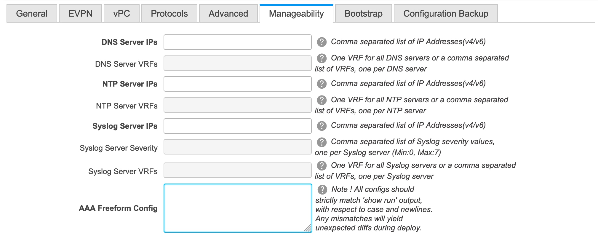
The fields in this tab are:
DNS Server IPs - Specifies the comma separated list of IP addresses (v4/v6) of the DNS servers.
DNS Server VRFs - Specifies one VRF for all DNS servers or a comma separated list of VRFs, one per DNS server.
NTP Server IPs - Specifies comma separated list of IP addresses (v4/v6) of the NTP server.
NTP Server VRFs - Specifies one VRF for all NTP servers or a comma separated list of VRFs, one per NTP server.
Syslog Server IPs – Specifies the comma separated list of IP addresses (v4/v6) IP address of the syslog servers, if used.
Syslog Server Severity – Specifies the comma separated list of syslog severity values, one per syslog server. The minimum value is 0 and the maximum value is 7. To specify a higher severity, enter a higher number.
Syslog Server VRFs – Specifies one VRF for all syslog servers or a comma separated list of VRFs, one per syslog server.
AAA Freeform Config – Specifies the AAA freeform configs.
If AAA configs are specified in the fabric settings, switch_freeform PTI with source as UNDERLAY_AAA and description as “AAA Configurations” will be created.
Click the Bootstrap tab.
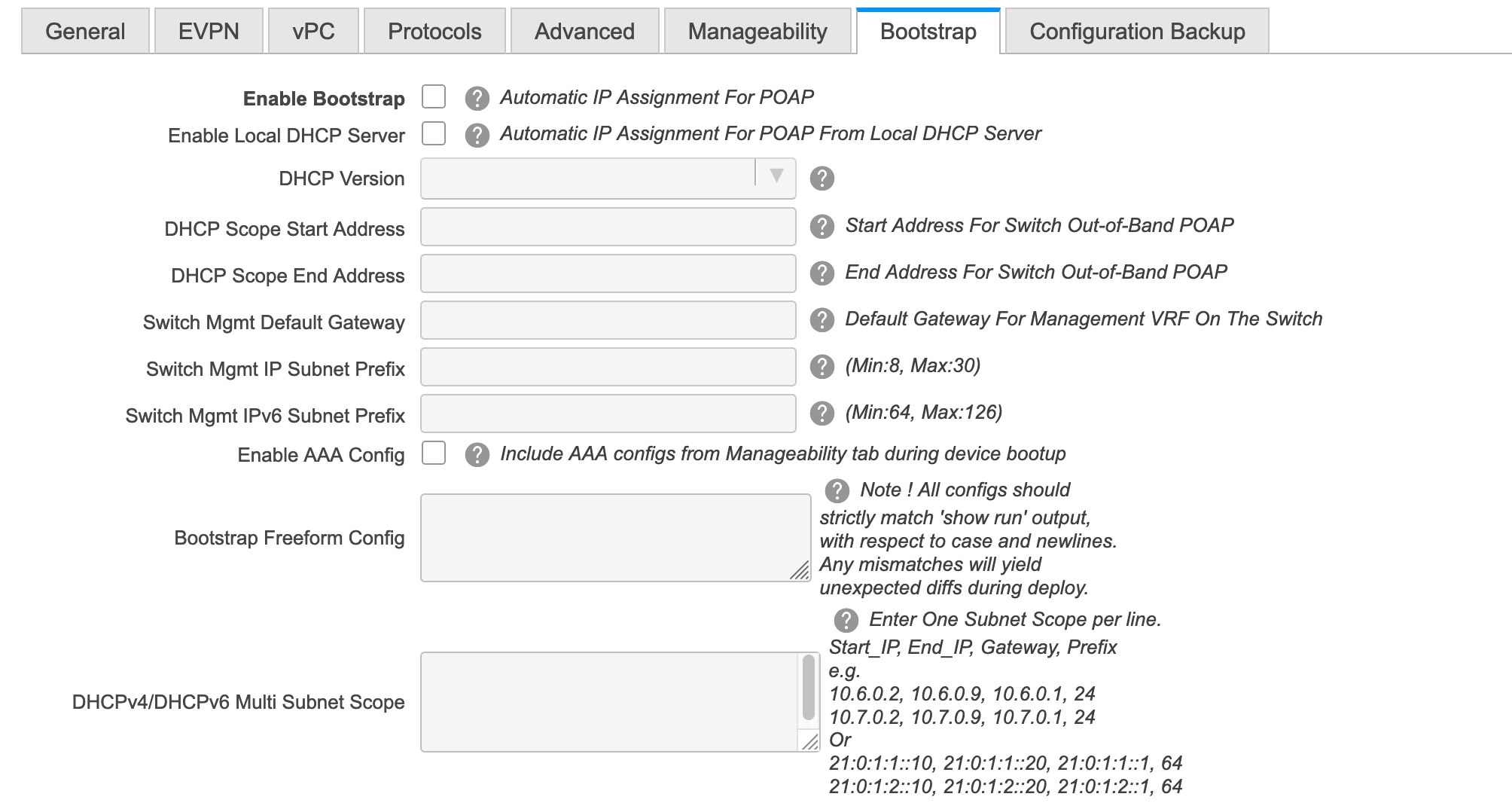
Enable Bootstrap - Select this check box to enable the bootstrap feature.
After you enable bootstrap, you can enable the DHCP server for automatic IP address assignment using one of the following methods:
External DHCP Server: Enter information about the external DHCP server in the Switch Mgmt Default Gateway and Switch Mgmt IP Subnet Prefix fields.
Local DHCP Server: Enable the Local DHCP Server check box and enter details for the remaining mandatory fields.
Enable Local DHCP Server - Select this check box to initiate enabling of automatic IP address assignment through the local DHCP server. When you select this check box, the DHCP Scope Start Address and DHCP Scope End Address fields become editable.
If you do not select this check box, DCNM uses the remote or external DHCP server for automatic IP address assignment.
DHCP Version – Select DHCPv4 or DHCPv6 from this drop-down list. When you select DHCPv4, the Switch Mgmt IPv6 Subnet Prefix field is disabled. If you select DHCPv6, the Switch Mgmt IP Subnet Prefix is disabled.
 Note |
Cisco DCNM IPv6 POAP is not supported with Cisco Nexus 7000 Series Switches. Cisco Nexus 9000 and 3000 Series Switches support IPv6 POAP only when switches are either L2 adjacent (eth1 or out-of-band subnet must be a /64) or they are L3 adjacent residing in some IPv6 /64 subnet. Subnet prefixes other than /64 are not supported. |
DHCP Scope Start Address and DHCP Scope End Address - Specifies the first and last IP addresses of the IP address range to be used for the switch out of band POAP.
Switch Mgmt Default Gateway: Specifies the default gateway for the management VRF on the switch.
Switch Mgmt IP Subnet Prefix: Specifies the prefix for the Mgmt0 interface on the switch. The prefix should be between 8 and 30.
DHCP scope and management default gateway IP address specification - If you specify the management default gateway IP address 10.0.1.1 and subnet mask 24, ensure that the DHCP scope is within the specified subnet, between 10.0.1.2 and 10.0.1.254.
Switch Mgmt IPv6 Subnet Prefix - Specifies the IPv6 prefix for the Mgmt0 interface on the switch. The prefix should be between 112 and 126. This field is editable if you enable IPv6 for DHCP.
Enable AAA Config – Select this check box to include AAA configs from the Manageability tab during device bootup.
Bootstrap Freeform Config - (Optional) Enter additional commands as needed. For example, if you are using AAA or remote authentication related configurations, you need to add these configurations in this field to save the intent. After the devices boot up, they contain the intent defined in the Bootstrap Freeform Config field.
Copy-paste the running-config to a freeform config field with correct indentation, as seen in the running configuration on the NX-OS switches. The freeform config must match the running config. For more information, see Resolving Freeform Config Errors in Switches in Enabling Freeform Configurations on Fabric Switches.
DHCPv4/DHCPv6 Multi Subnet Scope - Specifies the field to enter one subnet scope per line. This field is editable after you check the Enable Local DHCP Server check box.
The format of the scope should be defined as:
DHCP Scope Start Address, DHCP Scope End Address, Switch Management Default Gateway, Switch Management Subnet Prefix
For example: 10.6.0.2, 10.6.0.9, 10.6.0.1, 24
Click the Configuration Backup tab. The fields on this tab are:

Hourly Fabric Backup: Select the check box to enable an hourly backup of fabric configurations and the intent.
You can enable an hourly backup for fresh fabric configurations and the intent as well. If there is a configuration push in the previous hour, DCNM takes a backup.
Intent refers to configurations that are saved in DCNM but yet to be provisioned on the switches.
Scheduled Fabric Backup: Check the check box to enable a daily backup. This backup tracks changes in running configurations on the fabric devices that are not tracked by configuration compliance.
Scheduled Time: Specify the scheduled backup time in a 24-hour format. This field is enabled if you check the Scheduled Fabric Backup check box.
Select both the check boxes to enable both back up processes.
The backup process is initiated after you click Save.
 Note |
Hourly and scheduled backup processes happen only during the next periodic configuration compliance activity, and there can be a delay of up to an hour. To trigger an immediate backup, do the following:
|
You can also initiate the fabric backup in the fabric topology window. Click Backup Now in the Actions pane.
Click Save after filling and updating relevant information.
Deploy the leaf underlay policies on all leaf switches at once, since they have a common AS number.
Brownfield migration is not supported for eBGP fabrics.
You cannot change the leaf switch AS number after it is created and the Save & Deploy operation is executed. You need to delete the leaf_bgp_asn policy and execute the Save & Deploy operation to remove BGP configuration related to this AS first. Then, you can add the leaf_bgp_asn policy with the new AS number.
If you want to switch between Multi-AS and Dual-AS modes, remove all manually added BGP policies (including leaf_bgp_asn on the leaf switch and the ebgp overlay policies), and execute the Save & Deploy operation before the mode change.
The supported roles are leaf, spine, and border leaf.
On the border device, VRF-Lite is supported with manual mode.
You must apply policies on the leaf and spine switches for a functional fabric.
Switches in each fabric are unique, and hence, each switch can only be added to one fabric.
Click the Add Switches option from the Actions panel to add switches to the fabric created in DCNM. The Inventory Management screen comes up. The screen contains two tabs, one for discovering existing switches and the other for discovering new switches. Both options are explained.
Additionally, you can pre-provision switches and interfaces. For more information, see Pre-provisioning a Device and Pre-provisioning an Ethernet Interface.
After clicking on Add Switches, use the Discover Existing Switches tab to add one or more existing switches into the fabric. In this case, a switch with known credentials and a pre-provisioned IP address, is added to the fabric. The IP address (Seed IP), administrator username, and password (Username and Password fields) of the switch are provided as the input by a user. The Preserve Config knob is set to yes by default. This is the option that a user would select for a brownfield import of a device into the fabric. For a greenfield import where the device configuration will be cleaned up as part of the import process, the user should set the Preserve Config knob to no.
 Note |
Easy_Fabric_eBGP does not support brownfield import of a device into the fabric. |
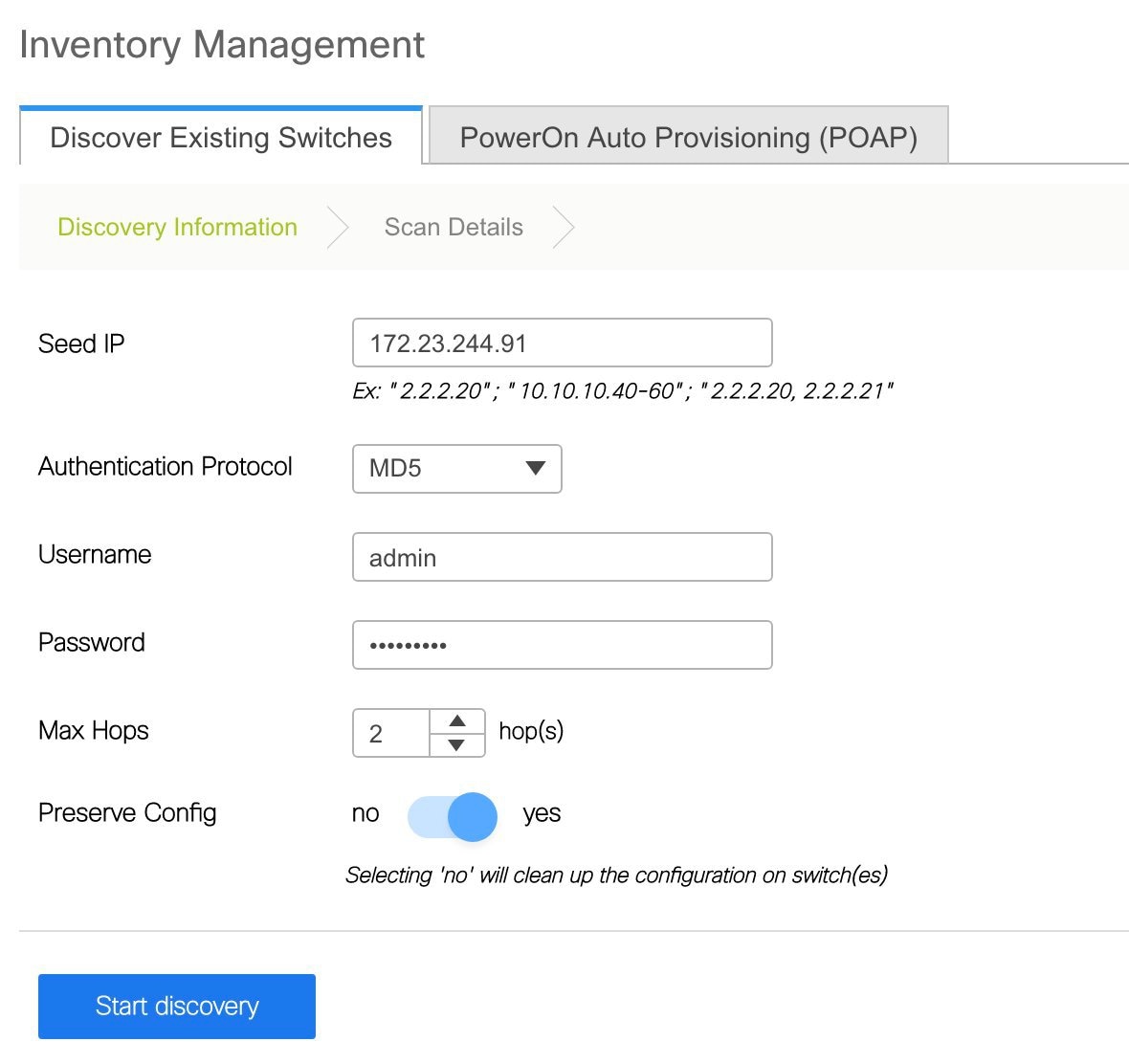
Click Start discovery. The Scan Details window comes up shortly. Since the Max Hops field was populated with 2 (by default), the switch with the specified IP address (leaf-91) and switches two hops from that switch, are populated in the Scan Detailsresult.
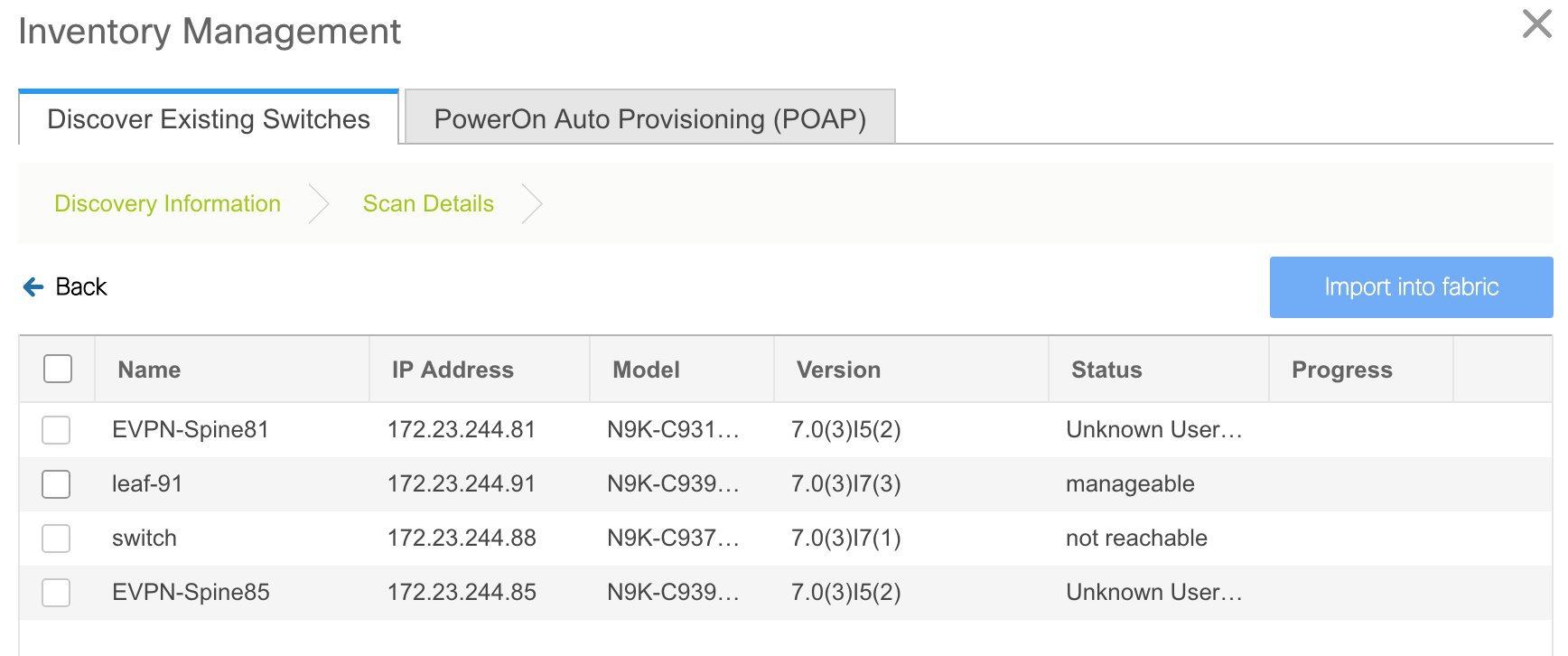
If the DCNM was able to perform a successful shallow discovery to a switch, the status will show up as Manageable. Select the check box next to the appropriate switch(es) and click Import into fabric.
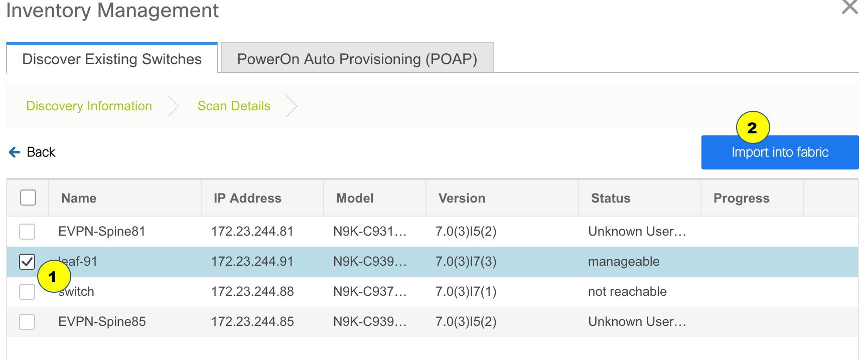
Though this example describes the discovery of one switch, multiple switches can be discovered at once.
The switch discovery process is initiated. The Progress column displays progress for all the selected switches. It displays done for each switch on completion.
 Note |
You must not close the screen (and try to add switches again) until all selected switches are imported or an error message comes up. If an error message comes up, close the screen. The fabric topology screen comes up. The error messages are displayed at the top right part of the screen. Resolve the errors wherever applicable and initiate the import process again by clicking Add Switches in the Actions panel. |
DCNM discovers all the switches, and the Progress column displays done for all switches, close the screen. The Standalone fabric topology screen comes up again. The switch icons of the added switches are displayed in it.
 Note |
You will encounter the following errors during switch discovery sometimes. |
Click Refresh topology to view the latest topology view.
When all switches are added and roles assigned to them, the fabric topology contains the switches and connections between them.

After discovering the devices, assign an appropriate role to each device. For this purpose, tight click the device, and use the Set role option to set the appropriate role. Alternatively, the tabular view may be employed to assign the same role to multiple devices at one go.
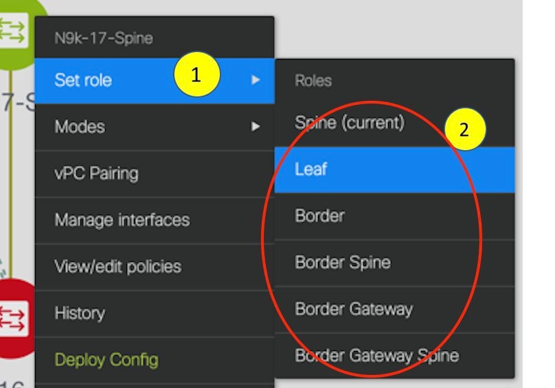
If you choose the Hierarchical layout for display (in the Actions panel), the topology automatically gets aligned as per role assignment, with the leaf devices at the bottom, the spine devices connected on top of them, and the border devices at the top.
Assign vPC switch role - To designate a pair of switches as a vPC switch pair, right-click the switch and choose the vPC peer switch from the list of switches.
AAA server password - During fabric creation, if you have entered AAA server information (in the Manageability tab), you must update the AAA server password on each switch. Else, switch discovery fails.
When a new vPC pair is created and deployed successfully using Cisco DCNM, one of the peers might be out-of-sync for the no ip redirects CLI even if the command exists on the switch. This out-of-sync is due to a delay on the switch to display the CLI in the running configuration, which causes a diff in the configuration compliance. Re-sync the switches in the Config Deployment window to resolve the diff.
Click Save & Deploy at the top right part of the screen.
The template and interface configurations form the underlay network configuration on the switches. Also, freeform CLIs that were entered as part of fabric settings (leaf and spine switch freeform configurations entered in the Advanced tab) are deployed. For more details on freeform configurations, refer Enabling Freeform Configurations on Fabric Switches.
Configuration Compliance: If the provisioned configurations and switch configurations do not match, the Status column displays out-of-sync. For example, if you enable a function on the switch manually through a CLI, then it results in a configuration mismatch.
To ensure configurations provisioned from DCNM to the fabric are accurate or to detect any deviations (such as out-of-band changes), DCNM’s Configuration Compliance engine reports and provides necessary remediation configurations.
When you click Save & Deploy, the Config Deployment window appears.
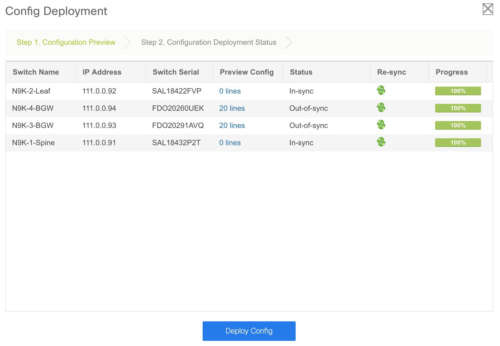
If the status is out-of-sync, it suggests that there is inconsistency between the DCNM and configuration on the device.
The Re-sync button is displayed for each switch in the Re-sync column. Use this option to resynchronize DCNM state when there is a large scale out-of-band change, or if configuration changes do not register in the DCNM properly. The re-sync operation does a full CC run for the switch and recollects “show run” and “show run all” commands from the switch. When you initiate the re-sync process, a progress message is displayed on the screen. During the re-sync, the running configuration is taken from the switch. The Out-of-Sync/In-Sync status for the switch is recalculated based on the intent defined in DCNM.
Click the Preview Config column entry (updated with a specific number of lines). The Config Preview screen comes up.
The PendingConfig tab displays the pending configurations for successful deployment.
The Side-by-sideComparison tab displays the current configurations and expected configurations together.
In DCNM 11, multi-line banner motd configuration is supported. Multi-line banner motd configuration can be configured in DCNM with freeform configuration policy, either per switch using switch_freeform, or per fabric using leaf/spine freeform configuration. Note that after the multi-line banner motd is configured, deploy the policy by executing the Save & Deploy option in the (top right part of the) fabric topology screen. Else, the policy may not be deployed properly on the switch. The banner policy is only to configure single-line banner configuration. Also, you can only create one banner related freeform configuration/policy. Multiple policies for configuring banner motd are not supported.
Close the screen.
In the Configuration Deployment screen, click Deploy Config at the bottom part of the screen to initiate pending configuration onto the switch. The Status column displays FAILED or SUCCESS state. For a FAILED status, investigate the reason for failure to address the issue.
After successful configuration provisioning (when all switches display a progress of 100%), close the screen.
The fabric topology is displayed. The switch icons turn green to indicate successful configuration.
If a switch icon is in red color, it indicates that the switch and DCNM configurations are not in sync.When deployment is pending on a switch, the switch is displayed in blue color. The pending state indicates that there is a pending deployment or pending recomputation. You can click on the switch and review the pending deployments using Preview or Deploy Config options, or click Save & Deploy to recompute the state of the switch.
 Note |
If there are any warning or errors in the CLI execution, a notification will appear in the Fabric builder window. Warnings or errors that are auto-resolvable have the Resolve option. |
When a leaf switch boots up after a switch reload or RMA operation, DCNM provisions configurations for the switch and FEX devices connected to it. Occasionally, FEX connectivity comes up after DCNM provisions FEX (host interface) configurations, resulting in a configuration mismatch. To resolve the mismatch, click Save & Deploy again in the fabric topology screen.
From Cisco NX-OS Release 11.4(1), if you uncheck the FEX check box in the Topology window, FEX devices are hidden in the Fabric Builder topology window as well. To view FEX in Fabric Builder, you need to check this check box. This option is applicable for all fabrics and it is saved per session or until you log out of DCNM. If you log out and log in to DCNM, the FEX option is reset to default, that is, enabled by default. For more information, see Show Panel.
An example of the Deploy Config option usage is for switch-level freeform configurations. Refer Enabling Freeform Configurations on Fabric Switches for details.
When a new Cisco NX-OS device is powered on, typically that device has no startup configuration or any configuration state for that matter. Consequently, it powers on with NX-OS and post initialization, goes into a POAP loop. The device starts sending out DHCP requests on all the interfaces that are up including the mgmt0 interface.
As long as there is IP reachability between the device and the DCNM, the DHCP request from the device, will be forwarded to the DCNM. For easy day-0 device bring-up, the bootstrap options should be enabled in the Fabric Settings as mentioned earlier.
With bootstrap enabled for the fabric, the DHCP request coming from the device will be serviced by the DCNM. The temporary IP address allocated to the device by the DCNM will be employed to learn basic information about the switch including the device model, device NX-OS version, etc.
In the DCNM GUI, go to a fabric (Click Control > Fabric Builder and click a fabric). The fabric topology is displayed.
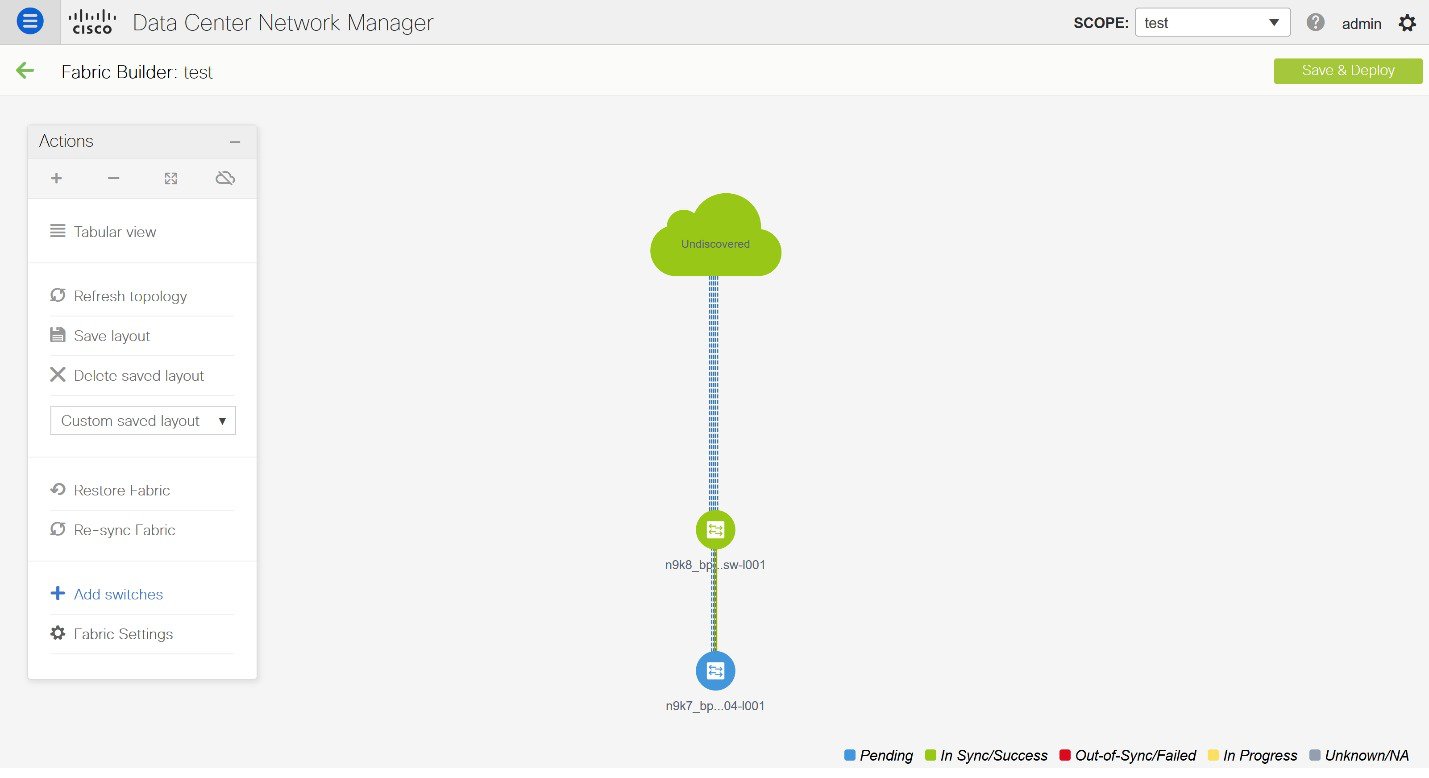
Go to the fabric topology window and click the Add switches option from the Actions panel. The Inventory Management window comes up.
Click the POAP tab.
As mentioned earlier, DCNM retrieves the serial number, model number, and version from the device and displays them on the Inventory Management along window. Also, an option to add the IP address, hostname, and password are made available. If the switch information is not retrieved, refresh the window.
 Note |
|
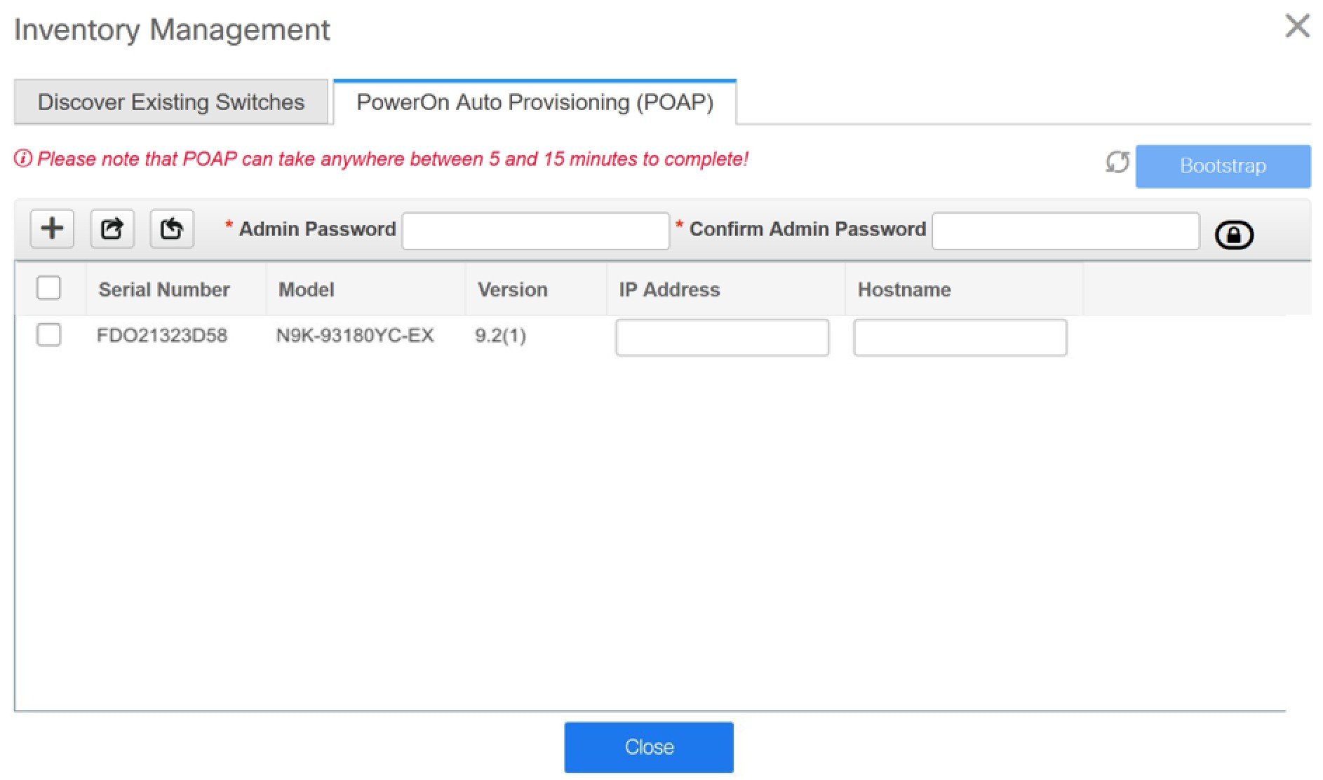
Select the checkbox next to the switch and enter the switch credentials: IP address and host name.
Based on the IP address of your device, you can either add the IPv4 or IPv6 address in the IP Address field.
Beginning with Release 11.2(1), you can provision devices in advance. To pre-provision devices, refer to Pre-provisioning a Device.
In the Admin Password and Confirm Admin Password fields, enter and confirm the admin password.
This admin password is applicable for all the switches displayed in the POAP window.
 Note |
If you do not want to use admin credentials to discover switches, you can instead use the AAA authentication, that is, RADIUS or TACACS credentials for discovery only. |
(Optional) Use discovery credentials for discovering switches.
Click the Add Discovery Credentials icon to enter the discovery credentials for switches.
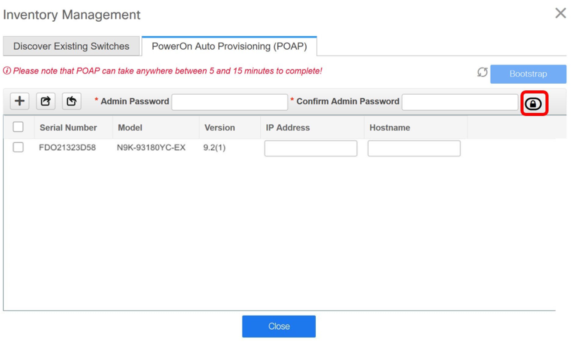
In the Discovery Credentials window, enter the discovery credentials such as discovery username and password.
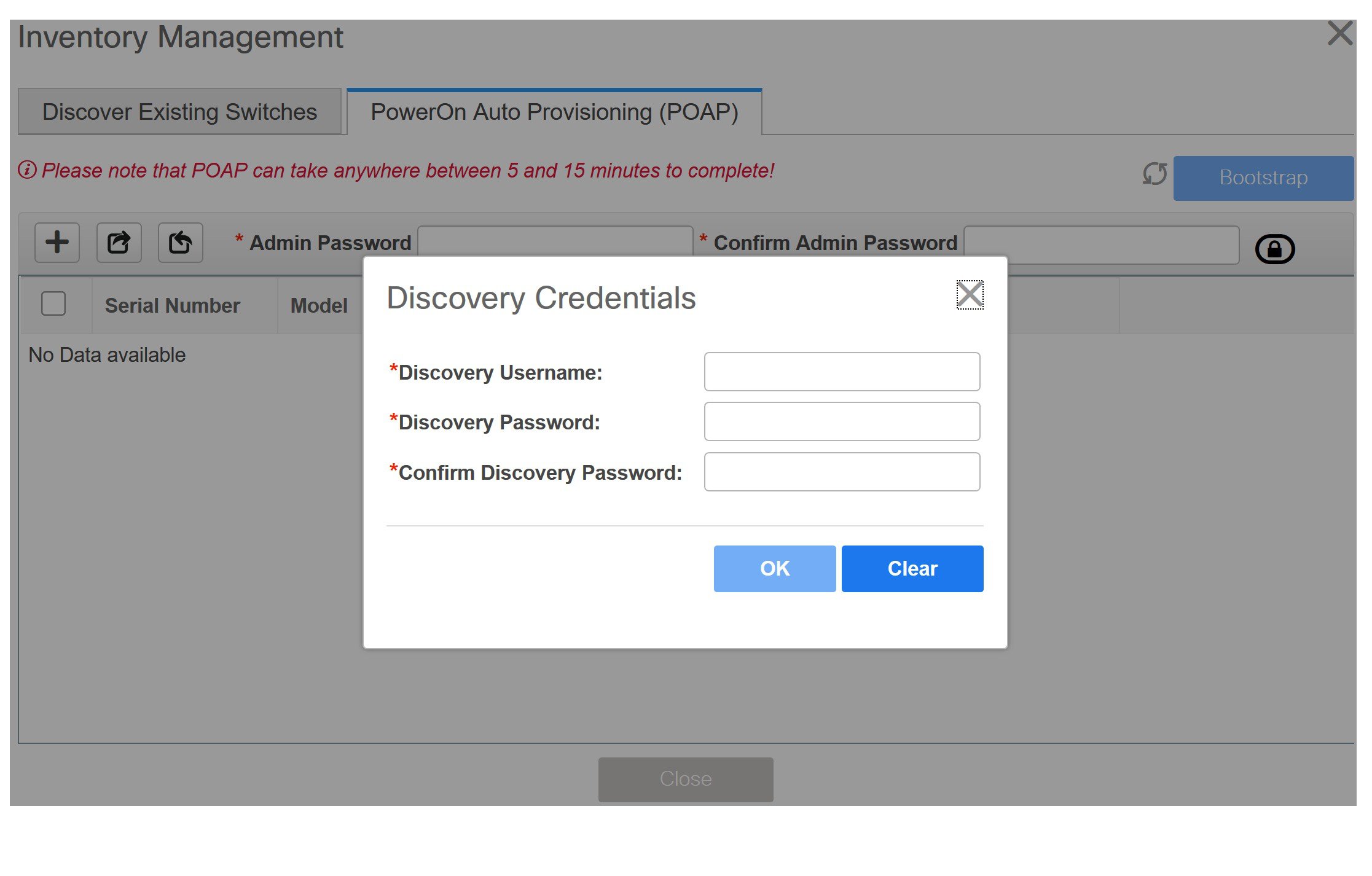
Click OK to save the discovery credentials.
If the discovery credentials are not provided, DCNM uses the admin user and password to discover switches.
Click Bootstrap at the top right part of the screen.
DCNM provisions the management IP address and other credentials to the switch. In this simplified POAP process, all ports are opened up.
Click Refresh Topology to get updated information. The added switch goes through the POAP cycle. Monitor and check the switch for POAP completion.
After the added switch completes POAP, the fabric builder topology page is refreshed with the added switch thereby depicting its discovered physical connections. Set the appropriate role for the switch followed by a Save & Deploy operation at the fabric level. The Fabric Settings, switch role, the topology etc. are evaluated by the Fabric Builder and the appropriate intended configuration for the switch is generated as part of the Save operation. The pending configuration will provide a list of the configurations that need to be deployed to the new switch in order to bring it IN-SYNC with the intent.
 Note |
For any changes on the fabric that results in the Out-of-Sync, then you must deploy the changes. The process is the same as explained in the Discovering Existing Switches section. During fabric creation, if you have entered AAA server information (in the Manageability tab), you must update the AAA server password on each switch. Else, switch discovery fails. |
After the pending configurations are deployed, the Progress column displays 100% for all switches.
Click Close to return to the fabric builder topology.
Click Refresh Topology to view the update. All switches must be in green color indicating that they are functional.
The switch and the link are discovered in DCNM. Configurations are built based on various policies (such as fabric, topology, and switch generated policies). The switch image (and other required) configurations are enabled on the switch.
In the DCNM GUI, the discovered switches can be seen in the Standalone fabric topology. Up to this step, the POAP is completed with basic settings. You must setup interfaces through the Control > Interfaces option for any additional configurations, but not limited to the following:
vPC pairing.
Breakout interfaces.
Port channels, and adding members to ports.
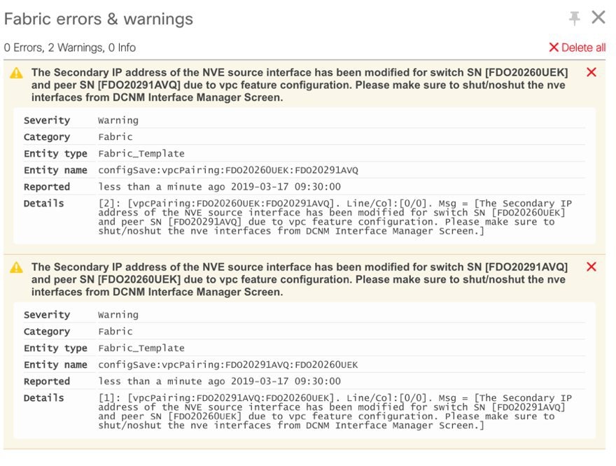
When you enable or disable a vPC pairing/un-pairing or the advertise-pip option, or update Multi-Site configuration, you should use the Save & Deploy operation. At the end of the operation, an error prompts you to configure the shutdown or no shutdown command on the nve interface. A sample error screenshot when you enable a vPC setup:
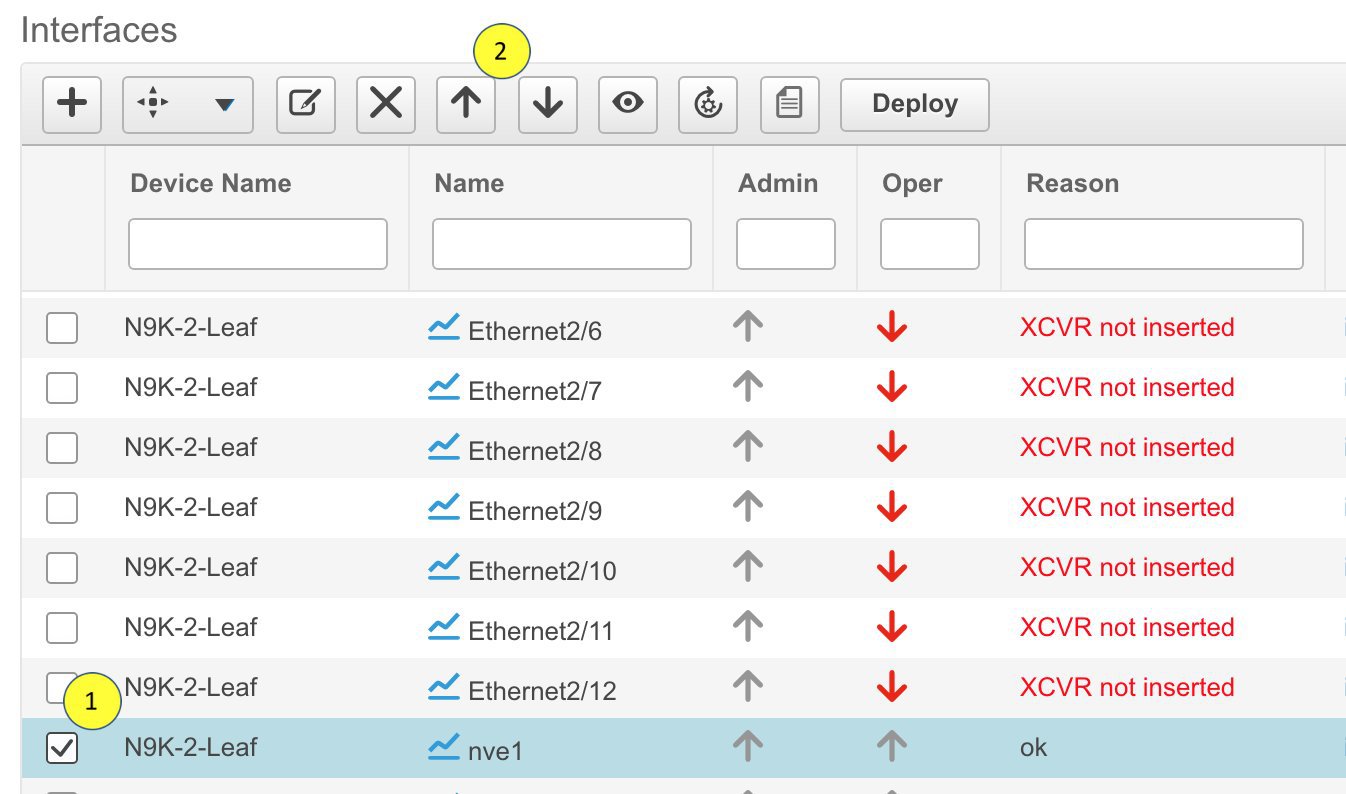
To resolve, go to the Control > Interfaces screen and deploy the Shutdown operation on the nve interface followed by a No Shutdown configuration. This is depicted in the figure below where the up arrow corresponds to a No Shutdown operation while a down arrow corresponds to a Shutdown operation.
You can right-click the switch to view various options:
Set Role - Assign a role to the switch (Spine, Border Gateway, and so on).
 Note |
|
Modes - Maintenance and Active/Operational modes.
vPC Pairing - Select a switch for vPC and then select its peer.
You can create a virtual link for a vPC pair or change the existing physical link to a virtual link for a vPC pair.
Manage Interfaces - Deploy configurations on the switch interfaces.
View/Edit Policies - See switch policies and edit them as required.
History - View per switch deployment and policy change history.
The Policy Change History tab lists the history of policies along with the users who made the changes like add, update, or delete.

Under the Policy Change History tab, for a policy, click Detailed History under the Generated Config column to view the generated config before and after.
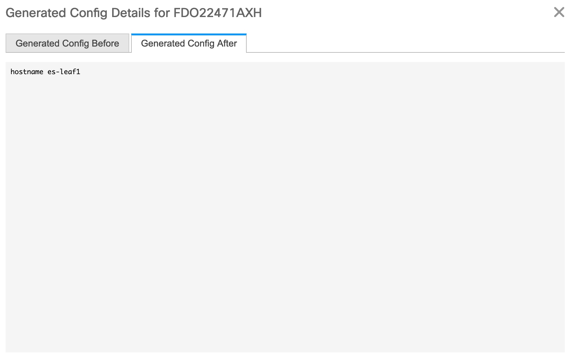
The following table provides the summary of generated config before and after for Policy Template Instances (PTIs).
| PTI Operations | Generated Config Before | Generated Config After |
| Add | Empty | Contains the config |
| Update | Contains config before changes | Contains config after changes |
| Mark-Delete | Contains the config to be removed. | Contains the config to be removed with colour change. |
| Delete | Contains the config | Empty |
 Note |
When a policy or profile template is applied, an instance is created for each application of the template, which is known as Policy Template Instance or PTI. |
Preview Config - View the pending configuration and the side-by-side comparison of the running and expected configuration.
Deploy Config - Deploy per switch configurations.
Discovery - You can use this option to update the credentials of the switch, reload the switch, rediscover the switch, and remove the switch from the fabric.
The new fabric is created, the fabric switches are discovered in DCNM, the underlay configuration provisioned on those switches, and the configurations between DCNM and the switches are synced. The remaining tasks are:
Provision interface configurations such as vPCs, loopback interface, and subinterface configurations. [Refer Interfaces].
Create networks and deploy them on the switches. [Refer Creating and Deploying Networks and VRFs].
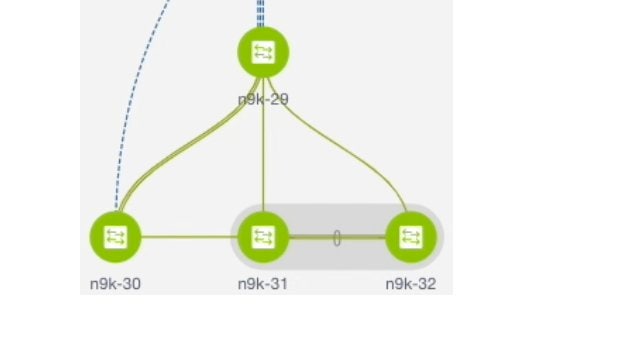
The topology shows a Routed fabric enabled with eBGP as the routing protocol for distributing reachability information. In DCNM, a fabric with the Easy_Fabric_eBGP template is created. One spine switch (n9k-29) and three leaf switches (n9k-30, and vPC switch pair n9k-31 and n9k-32) are imported to it.
The two different types of fabrics are:
Creating a Multi-AS mode fabric: In a Multi-AS mode fabric, spine switches have a common BGP AS number and each leaf switch has a unique BGP AS number. Use the same steps for Dual-AS to Multi-AS mode fabric conversion.
Creating a Dual-AS mode fabric: Alternate steps are mentioned for Dual-AS mode fabric creation. Use the same steps for Multi-AS to a Dual-AS mode fabric conversion.
In a Dual-AS fabric, all spine switches have a common BGP AS number and all leaf switches have a common BGP AS number (differing from the spine switches’ BGP AS number). You must deploy policies as explained in the next section.
To deploy fabric underlay eBGP policy, you must manually add the leaf_bgp_asn policy on each leaf switch to specify the BGP AS number used on the switch. Implementing the Save & Deploy operation afterward will generate eBGP peering over the physical interface between the leaf and spine switches to exchange underlay reachability information.
Click Tabular View at the left part of the screen. The Switches | Links screen comes up.
Select the leaf switch (n9k-30 check box for example) and click View/Edit Policies. The View/Edit Policies screen comes up.
 Note |
When you create an eBGP fabric in the Dual-AS mode (or change from the Multi-AS mode to Dual-AS mode), select all leaf switches since they have a common BGP AS number. |
Click Add. The Add Policy screen comes up.
From the Policy drop down box, select leaf_bgp_asn and enter the BGP AS number in the BGP AS # field.
Click Save.
Repeat the procedure for the vPC switches. For a vPC switch pair, select both switches and apply the leaf_bgp_asn policy.
 Note |
This step is not needed if you create a fabric in the Dual-AS mode (or converting to the Dual-AS mode), and you have assigned a BGP AS number to all of them, as explained in the earlier steps. |
Close the View/Edit Policies window.
In the topology screen, click Save & Deploy at the top right part of the screen.
Deploy configurations as per the Config Deployment wizard.
From Cisco DCNM Release 11.3(1), you can create a top-down network configuration for a routed fabric using DCNM. A routed fabric is run in one VRF, which is the default VRF. Note that creating VRFs manually is disabled for a routed fabric. Since the fabric is an IPv4 fabric, IPv6 address within the network is not supported. In a routed fabric, a network can only be attached to one device or a pair of vPC devices, unless it is a Layer 2 only network.
 Note |
A routed fabric network configuration will not be put under a config-profile. |
When the eBGP fabric is configured as Routed Fabric (EVPN is disabled), at the fabric level, you can select the first hop redundancy protocol (FHRP) for host traffic to be either HSRP or VRRP. HSRP is the default value.
For a vPC pair, DCNM generates network level HSRP or VRRP configuration based on the fabric setting. If HSRP is chosen, each network is configured with one HSRP group, and the HSRP VIP address. By default, all the networks will share the same HSRP group number allocated by DCNM, while you can overwrite it per network. VRRP support is similar to HSRP.
HSRP authentication or VRRP authentication is not supported. If you want to use authentication, you can enter the applicable commands in the network freeform config.
vPC peer gateway can be used to minimize peer link usage in the case that some third-party devices ignore the HSRP virtual-MAC and use the ARP packet source MAC for ARP learning. In Routed fabric mode, DCNM generates vPC peer gateway command for VPC devices.
For an eBGP fabric, changing between routed fabric type and EVPN fabric type, or HSRP and VRRP, is not allowed with the presence of networks and VRFs. You need to undeploy and delete these networks and VRFs before changing the fabric type or FHRP. For more information, see Undeploying Networks for the Standalone Fabric and Undeploying VRFs for the Standalone Fabric.
After the upgrade from DCNM Release 11.2(1) to 11.3(1), if the fabric was running in Routed Fabric mode previously, the default fabric values such as FHRP protocol and network VLAN range are internally set for a Routed Fabric. You need to edit the fabric settings if you want to configure different values. Before deploying a network configuration, you need to update the FHRP protocol fabric setting and click Save & Deploy.
| Step 1 |
Navigate to Control > Networks. |
||||
| Step 2 |
From the SCOPE drop-down list, choose a routed fabric. |
||||
| Step 3 |
Click the Add button in the Networks window to create a network. 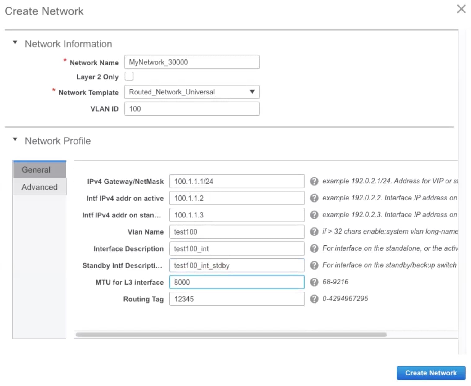 Network Name: Specifies the name of the network. The network name should not contain any white spaces or special characters except underscore (_) and hyphen (-). Layer 2 Only: Optional. Specifies whether the network is a Layer 2 only network. FHRP configuration is not generated in a Layer 2 only network.
Network Template: Select the Routed_Network_Universal template. VLAN ID: Optional. Specifies the corresponding tenant VLAN ID for the network. Network Profile section contains the General and Advanced tabs. General tab IPv4 Gateway/NetMask: Specifies the IPv4 gateway address with subnet. Intf IPv4 addr on active: Specifies the IPv4 interface address on an active device in a vPC pair. This field is applicable only when you are creating and deploying a network for a vPC pair of devices. Intf IPv4 addr on standby: Specifies the IPv4 interface address on a standby/backup device in a vPC pair. This field is applicable only when you are creating and deploying a network for a vPC pair of devices.
The following fields under the General tab are optional: Vlan Name: Specifies the VLAN name. Interface Description: Specifies the description for the interface. Standby Intf Description: Specifies the description for the standby interface in a vPC pair. MTU for the L3 interface: Enter the MTU for Layer 3 interfaces. Routing Tag: Specifies the routing tag that is associated with each gateway IP address prefix. Advanced tab: This tab is applicable only when you are creating and deploying a network for a vPC pair of devices. 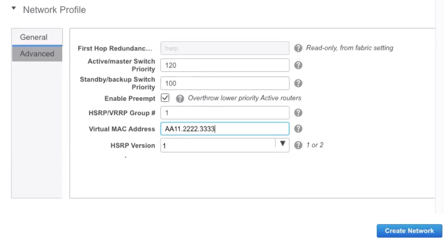 First Hop Redundancy Protocol: A read-only field that specifies FHRP selected in the fabric settings. Active/master Switch Priority:Specifies the priority of the active or master device. Standby/backup Switch Priority: Specifies the priority of the standby or backup device. The default value is 100. Note that this default value is not displayed when you preview the network configuration before deployment. Enable Preempt: Specifies whether the standby/backup device can preempt an active device. HSRP/VRRP Group #: Specifies the HSRP or VRRP group number. By default, HSRP group number is 1. Virtual MAC Address: Optional. Specifies the virtual MAC address. By default, VMAC is internally generated based on the HSRP group number (0000.0c9f.f000 + group number). The virtual MAC address is only applicable when hsrp is selected in the fabric settings. HSRP Version: Specifies the HSRP version. The default value is 1. The HSRP version field is only applicable for HSRP. |
||||
| Step 4 |
Click Create Network. |
||||
| Step 5 |
In the Networks window, select the check box next to a network and click Continue.
|
||||
| Step 6 |
Select a device or a vPC pair to deploy a network.
|
||||
| Step 7 |
In the Network Attachment window, for a vPC pair, assign the active state for a device. Enter true under the isActive column for an active device and false for a standby device. Click Save. 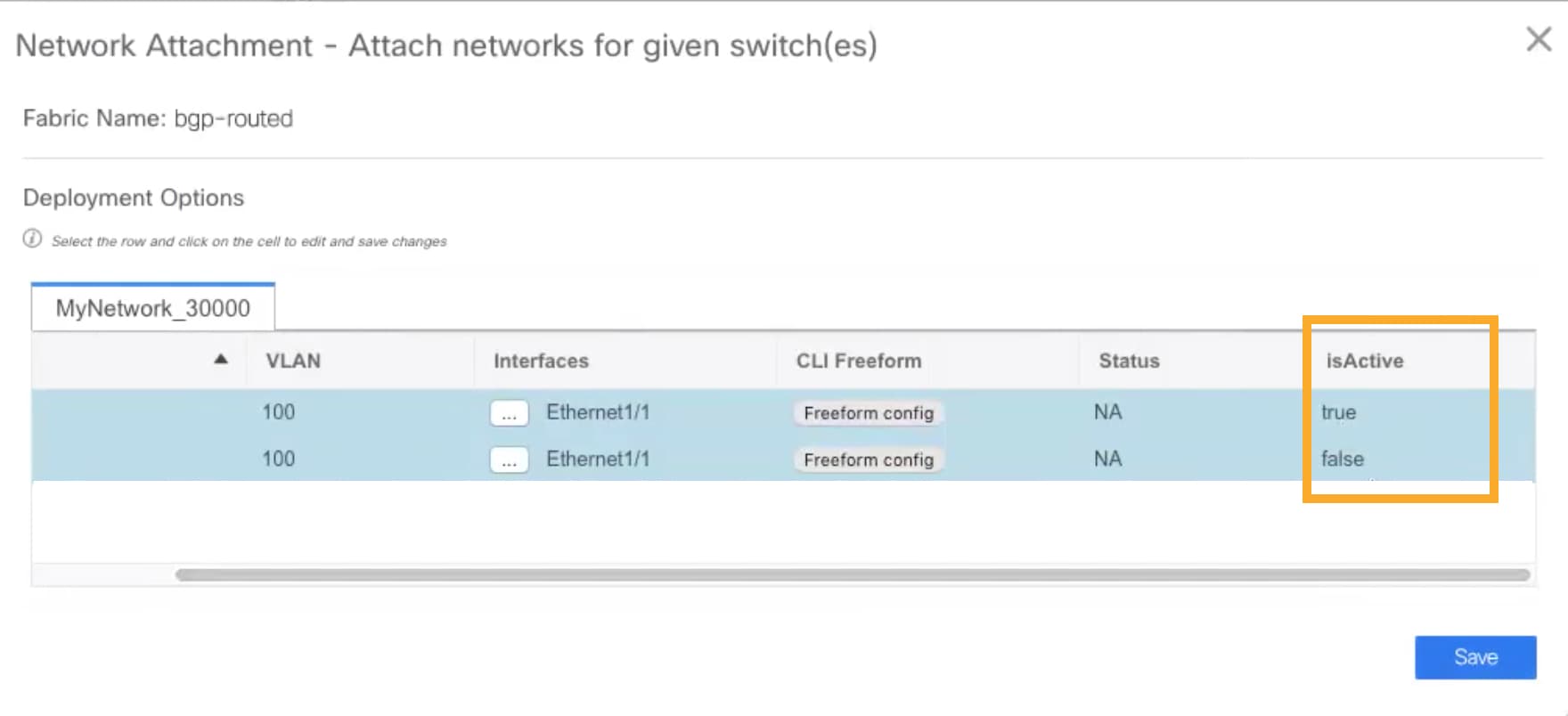
|
||||
| Step 8 |
(Optional) Click the Preview icon to preview the configs that will be deployed on devices. The Preview Configuration window is displayed. 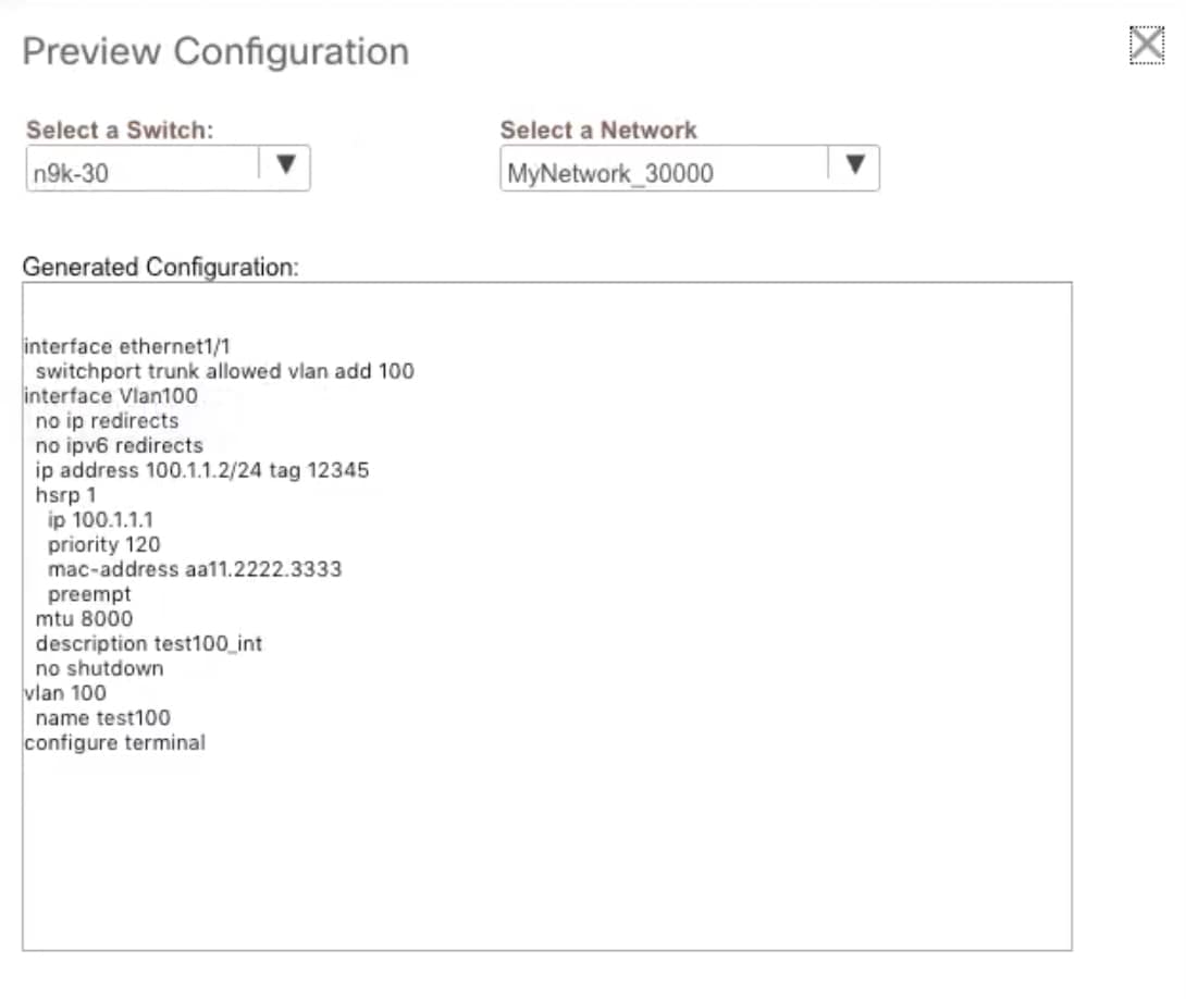 |
||||
| Step 9 |
Click the Deploy button in the Network / VRF Deployment window. You can also deploy the network by navigating to the Fabric Builder window and clicking the Deploy button. |
From DCNM Release 11.3(1), you can use an inter-fabric link to connect a route fabric to an edge router. This link configures an IP address on the physical interface and establish eBGP peering with the edge router on default vrf. The BGP configuration includes advertising default route to leaf switches.
 Note |
The Fabric Monitor Mode check box in the external fabric settings can be unchecked. Unchecking the Fabric Monitor Mode check box enables DCNM to deploy configurations to the external fabric. For more information, see Creating an External Fabric. |
| Step 1 |
Navigate to Control > Fabric Builder. |
||
| Step 2 |
Click a routed a fabric in the Fabric Builder window. |
||
| Step 3 |
Click Tabular view in the Actions panel that is displayed at the left part of the window. |
||
| Step 4 |
Click the Links tab. |
||
| Step 5 |
Click the Add icon to add a link. The Link Management – Add Link window is displayed. 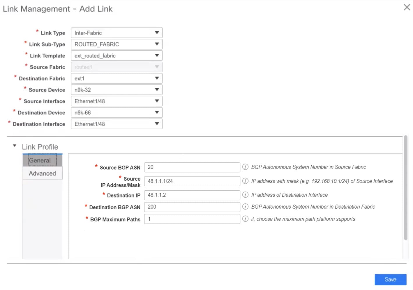 Link Type – Choose Inter-Fabric to create an inter-fabric connection between two fabrics, via their border switches or edge routers. Link Sub-Type – This field populates the IFC type. Choose ROUTED_FABRIC from the drop-down list. Link Template: The link template is populated. The templates are autopopulated with corresponding pre-packaged default templates that are based on your selection. For a routed fabric, the ext_routed_fabric template is populated. Source Fabric - This field is prepopulated with the source fabric name. Destination Fabric - Choose the destination fabric from this drop-down box. Source Device and Source Interface - Choose the source device and Ethernet or port channel interface that connects to the destination device. Only device with the border role can be chosen. Destination Device and Destination Interface—Choose the destination device and Ethernet or port channel interface that connects to the source device. Based on the selection of the source device and source interface, the destination information is autopopulated based on Cisco Discovery Protocol information, if available. There is an extra validation performed to ensure that the destination external device is indeed part of the destination fabric. General tab in the Link Profile section. BGP Local ASN: In this field, the AS number of the leaf is autopopulated if you have created and applied the leaf_bgp_asn policy. IP Address/Mask: Fill up this field with the IP address of the source interface that connects to the destination device. BGP Neighbor IP: Fill up this field with the IP address of the destination interface. BGP Neighbor ASN: In this field, the AS number of the destination device is autopopulated. BGP Maximum Paths: Specifies the maximum supported BGP paths. The Advanced tab contains the following optional fields: Source Interface Description and Destination Interface Description – Describe the links for later use. After Save & Deploy, this description will reflect in the running configuration. Source Interface Freeform CLIs and Destination Interface Freeform CLIs: Enter the freeform configurations specific to the source and destination interfaces. You should add the configurations as displayed in the running configuration of the switch, without indentation. For more information, refer to Enabling Freeform Configurations on Fabric Switches. |
||
| Step 6 |
Click Save to finish adding a link. |
||
| Step 7 |
Click the Back icon to navigate back to the Fabric Builder window. |
||
| Step 8 |
Right-click the device which is connecting to the edge router in the external fabric, and select Deploy Config. |
||
| Step 9 |
In the Config Deployment window, click Deploy Config. |
||
| Step 10 |
Navigate to the external fabric in the Fabric Builder window, and click Tabular view in the Actions panel. Click the Links tab to see all the links for the external fabric. You can see the inter-fabric link that has been created.
|
||
| Step 11 |
Click the Back icon twice to navigate back to the Fabric Builder window. |
||
| Step 12 |
Click the external fabric connecting to the routed fabric. |
||
| Step 13 |
Right-click the device which is connecting to the routed fabric, and select Deploy Config. |
||
| Step 14 |
In the Config Deployment window, click Deploy Config. |
You must manually add the eBGP overlay policy for overlay peering. DCNM provides the eBGP leaf and spine overlay peering policy templates that you can manually add to the leaf and spine switches to form the EVPN overlay peering.
Add the ebgp_overlay_spine_all_neighbor policy on the spine switch n9k-29. This policy can be deployed on all spine switches at once, since they share the same field values.
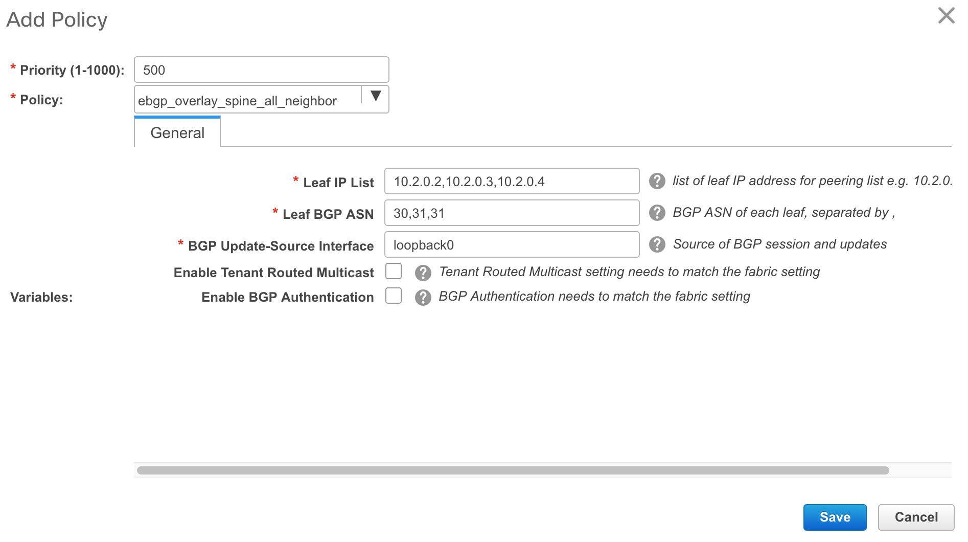
The fields on the screen are:
Leaf IP List - IP addresses of the connected leaf switch routing loopback interfaces.
10.2.0.2 is the loopback 0 peering IP address of leaf switch n9k-30. 10.2.0.3 and 10.2.0.4 are the IP addresses of the vPC switch pair n9k-31 and n9k-32.
Leaf BGP ASN – The BGP AS numbers of the leaf switches. Note that the AS number of vPC switches is the same, 31.
 Note |
When you create fabric in the Dual-AS mode, (or convert to Dual-AS mode), you must update this field with the common BGP AS number all the leaf switches belong to. |
BGP Update-Source Interface – This is the source interface of the BGP update. You can use loopback0 in this field, that is, the loopback interface for underlay routing.
Enable Tenant Routed Multicast – Select the checkbox to enable TRM for handling overlay multicast traffic. TRM enabling must match the fabric setting.
Enable BGP Authentication – Select the checkbox to enable BGP authentication.
The BGP authentication must match the fabric setting. Refer the Retrieving the Authentication Key section to know more about BGP authentication.
Add the ebgp_overlay_leaf_all_neighbor policy on all the leaf switches, to establish eBGP overlay peering towards the spine switch. This policy can be deployed on all leaf switches at once, since they share the same field values.

The fields on the screen are:
Spine IP List – IP addresses of the spine switch routing loopback interfaces.
10.2.0.1 is the loopback 0 peering IP address of spine switch n9k-29.
BGP Update-Source Interface – This is the source interface of the BGP update. You can use loopback0 in this field, that is, the loopback interface for underlay routing.
Enable Tenant Routed Multicast – Select the checkbox to enable TRM for handling overlay multicast traffic. TRM enabling must match the fabric setting.
Enable BGP Authentication – Select the checkbox to enable BGP authentication.
The BGP authentication must match the fabric setting. Refer the Retrieving the Authentication Key section to know more about BGP authentication.
Click Save & Deploy at the top right part of the screen, and deploy configurations as per the Config Deployment wizard. Or, use the View/Edit Policy option to select the policy and click Push Config to deploy the configuration.
The steps for overlay networks and VRFs provisioning are:
Create networks and VRFs for the fabric.
Deploy the networks and VRFs on the fabric switches.
 Note |
The undeployment and deletion of overlay networks and VRFs are explained after the explanation of deployment. Finally, creation of external fabrics and fabric extensions from VXLAN to external fabrics are documented. |
You can navigate to the networks and VRFs window through any of the following options:
From the home page: Click the Networks & VRFs button in the Cisco DCNM Web UI landing page.
From the Control menu: From the home page of the Cisco DCNM Web UI, choose Control > Fabrics > Networks to navigate to the Networks window. Choose Control > Fabrics > VRFs to navigate to the VRFs window.
From a fabric topology window: Right-click anywhere in the fabric topology window. Choose Overlay View > VRF View or Overlay View > Network View, accordingly. This option is applicable only for switch fabrics, easy fabrics, and MSD fabrics.
You can toggle between the network view and VRF view in both the windows by clicking the VRF View or Network View button. When you are in the networks or VRFs window, ensure you choose the appropriate fabric from the Scope drop-down list before you create any networks or VRFs.
Click Control > Networks from the main menu.
The Networks screen comes up. The SCOPE drop down box (at the top right part of the screen) lists all fabrics managed by the DCNM instance, in alphabetical order. You can choose the correct fabric from SCOPE. When you select a fabric, the Networks screen refreshes and lists networks of the selected fabric.

Click Control > VRFs from the main menu.
The VRFs screen comes up. The SCOPE drop down box (at the top right part of the screen) lists all fabrics managed by the DCNM instance, in alphabetical order. You can choose the correct fabric from SCOPE. When you select a fabric, the VRFs screen refreshes and lists VRFs of the selected fabric.

 Note |
The Networks or VRFs windows are applicable only for the Easy or MSD fabrics. |
Click Control > Networks (under Fabrics submenu).
The Networks screen comes up.
Choose the correct fabric from SCOPE. When you select a fabric, the Networks screen refreshes and lists networks of the selected fabric.

Click the + button at the top left part of the screen (under Networks) to add networks to the fabric. The Create Network screen comes up. Most of the fields are autopopulated.
The fields in this screen are:
Network ID and Network Name: Specifies the Layer 2 VNI and name of the network. The network name should not contain any white spaces or special characters except underscore (_) and hyphen (-). The corresponding Layer 3 VNI (or VRF VNI) is generated along with VRF creation.
VRF Name: Allows you to select the Virtual Routing and Forwarding (VRF).
When no VRF is created, this field appears blank. If you want to create a new VRF, click the + button. The VRF name should not contain any white spaces or special characters except underscore (_), hyphen (-), and colon (:).
Layer 2 Only: Specifies whether the network is Layer 2 only.
Network Template: A universal template is autopopulated. This is only applicable for leaf switches.
Network Extension Template: A universal extension template is autopopulated. This allows you to extend this network to another fabric. The methods are VRF Lite, Multi Site, and so on. The template is applicable for border leaf switches and BGWs.
VLAN ID: Specifies the corresponding tenant VLAN ID for the network.
Network Profile section contains the General and Advanced tabs.
General tab
IPv4 Gateway/NetMask: Specifies the IPv4 address with subnet.
 Note |
If the same IP address is configured in the IPv4 Gateway and IPv4 Secondary GW1 or GW2 fields of the network template, DCNM does not show an error, and you will be able to save this configuration. However, after the network configuration is pushed to the switch, it would result in a failure as the configuration is not allowed by the switch. |
IPv6 Gateway/Prefix: Specifies the IPv6 address with subnet.
Specify the anycast gateway IP address for transporting the L3 traffic from a server belonging to MyNetwork_30000 and a server from another virtual network. By default the anycast gateway IP address is the same for MyNetwork_30000 on all switches of the fabric that have the presence of the network.
VLAN Name - Enter the VLAN name.
Interface Description: Specifies the description for the interface. This interface is a switch virtual interface (SVI).
MTU for the L3 interface - Enter the MTU for Layer 3 interfaces.
IPv4 Secondary GW1 - Enter the gateway IP address for the additional subnet.
IPv4 Secondary GW2 - Enter the gateway IP address for the additional subnet.
Advanced tab: Optionally, specify the advanced profile settings by clicking the Advanced tab:
ARP Suppression – Select the checkbox to enable the ARP Suppression function.
Ingress Replication - The checkbox is selected if the replication mode is Ingress replication.
 Note |
Ingress Replication is a read-only option in the Advanced tab. Changing the fabric setting updates the field. |
Multicast Group Address- The multicast IP address for the network is autopopulated.
Multicast group address is a per fabric instance variable. The number of underlay multicast groups supported is only 128. If all networks are deployed on all switches, you need not use a different multicast group per L2 VNI or a network. Therefore, multicast group for all networks in a fabric remains same. If a new multicast group address is required, you can generate it by clicking the Generate Multicast IP button.
DHCPv4 Server 1 - Enter the DHCP relay IP address of the first DHCP server.
DHCPv4 Server 2 - Enter the DHCP relay IP address of the next DHCP server.
DHCPv4 Server VRF- Enter the DHCP server VRF ID.
Routing Tag – The routing tag is autopopulated. This tag is associated with each gateway IP address prefix.
TRM enable – Select the check box to enable TRM.
L2 VNI Route-Target Both Enable - Select the check box to enable automatic importing and exporting of route targets for all L2 virtual networks.
Enable L3 Gateway on Border - Select the check box to enable a Layer 3 gateway on the border switches.
A sample of the Create Network screen is given below.
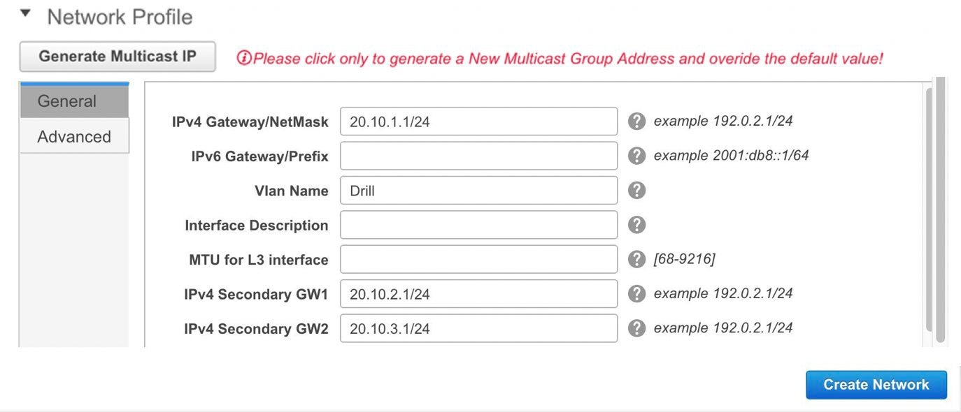
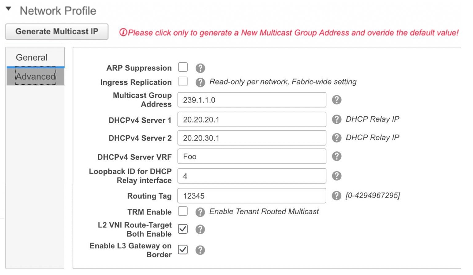
Click Create Network. A message appears at the bottom right part of the screen indicating that the network is created.
The new network appears on the Networks page that comes up.

The Status is NA since the network is created but not yet deployed on the switches. Now that the network is created, you can create more networks if needed and deploy the networks on the devices in the fabric.
Export and Import Network Information
You can export network information to a .CSV file. The exported file contains information pertaining to each network, including the fabric it belongs to, the associated VRF, the network templates used to create the network, and all other configuration details that you saved during network creation.
In the Networks screen, click the Export icon to export network information as a .CSV file.
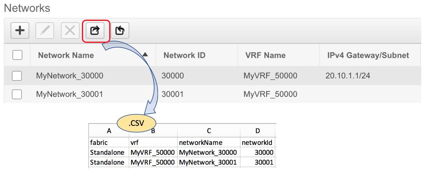
You can use the exported .CSV file for reference or use it as a template for creating new networks. To import networks, do the following:
Update new records in the .CSV file. Ensure that the networkTemplateConfig field contains the JSON Object. A message at the bottom right part of the screen displays errors and success messages. This screenshot depicts two new networks being imported.

In the Networks screen, click the Import icon and import the .CSV file into DCNM.
You can see that the imported networks are displayed in the Networks screen.

| Step 1 |
Click Control > Networks. |
||
| Step 2 |
Choose a fabric from the SCOPE drop-down list. |
||
| Step 3 |
Choose a network. |
||
| Step 4 |
Click the Edit icon. |
||
| Step 5 |
Update the fields in the General and Advanced tabs of the Network Profile area as needed.
|
||
| Step 6 |
Click Save at the bottom right part of the window to save the updates. |
Click Control > VRFs (under Fabrics submenu).
The VRFs screen comes up.
Choose the correct fabric from SCOPE. When you select a fabric, the VRFs screen refreshes and lists VRFs of the selected fabric.

Click the + button to add VRFs to the Standalone fabric. The Create VRF screen comes up. Most of the fields are autopopulated.
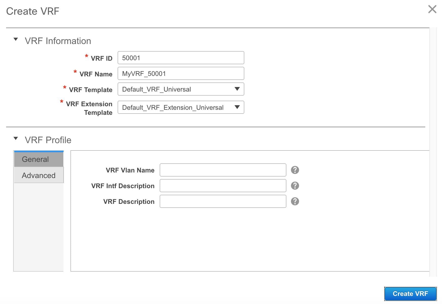
The fields in this screen are:
VRF ID and VRF Name: The ID and name of the VRF.
 Note |
For ease of use, the VRF creation option is also available while you create a network. |
VRF Template: This template is applicable for VRF creation, and only applicable for leaf switches.
VRF Extension Template: The template is applicable when you extend the VRF to other fabrics, and is applicable for border devices.
Fill the fields in the VRF Profile section.
General tab – Enter the VLAN ID of the VLAN associated with the VRF, the corresponding Layer 3 virtual interface, and the VRF ID.
Advanced tab – The fields in the tab are autopopulated.
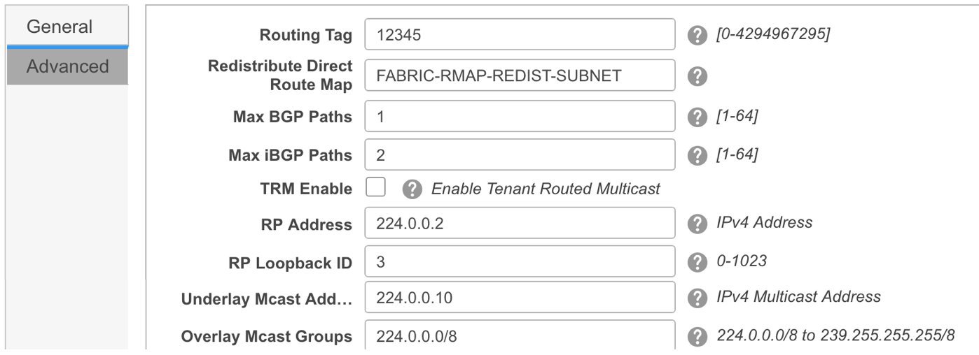
Routing Tag – If a VLAN is associated with multiple subnets, then this tag is associated with the IP prefix of each subnet. Note that this routing tag is associated with overlay network creation too.
Redistribute Direct Route Map – Specifies the route map name for redistribution of routes in the VRF.
Max BGP Paths and Max iBGP Paths – Specifies the maximum BGP and iBGP paths.
TRM Enable – Select the check box to enable TRM.
If you enable TRM, then the RP address, and the underlay multicast address must be entered.
Is RP External – Enable this checkbox if the RP is external to the fabric. If this field is unchecked, RP is distributed in every VTEP.
RP Address – Specifies the IP address of the RP.
RP Loopback ID – Specifies the loopback ID of the RP, if Is RP External is not enabled.
Underlay Multicast Address – Specifies the multicast address associated with the VRF. The multicast address is used for transporting multicast traffic in the fabric underlay. Note |
The multicast address in the Default MDT Address for TRM VRFs field in the fabric settings screen is auto-populated in this field. You can override this field if a different multicast group address should be used for this VRF. |
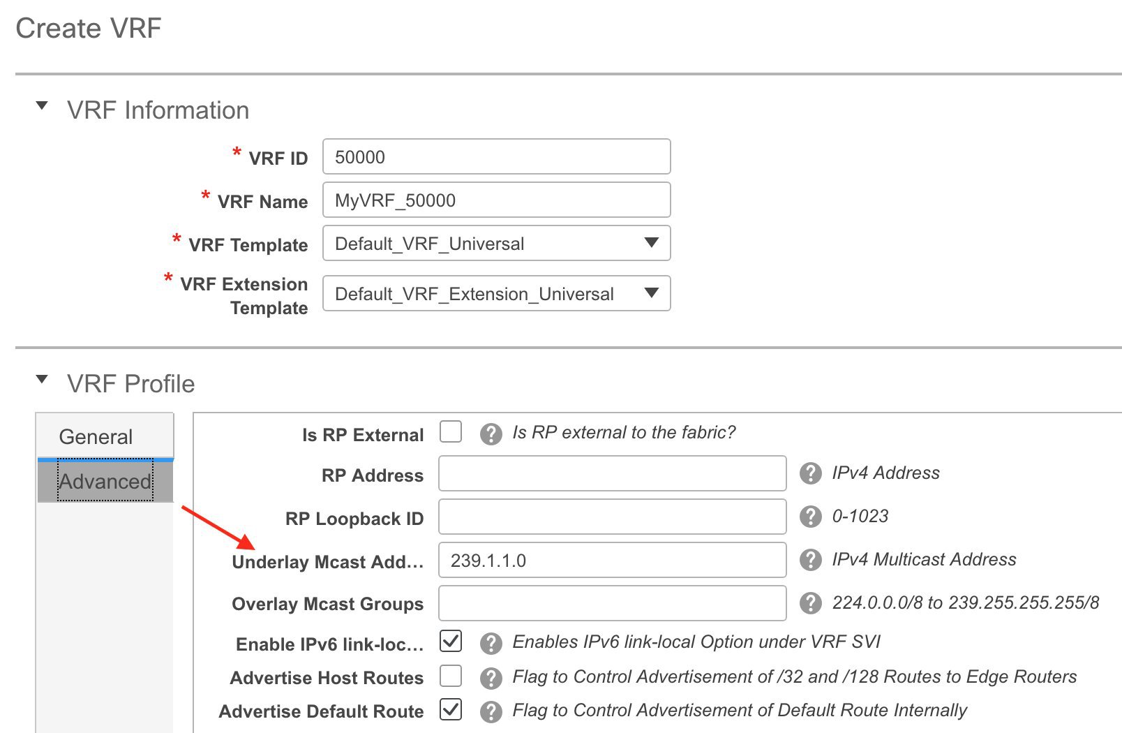
Overlay Multicast Groups – Specifies the multicast group subnet for the specified RP. The value is the group range in “ip pim rp-address” command. If the field is empty, 224.0.0.0/24 is used as default.
Enable IPv6 link-local Option - Select the check box to enable the IPv6 link-local option under the VRF SVI. If this check box is unchecked, IPv6 forward is enabled.
Advertise Host Routes – Enable the checkbox to control advertisement of /32 and /128 routes to Edge Routers.
Advertise Default Route – Enable the checkbox to control advertisement of default routes internally.
To allow inter-subnet communication between end hosts in different VXLAN fabrics, where the subnets are present in both fabrics, you must disable the Advertise Default Route feature (clear the Advertise Default Route checkbox) for the associated VRF. This will result in /32 routes for hosts being seen in both fabrics. For example, Host1 (VNI 30000, VRF 50001) in Fabric1 can send traffic to Host2 (VNI 30001, VRF 50001) in Fabric2 only if the host route is present in both fabrics. When a subnet is present in only one fabric then default route is sufficient for inter-subnet communication.
Sample screenshots of the Create VRF screen:
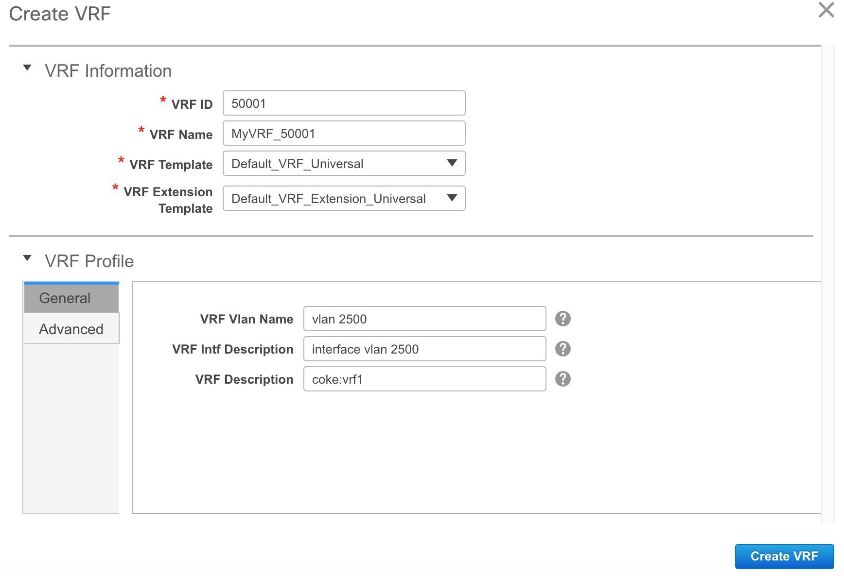
Advanced tab:
Click Create VRF.
The MyVRF_50001 VRF is created and appears on the VRFs page.

Export and Import VRF Information
You can export VRF information to a .CSV file. The exported file contains information pertaining to each VRF, including the fabric it belongs to, the templates used to create the VRF, and all other configuration details that you saved during VRF creation.
In the VRFs screen, click the Export icon to export VRF information as a .CSV file.
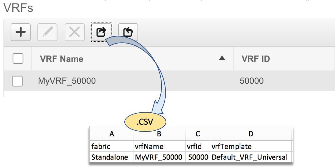
You can use the exported .CSV file for reference or use it as a template for creating new VRFs. To import VRFs, do the following:
Update new records in the .CSV file. Ensure that the vrfTemplateConfig field contains the JSON Object.
In the VRFs screen, click Import icon and import the .CSV file into DCNM.
A message at the bottom right part of the screen displays errors and success messages. This screenshot depicts a new VRF being imported.
 Note |
When you create a VRF using the Import option on the VRF window or using the DCNM APIs, you might see an error saying: Instance name is not specified. This error is because of a tagging issue. To remove this error, edit the VRF in DCNM Web UI and then deploy. |

You can see that the imported VRF is displayed in the VRFs screen.

Choose the correct fabric from SCOPE. When you select a fabric, the VRFs screen refreshes and lists VRFs of the selected fabric.

From the Select a Fabric drop-down list, select the fabric Standalone, and click Continue on the top right part of the screen. The Networks page is displayed.
Click the VRF View at the top right part of the screen. The VRFs page appears.

Select the VRF and click the Edit option at the top left part of the screen. The Edit VRF screen comes up.
Update the fields in the General and Advanced tabs of the VRF Profile section as needed.
Click Save at the bottom right part of the screen to save the updates.
You can undeploy VRFs and networks from the deployment screen. The DCNM screen flow for undeployment is similar to the deployment process flow. Go to the deployment screen (Topology View) to undeploy networks:
Click Control > Networks (under Fabrics submenu).
The Networks screen comes up.
Choose the correct fabric from SCOPE. When you select a fabric, the Networks screen refreshes and lists networks of the selected fabric.

Select the networks that you want to undeploy and click Continue. The topology view comes up.
Select the Multi-Select button (if you are undeploying the networks from multiple switches), and drag the cursor across switches with the same role. The Network Attachment screen comes up.
(For a single switch, double-click the switch and the Network Attachment screen comes up).
(For a single switch, double-click the switch and the Switches Deploy screen comes up).
In the Network Attachment screen, the Status column for the deployed networks is displayed as DEPLOYED. Clear the check boxes next to the switches, as needed. Ensure that you repeat this on all tabs since each tab represents a network.
Click Save (at the bottom right part of the screen) to initiate the undeployment of the networks. The Topology View comes up again.
 Note |
Alternatively, you can click the Detailed View button to undeploy networks. |
Refresh the screen, preview configurations if needed and click Deploy to remove the network configurations on the switches. After the switch icons turn green, it indicates successful undeployment.
Go to the Networks page to verify if the networks are undeployed.
You can undeploy VRFs from the deployment screen. The DCNM screen flow for undeployment is similar to the deployment process flow.
Choose Control > Fabrics > VRFs.
Choose the correct fabric from SCOPE. When you select a fabric, the VRFs screen refreshes and lists networks of the selected fabric.
Select the VRFs that you want to undeploy and click Continue. The Topology View page comes up.
Select the Multi-Select option (if you are undeploying the VRFs from multiple switches), and drag the cursor across switches with the same role. The VRF Attachment screen comes up.
(For a single switch, double-click the switch and the VRF Attachment screen comes up).
In the Switches Deploy screen, the Status column for the deployed VRFs is displayed as DEPLOYED. Clear the check boxes next to the switches, as needed. Ensure that you repeat this on all tabs since each tab represents a VRF.
Click Save (at the bottom right part of the screen) to initiate the undeployment of the VRFs. The topology view comes up again.
 Note |
Alternatively, you can click the Detailed View button to undeploy VRFs. |
Refresh the screen, preview configurations if needed and click Deploy to remove the VRF configurations on the switches. After the switch icons turn green, it indicates successful undeployment.
Go to the VRFs page to verify if the networks are undeployed.
If you want to delete networks and corresponding VRFs in the MSD fabric, follow this order:
Undeploy the networks, if not already done.
Delete the networks.
Undeploy the VRFs, if not already done.
Delete the VRFs.
The following procedure shows how to tag multiple VLAN IDs to a single VNI in DCNM.
| Step 1 |
Navigate to Control > Networks. |
| Step 2 |
Select the fabric from the Scope drop-down list and then select the network. Click Continue. |
| Step 3 |
Check the Multi-Select check box and drag the cursor over the switches that needs to be updated with VLAN IDs. 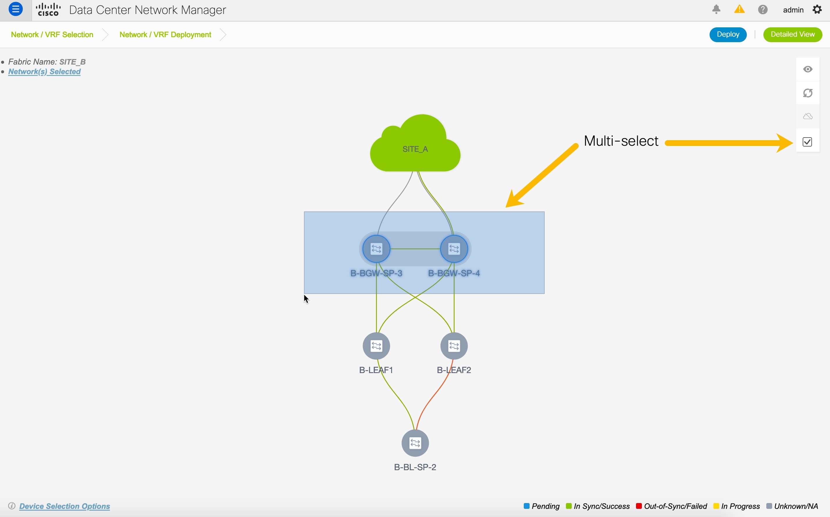 |
| Step 4 |
In the Network Attachment window, edit the VLAN ID for the switches and click Save. 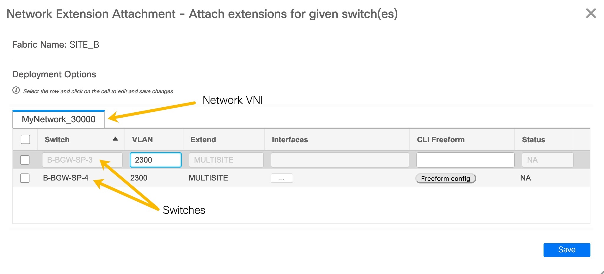 |
| Step 5 |
Click Deploy to deploy the configuration. |