DCNM Server
The DCNM Server menu includes the following submenus:
Starting, Restarting, and Stopping Services
By default, the ICMP connectivity between DCNM and its switches validates the connectivity during Performance Management. If you disable ICMP, Performance Management data will not be fetched from the switches. You can configure this parameter in the server properties. To disable ICMP connectivity check from Cisco DCNM Web UI, choose Administration > DCNM Server > Server Properties, and set skip.checkPingAndManageable parameter value to true.
To clean up the performance manager database (PM DB) stale entries, start, restart, or stop a service, from the Cisco DCNM Web UI, perform the following steps:
 Note |
During restart, the Performance Manager waits for 20minutes for the Elasticsearch to become operational. After 20minutes, the Performance Manager aborts. Click the Re-init Elasticsearch DB Schema icon in the Actions column for the Performance collector service. |
Procedure
| Step 1 |
Choose Administration > DCNM Server > Server Status. The Status window appears that displays the server details. |
| Step 2 |
In the Actions column, click the action you want to perform. You can perform the following actions:
|
| Step 3 |
View the status in the Status column. |
What to do next
See the latest status in the Status column.
Using the Commands Table
The commands table contains links to commands that launch new dialog boxes to provide information about the server status and server administrative utility scripts. You can execute these commands directly on the server CLI.
-
ifconfig: click this link to view information about interface parameters, IP address, and netmask used on the Cisco DCNM server.
-
appmgr status all: click this link to view the DCNM server administrative utility script that checks the status of different services currently running.
-
appmgr show vmware-info: click this link to view information about the CPU and Memory of Virtual Machine.
-
clock: click this link to view information about the server clock details such as time, zone information.
Note |
The commands section is applicable only for the OVA or ISO installations. |
Customization
From Cisco DCNM Release 11.3(1), you can modify the background image and message on the Web UI login page. This feature helps you to distinguish between the DCNM instances, when you have many instances running at the same time. You can also use a company-branded background on the login page. Click on Restore Defaults to reset the customizations to their original default values.
To remove the customizations and restore to the default values, click Restore defaults.
Login Image
This feature allows you to change the background image on the Cisco DCNM Web UI login page. If you have many instances of DCNM, this will help you identify the correct DCNM instance based on the background image.
To edit the default background image for your Cisco DCNM Web UI login page, perform the following steps:
-
Choose Administration > DCNM Server > Customization.
-
In the Login Image area, click Add (+) icon.
Browse for the image that you need to upload from your local directory. You can choose any of the following format images: JPG, GIF, PNG, and SVG.
-
Select the image and click Open.
A status message appears on the right-bottom corner.
Login image
Upload Successful
Note
We recommend that you upload a scaled image for fast load times.
The uploaded image is selected and applied as the background image.
-
To choose an existing image as login image, select the image and wait until you see the message on the right-bottom corner.
-
To revert to the default login image, click Restore Defaults.
Message of the day (MOTD)
This feature allows you to add a message to the Cisco DCNM Web UI login page. You can a list of messages that will rotate on the configured frequency. This feature allows you to convey important messages to the user on the login page.
To add or edit the message of the day on the Cisco DCNM Web UI login page, perform the following steps:
-
Choose Administration > DCNM Server > Customization.
-
In the Message of the day (MOTD) field, enter the message that must appear on the login page.
-
Click Save.
Viewing Log Information
You can view the logs for performance manager, SME server, web reports, web server, and web services. These processes have no corresponding GUI that allows you to view information about these log files. If you see errors, preserve these files for viewing.
Beginning with Release 11.2(1), for DCNM OVA and DCNM ISO installations, all log files with .log extension are also listed.
Note |
Logs cannot be viewed from a remote server in a federation. |
To view the logs from the Cisco DCNM Web UI, perform the following steps:
Procedure
| Step 1 |
Choose Administration > DCNM Server > Logs. You see a tree-based list of logs in the left column. Under the tree, there is a node for every server in the federation. The log files are under the corresponding server node. |
||
| Step 2 |
Click a log file under each node of the tree to view it on the right. |
||
| Step 3 |
Double-click the tree node for each server to download a ZIP file containing log files from that server. |
||
| Step 4 |
(Optional) Click Generate Techsupport to generate and download files required for technical support. This file contains more information in addition to log files.
|
||
| Step 5 |
(Optional) Click the Print icon on the upper right corner to print the logs. |
Server Properties
You can set the parameters that are populated as default values in the DCNM server.
To set the parameters of the DCNM server from the Cisco DCNM Web UI, perform the following steps:
Procedure
| Step 1 |
Choose Administration > DCNM Server > Server Properties. |
| Step 2 |
Click Apply Changes to save the server settings. |
Configuring SFTP/TFTP/SCP Credentials
A file server is required to collect device configuration and restoring configurations to the device.
To configure the SFTP/TFTP/SCP credentials for a file store from the Cisco DCNM Web UI, perform the following steps:
Procedure
| Step 1 |
Choose Administration > DCNM Server > Archive FTP Credentials. The Archive FTP Credentials window is displayed.
|
||
| Step 2 |
In the Server Type field, use the radio button to select SFTP.
|
||
| Step 3 |
In the Server Type field, use the radio button to select TFTP. Cisco DCNM uses a local TFTP server for data transfer. Ensure that there is no external TFTP server running on the DCNM server.
|
||
| Step 4 |
In the Server Type field, use the radio button to select SCP.
|
||
| Step 5 |
Choose Configuration > Templates > Templates Library > Jobs to view individual device verification status. The configurations that are backed up are removed from the file server and are stored in the file system. |
SFTP Directory Path
Use Case 1:
If Cisco DCNM is installed on Linux platforms, like OVA, ISO, or Linux, and the test folder is located at /test/sftp/, you must provide the entire path of the SFTP directory. In the SFTP Directory field, enter /test/sftp.
Use Case 2:
If Cisco DCNM is installed on the Windows platform, and the test folder is located at C://Users/test/sftp/, you must provide the relative path of the SFTP directory. In the SFTP Directory field, enter /.
For Example:
-
If the path in the external SFTP is C://Users/test/sftp/, then the Cisco DCNM SFTP Directory path must be /.
-
If the path in the external SFTP is C://Users/test, then the Cisco DCNM SFTP Directory path must be /sftp/.
Examples for SCP Directory Path
Use Case 1:
If Cisco DCNM is installed on Linux platforms, like OVA, ISO, or Linux, and the test folder is located at /test/scp/, you must provide the entire path of the SCP directory. In the SCP Directory field, enter /test/scp.
Use Case 2:
If Cisco DCNM is installed on the Windows platform, and the test folder is located at C://Users/test/scp/, you must provide the relative path of the SCP directory. In the SCP Directory field, enter /.
For Example:
-
If the path in the external SCP is C://Users/test/scp/, then the Cisco DCNM SCP directory path must be /.
-
If the path in the external SCP is C://Users/test, then the Cisco DCNM SCP directory path must be /scp/.
Modular Device Support
To support any new hardware that does not require many major changes, a patch can be delivered instead of waiting for the next DCNM release. Modular Device Support helps to deliver and apply the DCNM patch releases. An authorized DCNM administrator can apply the patch to the production setup. Patch releases are applicable for the following scenarios:
-
Support any new hardware, like chassis or line cards
-
Support latest NX-OS versions
-
Support critical fixes as patches
To view the patch details from Cisco DCNM Web UI, perform the following steps:
Procedure
| Step 1 |
Choose Administration > DCNM Server > Modular Device Support. You see the DCNM Servers column on the left in the window and Modular Device support information window on the right. |
| Step 2 |
Expand DCNM Servers to view all the DCNM servers. It includes the list of patches installed along with the version number, corresponding platforms supported, chassis supported, NX-OS version supported, PID supported, backup directory and the last patch deployment time in the Modular Device support information table. |
What to do next
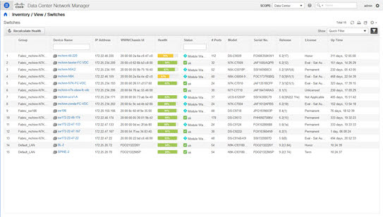
Managing Switch Groups
You can configure switch groups by using Cisco DCNM Web UI. You can add, delete, or move a switch to a group, or move switches from a group to another group.
Creating switch groups will help you to manage switches because they are grouped logically. For example, you can create host or flow policies for switches in a specific switch group instead of creating it for all the switches. Similarly, you can view the flow topology for a specific switch group containing switches.
The switch groups are listed under the SCOPE drop-down list at the top right part of windows under Media Controller.
Note |
The hostname of the switch should be unique across all the switch groups. You cannot have the same hostname and management IP address for two different switches in two switch groups. |
This section contains the following:
Adding Switch Groups
To add switch groups from the Cisco DCNM Web UI, perform the following steps:
Procedure
| Step 1 |
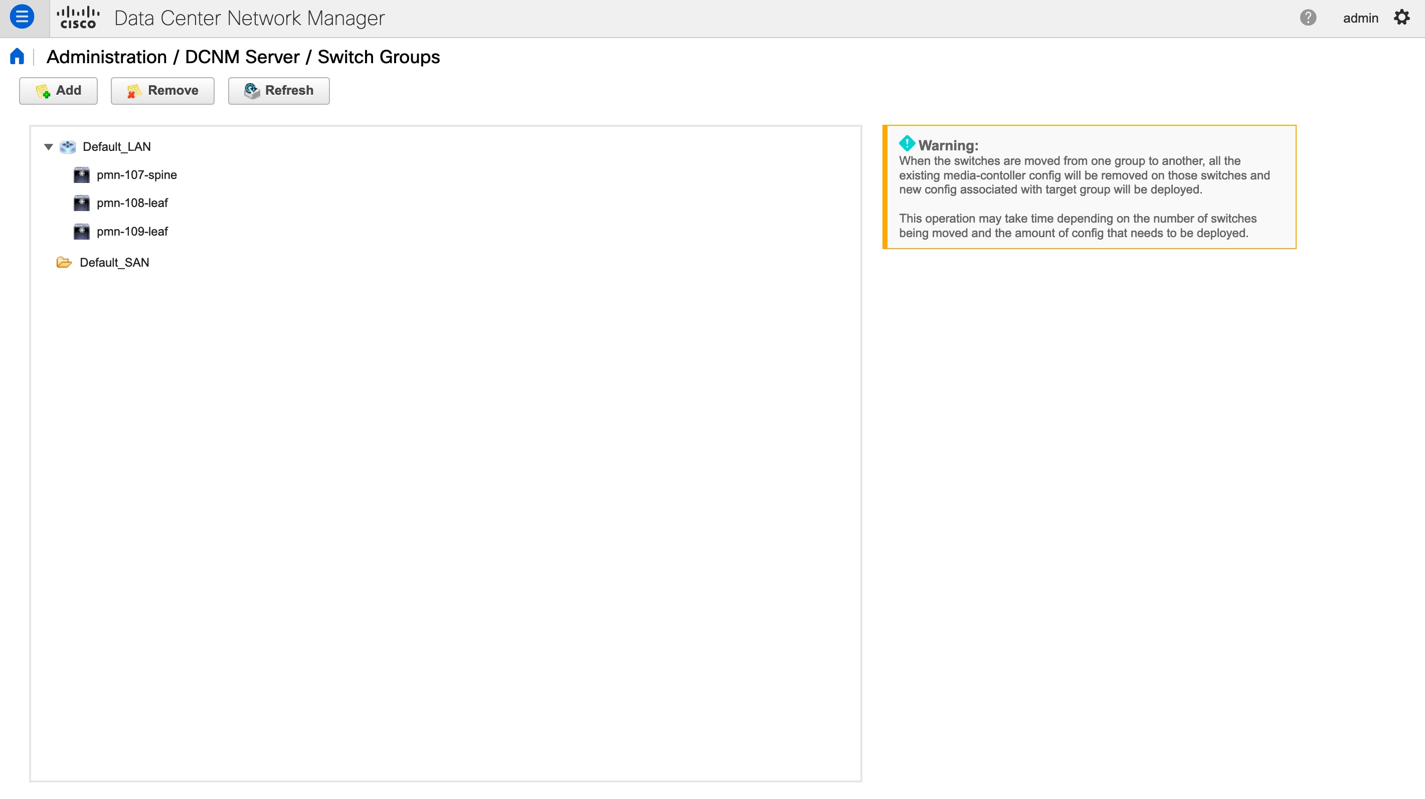
Choose Administration > DCNM Server > Switch Groups.
|
||
| Step 2 |
Click the Add icon. The Add Group window is displayed, that allows you to enter the name for the switch group. |
||
| Step 3 |
Enter the name of the switch group and click Add to complete adding the switch group. The switch group name validation, and the maximum tree depth is 10. If you do not choose a parent group before adding a new switch group, the new group is added on the top of the hierarchy. Whenever you add a new switch group, the default policies are automatically created for this switch group.
|
Removing a Group or a Member of a Group
You can remove a group or a member of the group from the Cisco DCNM Web UI. When you remove a group, the ethernet switches of the deleted group are moved to the default LAN group. When you remove a member of a group, the member is moved to the default LAN group.
To remove a group or a member of a group from the Cisco DCNM Web UI, perform the following steps:
Procedure
| Step 1 |
Choose the switch group or members of a group that you want to remove. |
||
| Step 2 |
Click the Remove icon. A dialog box prompts you to confirm the deletion of the switch group or the member of the group.
|
||
| Step 3 |
Click Yes to delete or No to cancel the action.
|
Moving a Switch to Another Group
To move a switch to another group from the Cisco DCNM Web UI, perform the following steps:
 Warning |
When the switches are moved from one group to another, all the existing media-controller config will be removed on those switches and new config associated with target group will be deployed. This operation may take time depending on the number of switches being moved and the amount of config that needs to be deployed. |
Procedure
| Step 1 |
Select a switch. |
| Step 2 |
Drag the highlighted switch to another group. To move multiple switches across different switch groups, use Ctrl key or Shift key. |
Native HA
Before you begin
Note |
Ensure that you clear your browser cache and cookies everytime after a Federation switchover or failover. |
Procedure
| Step 1 |
By default, DCNM is bundled with an embedded database engine PostgreSQL. The native DCNM HA is achieved by two DCNMs running as Active / Warm Standby, with their embedded databases synchronized in real time. So once the active DCNM is down, the standby takes over with the same database data and resume the operation. The standby host database down scenario is documented after this procedure. |
| Step 2 |
From the menu bar, choose Administration > DCNM Server > Native HA. You see the Native HA window. |
| Step 3 |
You can allow manual failover of DCNM to the standby host by clicking the Failover button, and then click OK.
|
| Step 4 |
You can allow manual syncing database and disk files to standby host by clicking Force Sync, and then click OK. |
| Step 5 |
You can test or validate the HA setup by clicking Test and then click OK. |
What to do next
Some HA troubleshooting scenarios are noted in this sub section.
The standby host database is down: Typically, the DCNM database (PostgreSQL) is up on the active and standby hosts. In DCNM 10.1 and earlier versions, the standby database can be down due to a database synchronization failure.
-
Enter “ps -ef | grep post”. You should see multiple postgres processes running. If not, it indicates that the database is down.
-
Restore database data from a backup file that is created at the beginning of database synchronization. Change directory to “/usr/local/cisco/dcm/db”
-
Check existence of file replication/ pgsql-standby-backup.tgz. If the file exists, restore database data files:
rm -rf    data/*
tar -zxf    replication/ pgsql-standby-backup.tgz    data
/etc/init.d/postgresql-9.4 start
ps -ef | grep post
The active DCNM host will synchronize the two databases.
The TFTP server is not bound to the eth1 VIP address on the active host: The TFTP server should run on the active host (not on the standby host), and it should be bound to the eth1 VIP address. In some setups, the bind address is not the VIP address, as per the TFTP configuration file, and this could cause issues when switches try to use TFTP.
-
Enter “grep bind /etc/xinetd.d/tftp” to check if the TFTP configuration file has the right bind address. If the displayed IP address is not the eth1 VIP address, then change the bind address to the VIP address. Repeat the procedure for the standby host. Update the bind address to the VIP address.
-
Enter " " /etc/init.d/xinetd restart” on the active host to restart TFTP.
Note |
The TFTP server can be started or stopped with the “appmgr start/stop ha-apps” command. |
Multi Site Manager
Procedure
| Step 1 |
Multi-Site-Manager (MsM) provides a single pane for users to search for switches that are managed by DCNM globally. MSM can do realtime search to find out which switch globally handles the traffic for a given virtual machine based on IP address, name or mac address, and supporting VXLAN basing on segment ID as well. It provides hyperlink to launch the switch only. This window also plays the role of remote site registration. The registration only allows the current DCNM server to access the remote DCNM server or site. For the remote site to access the current DCNM server, registration is required on the remote site as well. |
| Step 2 |
Choose Administration > DCNM Server > Multi Site Manager. The MsM window displays the overall health or status of the remote site and the application health. |
| Step 3 |
You can search by Switch, VM IP, VM Name, MAC, and Segment ID. |
| Step 4 |
You can add a new DCNM server by clicking +Add DCNM Server. The Enter Remote DCNM Server Information window opens. Fill in the information that is required and click OK to save. |
| Step 5 |
Click Refresh All Sites to display the updated information. |


 Feedback