Configuring Layer 3 Interfaces

About Layer 3 Interfaces

Layer 3 interfaces forward IPv4 and IPv6 packets to another device using static or dynamic routing protocols. You can use Layer 3 interfaces for IP routing and inter-VLAN routing of Layer 2 traffic.

Routed Interfaces

You can configure a port as a Layer 2 interface or a Layer 3 interface. A routed interface is a physical port that can route IP traffic to another device. A routed interface is a Layer 3 interface only and does not support Layer 2 protocols, such as the Spanning Tree Protocol (STP).

All Ethernet ports are routed interfaces by default. You can change this default behavior with the CLI setup script.


Note


The default behavior varies based on the type of switch (Cisco Nexus 9300, Cisco Nexus 9500, or Cisco Nexus 3164).


Note


Cisco Nexus 9300 Series switches (except Cisco Nexus 9332 switch) have a Layer 2 default mode.


You can assign an IP address to the port, enable routing, and assign routing protocol characteristics to this routed interface.

You can also create a Layer 3 port channel from routed interfaces. For more information about port channels, see the “Configuring Port Channels” section.

Routed interfaces support exponentially decayed rate counters. Cisco NX-OS tracks the following statistics with these averaging counters:

  • Input packets/sec

  • Output packets/sec

  • Input bytes/sec

  • Output bytes/sec

Subinterfaces

You can create virtual subinterfaces on a parent interface configured as a Layer 3 interface. A parent interface can be a physical port.

Subinterfaces divide the parent interface into two or more virtual interfaces on which you can assign unique Layer 3 parameters such as IP addresses and dynamic routing protocols. The IP address for each subinterface should be in a different subnet from any other subinterface on the parent interface.

You create a subinterface with a name that consists of the parent interface name (for example, Ethernet 2/1) followed by a period and then by a number that is unique for that subinterface. For example, you could create a subinterface for Ethernet interface 2/1 named Ethernet 2/1.1 where .1 indicates the subinterface.

Cisco NX-OS enables subinterfaces when the parent interface is enabled. You can shut down a subinterface independent of shutting down the parent interface. If you shut down the parent interface, Cisco NX-OS shuts down all associated subinterfaces as well.

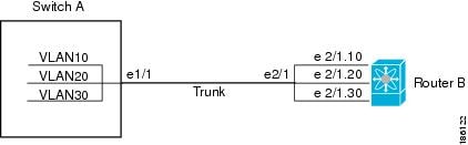
One use of subinterfaces is to provide unique Layer 3 interfaces to each virtual local area network (VLAN) supported by the parent interface. In this scenario, the parent interface connects to a Layer 2 trunking port on another device. You configure a subinterface and associate the subinterface to a VLAN ID using 802.1Q trunking.

The following figure shows a trunking port from a switch that connects to router B on interface E 2/1. This interface contains three subinterfaces that are associated with each of the three VLANs carried by the trunking port.

Figure 1. Subinterfaces for VLANs


For more information about VLANs, see the Cisco Nexus 9000 Series NX-OS Layer 2 Switching Configuration Guide.

VLAN Interfaces

A VLAN interface, or switch virtual interface (SVI), is a virtual routed interface that connects a VLAN on the device to the Layer 3 router engine on the same device. Only one VLAN interface can be associated with a VLAN.

However, you need to configure a VLAN interface for a VLAN only when you want to route between VLANs or to provide IP host connectivity to the device through a virtual routing and forwarding (VRF) instance that is not the management VRF. When you enable VLAN interface creation, Cisco NX-OS creates a VLAN interface for the default VLAN (VLAN 1) to permit remote switch administration.

Enable the VLAN network interface feature using the feature interface-vlan configuration. The system automatically takes a checkpoint prior to disabling the feature, and you can roll back to this checkpoint. See the Cisco Nexus 9000 Series NX-OS System Management Configuration Guide for information on rollbacks and checkpoints.


Note


The feature interface-vlan configuration is not available on the Nexus 9800 switches.


Layer 3 inter-VLAN Routing

You can route traffic across VLAN interfaces to provide Layer 3 inter-VLAN routing by configuring a VLAN interface for each VLAN, and assigning an IP address on the VLAN interface.

For more information about IP addresses and IP routing, see the Cisco Nexus 9000 Series NX-OS Unicast Routing Configuration Guide.

Connecting Two VLAN Interfaces

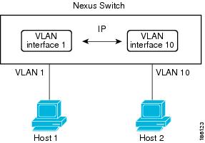
You can configure VLAN interfaces for each VLAN that allows Host 1 to communicate with Host 2 using IP routing between the VLANs. VLAN 1 communicates at Layer 3 over VLAN interface 1 and VLAN 10 communicates at Layer 3 over VLAN interface 10.

The following figure shows two hosts connected to two VLANs on a device.

Figure 2. Connecting Two VLANs with VLAN interfaces


Note


You cannot delete the VLAN interface for VLAN 1.


Loopback Interfaces

A loopback interface is a virtual interface with a single endpoint that is always up. Any packet transmitted over a loopback interface is immediately received by this interface. Loopback interfaces emulate a physical interface. You can configure up to 1024 loopback interfaces, numbered 0 to 1023.

You can use loopback interfaces for performance analysis, testing, and local communications. Loopback interfaces can act as a termination address for routing protocol sessions. This loopback configuration allows routing protocol sessions to stay up even if some of the outbound interfaces are down.

Virtualization Support

Layer 3 interfaces support Virtual Routing and Forwarding instances (VRFs). VRFs exist within virtual device contexts (VDCs). By default, Cisco NX-OS places you in the default VDC and default VRF .


Note


You must assign an interface to a VRF before you configure the IP address for that interface.


Layer 3 Static MAC Addresses

You can configure a static MAC address for the following Layer 3 interfaces:

  • Layer 3 interfaces

  • Layer 3 subinterfaces

  • Layer 3 port channels

  • VLAN network interface


Note


You cannot configure static MAC address on tunnel interfaces.


Guidelines and Limitations for Layer 3 Interfaces

Layer 3 interfaces have the following configuration guidelines and limitations:

  • show commands with the internal keyword are not supported.

  • Configuring a subinterface on a physical interface that is configured to be a member of a port-channel is not supported. One must configure the subinterface under the port-channel interface itself.

  • The Dynamic Host Configuration Protocol (DHCP) option is not supported when configuring a subinterface on a port-channel interface.

  • IPv6 counters for SVI and subinterfaces on Cisco Nexus 9500 Series Switches with X9700-EX and X9700-FX line cards are not supported.

  • Multicast and/or broadcast counters for both SVI and subinterfaces are not supported.

  • Control plane SVI/SI traffic for both SVI and subinterfaces counters are not supported.

  • Beginning Cisco NX-OS Release 9.3(6), sub-interface multicast and broadcast counters are supported on Cisco Nexus N9K-C9336C-FX2 and N9K-C93240YC-FX2 switches.

  • The SVI, Layer 2 VLAN, MPLS counters may not work when you enable subinterface multicast and broadcast counters.

  • Up to 1000 subinterfaces are supported for this statistics.


Note


If you are familiar with the Cisco IOS CLI, be aware that the Cisco NX-OS commands for this feature might differ from the Cisco IOS commands that you would use.


Default Settings

The following table lists the default settings for Layer 3 interface parameters.

Table 1. Default Layer 3 Interface Parameters

Parameters

Default

Admin state

Shut

Configuring Layer 3 Interfaces

Configuring a Routed Interface

You can configure any Ethernet port as a routed interface.

SUMMARY STEPS

  1. configure terminal
  2. interface ethernet slot/port
  3. no switchport
  4. [ip address ip-address/length | ipv6 address ipv6-address/length]
  5. show interfaces
  6. no shutdown
  7. copy running-config startup-config

DETAILED STEPS

  Command or Action Purpose

Step 1

configure terminal

Example:

switch# configure terminal
switch(config)#

Enters global configuration mode.

Step 2

interface ethernet slot/port

Example:

switch(config)# interface ethernet 2/1
switch(config-if)#

Enters interface configuration mode.

Step 3

no switchport

Example:

switch(config-if)# no switchport

Configures the interface as a Layer 3 interface.

Step 4

[ip address ip-address/length | ipv6 address ipv6-address/length]

Example:

switch(config-if)# ip address 192.0.2.1/8

Example:

switch(config-if)# ipv6 address 2001:0DB8::1/8

Step 5

show interfaces

Example:

switch(config-if)# show interfaces ethernet 2/1

(Optional) Displays the Layer 3 interface statistics.

Step 6

no shutdown

Example:

switch# 
switch(config-if)# int e2/1
switch(config-if)# no shutdown

(Optional) Clears the errors on the interfaces where policies correspond with hardware policies. This command allows policy programming to continue and the port to come up. If policies do not correspond, the errors are placed in an error-disabled policy state.

Step 7

copy running-config startup-config

Example:

switch(config)# copy running-config startup-config  

(Optional) Saves the configuration change.

Example

  • Use the medium command to set the interface medium to either point to point or broadcast.

Command

Purpose

medium {broadcast | p2p}

Example:

switch(config-if)# medium p2p

Configures the interface medium as either point to point or broadcast.


Note


The default setting is broadcast , and this setting does not appear in any of the show commands. However, if you do change the setting to p2p , you will see this setting when you enter the show running config command.


  • Use the switchport command to convert a Layer 3 interface into a Layer 2 interface.

Command

Purpose

switchport

Example:

switch(config-if)# switchport

Configures the interface as a Layer 2 interface and deletes any configuration specific to Layer 3 on this interface.

  • This example shows how to configure a routed interface:

    switch# configure terminal
    switch(config)# interface ethernet 2/1
    switch(config-if)# no switchport
    switch(config-if)# ip address 192.0.2.1/8 
    switch(config-if)# copy running-config startup-config

    The default setting for interfaces is routed. If you want to configure an interface for Layer 2, enter the switchport command. Then, if you change a Layer 2 interface to a routed interface, enter the no switchport command.

Configuring a Subinterface on a Routed Interface

You can configure one or more subinterfaces on a routed interface made from routed interfaces.

Before you begin

Configure the parent interface as a routed interface.

See the “Configuring a Routed Interface” section.

SUMMARY STEPS

  1. configure terminal
  2. interface ethernet slot/port.number
  3. [ip address ip-address/length | ipv6 address ipv6-address/length]
  4. encapsulation dot1Q vlan-id
  5. show interfaces
  6. copy running-config startup-config

DETAILED STEPS

  Command or Action Purpose

Step 1

configure terminal

Example:

switch# configure terminal
switch(config)#

Enters global configuration mode.

Step 2

interface ethernet slot/port.number

Example:

switch(config)# interface ethernet 2/1.1
switch(config-subif)#

Creates a subinterface and enters subinterface configuration mode. The number range is from 1 to 4094.

Step 3

[ip address ip-address/length | ipv6 address ipv6-address/length]

Example:

switch(config-subif)# ip address 192.0.2.1/8

Example:

switch(config-subif)# ipv6 address 2001:0DB8::1/8

Step 4

encapsulation dot1Q vlan-id

Example:

switch(config-subif)# encapsulation dot1Q 33

Configures IEEE 802.1Q VLAN encapsulation on the subinterface. The range is from 2 to 4093.

Step 5

show interfaces

Example:

switch(config-subif)# show interfaces ethernet 2/1.1

(Optional) Displays the Layer 3 interface statistics.

Step 6

copy running-config startup-config

Example:

switch(config)# copy running-config startup-config  

(Optional) Saves the configuration change.

Example

  • This example shows how to create a subinterface:

    switch# configure terminal
    switch(config)# interface ethernet 2/1.1
    switch(config-if)# ip address 192.0.2.1/8 
    switch(config-if)# encapsulation dot1Q 33
    switch(config-if)# copy running-config startup-config
    
  • The output of the show interface eth command is enhanced for the subinterfaces as shown in the following :

    switch# show interface ethernet 1/2.1 
    Ethernet1/2.1 is down (Parent Interface Admin down)
    admin state is down, Dedicated Interface, [parent interface is Ethernet1/2]
    Hardware: 40000 Ethernet, address: 0023.ac67.9bc1 (bia 4055.3926.61d4)
    Internet Address is 10.10.10.1/24
    MTU 1500 bytes, BW 40000000 Kbit, DLY 10 usec
    reliability 255/255, txload 1/255, rxload 1/255
    Auto-mdix is turned off
    EtherType is 0x8100 
    L3 in Switched:
    	ucast: 0 pkts, 0 bytes - mcast: 0 pkts, 0 bytes
    L3 out Switched:
        ucast: 0 pkts, 0 bytes - mcast: 0 pkts, 0 bytes

Configuring a VLAN Interface

You can create VLAN interfaces to provide inter-VLAN routing.

SUMMARY STEPS

  1. configure terminal
  2. feature interface-vlan
  3. interface vlan number
  4. [ip address ip-address/length | ipv6 address ipv6-address/length]
  5. show interface vlan number
  6. no shutdown
  7. copy running-config startup-config

DETAILED STEPS

  Command or Action Purpose

Step 1

configure terminal

Example:

switch# configure terminal
switch(config)#

Enters configuration mode.

Step 2

feature interface-vlan

Example:

switch(config)# feature interface-vlan

Enables VLAN interface mode.

Step 3

interface vlan number

Example:

switch(config)# interface vlan 10
switch(config-if)#

Creates a VLAN interface. The number range is from 1 to 4094.

Step 4

[ip address ip-address/length | ipv6 address ipv6-address/length]

Example:

switch(config-if)# ip address 192.0.2.1/8

Example:

switch(config-if)# ipv6 address 2001:0DB8::1/8

Step 5

show interface vlan number

Example:

switch(config-if)# show interface vlan 10

(Optional) Displays the Layer 3 interface statistics.

Step 6

no shutdown

Example:

switch(config)# int e3/1
switch(config)# no shutdown

(Optional) Clears the errors on the interfaces where policies correspond with hardware policies. This command allows policy programming to continue and the port to come up. If policies do not correspond, the errors are placed in an error-disabled policy state.

Step 7

copy running-config startup-config

Example:

switch(config-if)# copy running-config startup-config  

(Optional) Saves the configuration change.

Example

This example shows how to create a VLAN interface:

switch# configure terminal
switch(config)# feature interface-vlan
switch(config)# interface vlan 10
switch(config-if)# ip address 192.0.2.1/8
switch(config-if)# copy running-config startup-config

Configuring a Static MAC Address on a Layer 3 Interface

You can configure static MAC addresses on Layer 3 interfaces. You cannot configure broadcast or multicast addresses as static MAC addresses.


Note


You cannot configure static MAC addresses on tunnel interfaces.


Note


This configuration is limited to 16 VLAN interfaces. Applying the configuration to additional VLAN interfaces results in a down state for the interface with a Hardware prog failed. status.


SUMMARY STEPS

  1. config t
  2. interface [ethernet slot/port | ethernet slot/port.number | port-channel number | vlan vlan-id]
  3. mac-address mac-address
  4. exit
  5. (Optional) show interface [ethernet slot/port | ethernet slot/port.number | port-channel number | vlan vlan-id]
  6. (Optional) copy running-config startup-config

DETAILED STEPS

  Command or Action Purpose

Step 1

config t

Example:

switch# config t
switch(config)#

Enters configuration mode.

Step 2

interface [ethernet slot/port | ethernet slot/port.number | port-channel number | vlan vlan-id]

Example:

switch(config)# interface ethernet 7/3

Specifies the Layer 3 interface and enters the interface configuration mode.

Note


You must create the Layer 3 interface before you can assign the static MAC address.

Step 3

mac-address mac-address

Example:

switch(config-if)# mac-address 22ab.47dd.ff89
switch(config-if)#

Specified a static MAC address to add to the Layer 3 interface.

Step 4

exit

Example:

switch(config-if)# exit
switch(config)#

Exits the interface mode.

Step 5

(Optional) show interface [ethernet slot/port | ethernet slot/port.number | port-channel number | vlan vlan-id]

Example:

switch# show interface ethernet 7/3
(Optional)

Displays information about the Layer 3 interface.

Step 6

(Optional) copy running-config startup-config

Example:

switch# copy running-config startup-config
(Optional)

Copies the running configuration to the startup configuration.

Example

This example shows how to configure the Layer 3 interface on slot 7, port 3 with a static MAC address:

switch# config t
switch(config)# interface ethernet 7/3
switch(config-if)# mac-address 22ab.47dd.ff89
switch(config-if)# 

Configuring a Loopback Interface

You can configure a loopback interface to create a virtual interface that is always up.

Before you begin

Ensure that the IP address of the loopback interface is unique across all routers on the network.

SUMMARY STEPS

  1. configure terminal
  2. interface loopback instance
  3. [ip address ip-address/length | ipv6 address ipv6-address/length]
  4. show interface loopback instance
  5. copy running-config startup-config

DETAILED STEPS

  Command or Action Purpose

Step 1

configure terminal

Example:

switch# configure terminal
switch(config)#

Enters configuration mode.

Step 2

interface loopback instance

Example:

switch(config)# interface loopback 0
switch(config-if)#

Creates a loopback interface. The range is from 0 to 1023.

Step 3

[ip address ip-address/length | ipv6 address ipv6-address/length]

Example:

switch(config-if)# ip address 192.0.2.1/8

Example:

switch(config-if)# ipv6 address 2001:0DB8::1/8

Step 4

show interface loopback instance

Example:

switch(config-if)# show interface loopback 0

(Optional) Displays the loopback interface statistics.

Step 5

copy running-config startup-config

Example:

switch(config-if)# copy running-config startup-config  

(Optional) Saves the configuration change.

Example

This example shows how to create a loopback interface:

switch# configure terminal
switch(config)# interface loopback 0
switch(config-if)# ip address 192.0.2.1/8
switch(config-if)# copy running-config startup-config

Configuring PBR on SVI on the Gateway

This procedure configures PBR on the primary SVI interface in the gateway.


Note


Steps 2 through 6 are needed if you want to configure a PBR policy on the unnumbered Primary/Secondary VLAN interfaces. This is not mandatory for IP unnumbered on the SVI feature.


SUMMARY STEPS

  1. configure terminal
  2. ip access-list list-name
  3. permit tcp host ipaddr host ipaddr eq port-number
  4. exit
  5. route-map route-map-name
  6. match ip address access-list-name
  7. set ip next-hop addr1
  8. exit
  9. interface vlan vlan-id
  10. ip address ip-addr
  11. no ip redirects
  12. (Optional) ip policy route-map pbr-sample
  13. exit
  14. hsrp version 2
  15. hsrpgroup-num
  16. name name-val
  17. ip ip-addr
  18. no shutdown

DETAILED STEPS

  Command or Action Purpose

Step 1

configure terminal

Example:

switch# configure terminal 

Enter global configuration mode.

Step 2

ip access-list list-name

Example:

switch(config)# ip access-list pbr-sample 

Configure access list.

Step 3

permit tcp host ipaddr host ipaddr eq port-number

Example:

switch(config-acl)# permit tcp host 10.1.1.1 host 192.168.2.1 eq 80

Specify the packets to forward on a specific port.

Step 4

exit

Example:

switch(config-acl)# exit

Exit configuration mode.

Step 5

route-map route-map-name

Example:

switch(config)# route-map pbr-sample

Create a route-map or enter route-map command mode.

Step 6

match ip address access-list-name

Example:

switch(config-route-map)# match ip address pbr-sample

Match values from the routing table.

Step 7

set ip next-hop addr1

Example:

switch(config-route-map)# set ip next-hop 192.168.1.1

Set IP address of the next hop.

Step 8

exit

Example:

switch(config-route-map)# exit

Exit command mode.

Step 9

interface vlan vlan-id

Example:

switch(config)# interface vlan 2003

Creates a VLAN interface and enters interface configuration mode. The range is from 1 and 4094.This is the primary VLAN.

Step 10

ip address ip-addr

Example:

switch(config-if)# ip address 10.0.0.1/8

Configures an IP address for the interface.

Step 11

no ip redirects

Example:

switch(config-if)# no ip redirects

Needs to be configured on all unnumbered primary and secondary VLAN interfaces.

Step 12

(Optional) ip policy route-map pbr-sample

Example:

switch(config-if)# ip policy route-map pbr-sample
(Optional)

Enter this command if you want to apply a PBR policy on the unnumbered Primary/Secondary VLAN interface.

Step 13

exit

Example:

switch(config-if)# exit

Exit command mode.

Step 14

hsrp version 2

Example:

switch(config-if)# hsrp version 2

Set the HSRP version.

Step 15

hsrpgroup-num

Example:

switch(config-if)# hsrp 200

Set the HSRP group number.

Step 16

name name-val

Example:

switch(config-if-hsrp)# name primary

Configure the redundancy name string.

Step 17

ip ip-addr

Example:

switch(config-if-hsrp)# ip 10.0.0.100

Configures an IP address.

Step 18

no shutdown

Example:

switch(config-if-hsrp)# no shutdown

Negates shutdown.

Configuring IP Unnumbered on SVI Secondary VLAN on the Gateway

This procedure configures IP unnumbered on the secondary SVI in the gateway. Beginning Cisco NX-OS Release 9.3(6), this feature is supported on Cisco Nexus N9K-C9316D-GX, N9K-C93600CD-GX, N9K-C9364C-GX switches.

SUMMARY STEPS

  1. configure terminal
  2. interface vlan vlan-list
  3. ip unnumbered vlan primary-vlan-id
  4. (Optional) ip policy route-map pbr-sample
  5. no ip redirects
  6. hsrp version 2
  7. hsrp group-num
  8. follow name
  9. ip ip-addr
  10. no shutdown

DETAILED STEPS

  Command or Action Purpose

Step 1

configure terminal

Example:

switch# configure terminal

Enter configuration mode.

Step 2

interface vlan vlan-list

Example:

switch(config)# interface vlan 2001 

Creates a VLAN interface and enters interface configuration mode. The range is from 1 to 4094. This is the secondary VLAN.

Step 3

ip unnumbered vlan primary-vlan-id

Example:

switch(config-if)# ip unnumbered vlan 2003

Enables IP processing on an interface without assigning an explicit IP address to an interface.

Step 4

(Optional) ip policy route-map pbr-sample

Example:

switch(config-if)# ip policy route-map pbr-sample
(Optional)

Enter this command if you want to apply a PBR policy on the unnumbered Primary/Secondary VLAN interface.

Step 5

no ip redirects

Example:

switch(config-if)# no ip redirects

Needs to be configured on all unnumbered primary and secondary VLAN interfaces.

Step 6

hsrp version 2

Example:

switch(config-if)# hsrp version 2

Set the HSRP version.

Step 7

hsrp group-num

Example:

switch(config-if)# hsrp 200

Set the HSRP group number.

Step 8

follow name

Example:

switch(config-if-hsrp)# follow primary

Configure the group to be followed.

Step 9

ip ip-addr

Example:

switch(config-if-hsrp)# ip 10.0.0.100

Enters HRSP IPv4 and sets the virtual IP address.

Step 10

no shutdown

Example:

switch(config-if-hsrp)# no shutdown

Negate shutdown.

Configuring SVI TCAM Region

Beginning Cisco NX-OS Release 9.3(3), you can display Layer 3 statistics on SVI interfaces on Cisco Nexus 3100 Series switches. You can change the size of the SVI ternary content addressable memory (TCAM) regions in the hardware to display the Layer 3 incoming unicast counters on SVI interfaces.

SUMMARY STEPS

  1. hardware profile tcam region {arpacl | e-racl} | ifacl | nat | qos} |qoslbl | racl} | vacl | svi } tcam_size
  2. copy running-config startup-config
  3. switch(config)# show hardware profile tcam region
  4. switch(config)# reload

DETAILED STEPS

  Command or Action Purpose

Step 1

hardware profile tcam region {arpacl | e-racl} | ifacl | nat | qos} |qoslbl | racl} | vacl | svi } tcam_size

Changes the ACL TCAM region size.

  • arpacl—Configures the size of the Address Resolution Protocol (ARP) ACL (ARPACL) TCAM region.

  • e-racl—Configures the size of the egress router ACL (ERACL) TCAM region.

  • e-vacl—Configures the size of the egress VLAN ACL (EVACL) TCAM region.

  • ifacl—Configures the size of the interface ACL (ifacl) TCAM region. The maximum number of entries is 1500.

  • nat—Configures the size of the NAT TCAM region.

  • qos—Configures the size of the quality of service (QoS) TCAM region.

  • qoslbl—Configures the size of the QoS Label (qoslbl) TCAM region.

  • racl—Configures the size of the router ACL (RACL) TCAM region.

  • vacl—Configures the size of the VLAN ACL (VACL) TCAM region.

  • svi—Configures the size of the SVI TCAM region. The default size of SVI TCAM size is 0.

  • tcam_size—TCAM size. The range is from 0 to 2,14,74, 83, 647 entries.

Note


vacl and e-vacl TCAM regions should be set to the same size.

Step 2

copy running-config startup-config

Example:

switch(config)# copy running-config startup-config 

Saves the change persistently through reboots and restarts by copying the running configuration to the startup configuration.

Step 3

switch(config)# show hardware profile tcam region

Example:

switch(config)# show hardware profile tcam region

Displays the TCAM sizes that will be applicable on the next reload of the switch.

Step 4

switch(config)# reload

Example:

switch(config)# reload

Copies the running configuration to the startup configuration.

Note


The new size values are effective only upon the next reload after saving the copy running-config to startup-config.

Example

The following example shows how to change the size of the SVI TCAM region:

switch(config)# hardware profile tcam region svi 256 
[SUCCESS] New tcam size will be applicable only at boot time. 
You need to 'copy run start' and 'reload'

switch(config)# copy running-config startup-config 
switch(config)# reload 
WARNING: This command will reboot the system 
Do you want to continue? (y/n) [n] y

Assigning an Interface to a VRF

You can add a Layer 3 interface to a VRF.

SUMMARY STEPS

  1. configure terminal
  2. interface interface-type number
  3. vrf member vrf-name
  4. ip address ip-prefix/length
  5. show vrf [vrf-name] interface interface-type number
  6. copy running-config startup-config

DETAILED STEPS

  Command or Action Purpose

Step 1

configure terminal

Example:

switch# configure terminal
switch(config)#

Enters configuration mode.

Step 2

interface interface-type number

Example:

switch(config)# interface loopback 0
switch(config-if)#

Enters interface configuration mode.

Step 3

vrf member vrf-name

Example:

switch(config-if)# vrf member RemoteOfficeVRF

Adds this interface to a VRF.

Step 4

ip address ip-prefix/length

Example:

switch(config-if)# ip address 192.0.2.1/16

Configures an IP address for this interface. You must do this step after you assign this interface to a VRF.

Step 5

show vrf [vrf-name] interface interface-type number

Example:

switch(config-vrf)# show vrf Enterprise interface loopback 0

(Optional) Displays VRF information.

Step 6

copy running-config startup-config

Example:

switch(config-if)# copy running-config startup-config  

(Optional) Saves the configuration change.

Example

This example shows how to add a Layer 3 interface to the VRF:

switch# configure terminal
switch(config)# interface loopback 0
switch(config-if)# vrf member RemoteOfficeVRF
switch(config-if)# ip address 209.0.2.1/16
switch(config-if)# copy running-config startup-config

Configuring a DHCP Client on an Interface

You can configure the DHCP client on an SVI, a management interface, or a physical Ethernet interface for IPv4 or IPv6 address

SUMMARY STEPS

  1. switch# configure terminal
  2. switch(config)# interface ethernet type slot/port | mgmt mgmt-interface-number | vlan vlan id
  3. switch(config-if)# [no] ipv6 address use-link-local-only
  4. switch(config-if)# [no] [ip | ipv6] address dhcp
  5. (Optional) switch(config)# copy running-config startup-config

DETAILED STEPS

  Command or Action Purpose

Step 1

switch# configure terminal

Enters global configuration mode.

Step 2

switch(config)# interface ethernet type slot/port | mgmt mgmt-interface-number | vlan vlan id

Creates a physical Ethernet interface, a management interface, or a VLAN interface.

The range of vlan id is from 1 to 4094.

Step 3

switch(config-if)# [no] ipv6 address use-link-local-only

Prepares for request to the DHCP server.

Note


This command is only required for an IPv6 address.

Step 4

switch(config-if)# [no] [ip | ipv6] address dhcp

Requests the DHCP server for an IPv4 or IPv6 address.

The no form of this command removes any address that was acquired.

Step 5

(Optional) switch(config)# copy running-config startup-config

(Optional)

Saves the change persistently through reboots and restarts by copying the running configuration to the startup configuration.

Example

This example shows how to configure the IP address of a DHCP client on an SVI:

switch# configure terminal
switch(config)# interface vlan 15
switch(config-if)# ip address dhcp

This example shows how to configure an IPv6 address of a DHCP client on a management interface:

switch# configure terminal
switch(config)# interface mgmt 0
switch(config-if)# ipv6 address use-link-local-only
switch(config-if)# ipv6 address dhcp

Configuring SVI and Subinterface Ingress/Egress Unicast Counters

Beginning Cisco NX-OS Release 9.3(3), SVI and subinterface unicast counters are supported on Cisco Nexus 9300-EX, 9300-FX/FX2 switches; and Cisco Nexus 9500 series switches with X9700-EX and X9700-FX line cards.

Beginning Cisco NX-OS Release 9.3(5), SVI and subinterface unicast counters are supported on Cisco Nexus N9K-C9316D-GX, N9K-C93600CD-GX, N9K-C9364C-GX switches.


Note


  • Enabling this feature disables VXLAN, MPLS, Tunnel, Multicast, and ERSPAN counters. Reload the switch for the changes to take effect.

  • For a vPC setup, the peer-gateway feature must be enabled under the vpc domain on both vPC peers. Otherwise, SVI counters may be inconsistent.


To configure SVI and subinterface ingress and/or egress unicast counters on a device, follow these steps:

SUMMARY STEPS

  1. configure terminal
  2. [no] hardware profile svi-and-si flex-stats-enable
  3. copy running-config startup-config
  4. reload

DETAILED STEPS

  Command or Action Purpose

Step 1

configure terminal

Example:

switch# configure terminal
switch(config)#

Enters global configuration mode.

Step 2

[no] hardware profile svi-and-si flex-stats-enable

Example:

switch(config)# hardware profile svi-and-si flex-stats-enable
switch(config-if)#

Configures the ingress/egress unicast counters on SVI and subinterface.

Note


You must save the configuration and reload the switch for this command to work.

Step 3

copy running-config startup-config

Example:

switch(config-if)# copy running-config startup-config

Saves this configuration.

Step 4

reload

Example:

switch(config-if)# reload

Reload the switch.

Configuring Subinterface Multicast and Broadcast Counters

Beginning Cisco NX-OS Release 9.3(6), subinterface multicast and broadcast counters are supported on Cisco Nexus N9K-C9336C-FX2 and N9K-C93240YC-FX2 switches.

To configure multicast and broadcast counters on a device, follow these steps:

SUMMARY STEPS

  1. configure terminal
  2. [no] hardware profile sub-interface flex-stats
  3. copy running-config startup-config
  4. reload

DETAILED STEPS

  Command or Action Purpose

Step 1

configure terminal

Example:

switch# configure terminal
switch(config)#

Enters global configuration mode.

Step 2

[no] hardware profile sub-interface flex-stats

Example:

switch(config)# hardware profile sub-interface flex-stats
switch(config-if)#

Enables subinterface flex stats for multicast and broadcast counters.

Step 3

copy running-config startup-config

Example:

switch(config-if)# copy running-config startup-config

Saves this configuration.

Step 4

reload

Example:

switch(config-if)# reload

Reload the switch.

Example

The following example displays the subinterface multicast and broadcast counters as a result of show interface counters command:

switch(config)# show int ethernet 1/31/4.1 counters 
----------------------------------------------------------------------------------
Port                                     InOctets                      InUcastPkts
----------------------------------------------------------------------------------
Eth1/31/4.1                                     0                                0
 
----------------------------------------------------------------------------------
Port                                  InMcastPkts                      InBcastPkts
----------------------------------------------------------------------------------
Eth1/31/4.1                                     0                                0
 
----------------------------------------------------------------------------------
Port                                 InIPv4Octets                  InIPv4UcastPkts
----------------------------------------------------------------------------------
Eth1/31/4.1                                     0                                0
 
----------------------------------------------------------------------------------
Port                              InIPv4McastPkts                  InIPv4BcastPkts
----------------------------------------------------------------------------------
Eth1/31/4.1                                     0                                0
 
----------------------------------------------------------------------------------
Port                                 InIPv6Octets                  InIPv6UcastPkts
----------------------------------------------------------------------------------
Eth1/31/4.1                                     0                                0
 
----------------------------------------------------------------------------------
Port                              InIPv6McastPkts                  InIPv6BcastPkts
----------------------------------------------------------------------------------
Eth1/31/4.1                                     0                                0
 
----------------------------------------------------------------------------------
Port                                    OutOctets                     OutUcastPkts
----------------------------------------------------------------------------------
Eth1/31/4.1                                     0                                0
 
----------------------------------------------------------------------------------
Port                                 OutMcastPkts                     OutBcastPkts
----------------------------------------------------------------------------------
Eth1/31/4.1                                     0                                0
 
----------------------------------------------------------------------------------
Port                                OutIPv4Octets                 OutIPv4UcastPkts
----------------------------------------------------------------------------------
Eth1/31/4.1                                     0                                0
 
----------------------------------------------------------------------------------
Port                             OutIPv4McastPkts                 OutIPv4BcastPkts
----------------------------------------------------------------------------------
Eth1/31/4.1                                     0                                0
 
----------------------------------------------------------------------------------
Port                                OutIPv6Octets                 OutIPv6UcastPkts
----------------------------------------------------------------------------------
Eth1/31/4.1                                     0                                0
 
----------------------------------------------------------------------------------
Port                             OutIPv6McastPkts                 OutIPv6BcastPkts
----------------------------------------------------------------------------------
Eth1/31/4.1                                     0                                0

Verifying the Layer 3 Interfaces Configuration

To display the Layer 3 configuration, perform one of the following tasks:

Command

Purpose

show interface ethernet slot/port

Displays the Layer 3 interface configuration, status, and counters (including the 5-minute exponentially decayed moving average of inbound and outbound packet and byte rates).

show interface ethernet slot/port brief

Displays the Layer 3 interface operational status.

show interface ethernet slot/port capabilities

Displays the Layer 3 interface capabilities, including port type, speed, and duplex.

show interface ethernet slot/port description

Displays the Layer 3 interface description.

show interface ethernet slot/port status

Displays the Layer 3 interface administrative status, port mode, speed, and duplex.

show interface ethernet slot/port.number

Displays the subinterface configuration, status, and counters (including the f-minute exponentially decayed moving average of inbound and outbound packet and byte rates).

show interface port-channel channel-id.number

Displays the port-channel subinterface configuration, status, and counters (including the 5-minute exponentially decayed moving average of inbound and outbound packet and byte rates).

show interface loopback number

Displays the loopback interface configuration, status, and counters.

show interface loopback number brief

Displays the loopback interface operational status.

show interface loopback number description

Displays the loopback interface description.

show interface loopback number status

Displays the loopback interface administrative status and protocol status.

show interface vlan number

Displays the VLAN interface configuration, status, and counters.

show interface vlan number brief

Displays the VLAN interface operational status.

show interface vlan number description

Displays the VLAN interface description.

show interface vlan number status

Displays the VLAN interface administrative status and protocol status.

Monitoring the Layer 3 Interfaces

Use the following commands to display Layer 3 statistics:

Command

Purpose

load- interval {interval seconds {1 | 2 | 3}}

Cisco Nexus 9000 Series devices set three different sampling intervals to bit-rate and packet-rate statistics.

The range for VLAN network interface is 60 to 300 seconds, and the range for Layer interfaces is 30 to 300 seconds.

show interface ethernet slot/port counters

Displays the Layer 3 interface statistics (unicast, multicast, and broadcast).

show interface ethernet slot/port counters brief

Displays the Layer 3 interface input and output counters.

show interface ethernet errors slot/port detailed [all]

Displays the Layer 3 interface statistics. You can optionally include all 32-bit and 64-bit packet and byte counters (including errors).

show interface ethernet errors slot/port counters errors

Displays the Layer 3 interface input and output errors.

show interface ethernet errors slot/port counters snmp

Displays the Layer 3 interface counters reported by SNMP MIBs.

show interface ethernet slot/port.number counters

Displays the subinterface statistics (unicast, multicast, and broadcast).

show interface port-channel channel-id.number counters

Displays the port-channel subinterface statistics (unicast, multicast, and broadcast).

show interface loopback number counters

Displays the loopback interface input and output counters (unicast, multicast, and broadcast).

show interface loopback number detailed [all]

Displays the loopback interface statistics. You can optionally include all 32-bit and 64-bit packet and byte counters (including errors).

show interface loopback number counters errors

Displays the loopback interface input and output errors.

show interface vlan number counters

Displays the VLAN interface input and output counters (unicast, multicast, and broadcast).

show interface vlan number counters detailed [all]

Displays the VLAN interface statistics. You can optionally include all Layer 3 packet and byte counters (unicast and multicast).

show interface vlan number counters snmp

Displays the VLAN interface counters reported by SNMP MIBs.

Configuration Examples for Layer 3 Interfaces

This example shows how to configure Ethernet subinterfaces:

interface ethernet 2/1.10
description Layer 3
ip address 192.0.2.1/8

This example shows how to configure a loopback interface:

interface loopback 3
ip address 192.0.2.2/32

Related Documents

Related Documents

Document Title

IP

Cisco Nexus 9000 Series NX-OS Unicast Routing Configuration Guide

VLANs

Cisco Nexus 9000 Series NX-OS Layer 2 Switching Configuration Guide