Cisco Nexus 9396PX NX-OS Mode Switch Hardware Installation Guide
Bias-Free Language
The documentation set for this product strives to use bias-free language. For the purposes of this documentation set, bias-free is defined as language that does not imply discrimination based on age, disability, gender, racial identity, ethnic identity, sexual orientation, socioeconomic status, and intersectionality. Exceptions may be present in the documentation due to language that is hardcoded in the user interfaces of the product software, language used based on RFP documentation, or language that is used by a referenced third-party product. Learn more about how Cisco is using Inclusive Language.
- Updated:
- June 3, 2015
Chapter: Replacing Modules
Replacing Modules
Replacing the Uplink Module
You must shut down the switch before replacing the M4PC, M6PQ, or M12PQ uplink module.
 Note | The M12PQ uplink module ports connected with copper cables do not autonegotiate their speeds so you must set the speed for each port at the connected device by using the speed 40000 command. |
Replacing a Fan Module During Operations
For the Cisco Nexus 93120TX, there must always be at least one fan module installed in the chassis to maintain the designed airflow. You can remove one fan module temporarily to replace it with another fan module within two minutes to avoid a shutdown, but if the replacement fan module is not available, leave the original fan module in the chassis.
All fan and power supply modules must have the same airflow direction or else an error can occur with the switch overheating and shutting down. You can determine the airflow direction of a fan module by the color of the stripe on the front of the module. A blue stripe indicates a port-side exhaust airflow direction and a burgundy stripe indicates a port-side intake airflow direction (DC power supplies have a green stripe for port-side intake airflow). To avoid over heating the switch, make sure that the fan modules are positioned in one of the following ways:
Before you can replace a fan module, ensure that both of the following conditions exist:
-
For the Cisco Nexus 93128TX, 9396PX, and 9396TX switches, there are two functioning fan modules in the other fan slots. In order to replace a fan module during operations, there must be two fan modules circulating air in the chassis at all times. The other fan module is redundant and can be replaced.
-
The replacement fan module must have the same airflow direction as the other modules in the chassis. If the other modules have blue coloring, the replacement fan module must have blue coloring. If the other modules have a burgundy coloring (or the DC power supplies have green coloring), the replacement fan module must have burgundy coloring.
If you must replace the fan module during operations and both of the above conditions are not met, leave the fan module that you need to replace in the chassis to preserve the designed airflow until you have the required module.
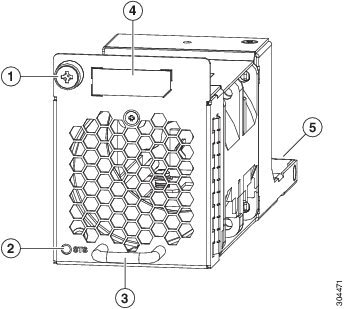
| Step 1 | For a Cisco
Nexus 93128TX, 9396PX, or 9396TX switch, verify that the fan modules that you
are not replacing each have a lit Status (STS) LED (see the following figure
for the location of the LED). If you are replacing a fan module during
operations, the other two fan modules must be operating.
| ||||||||||||||||
| Step 2 | Unscrew the captive screw that secures the fan module to the chassis. | ||||||||||||||||
| Step 3 | Pull the fan
module handle to slide the module out of the chassis.
| ||||||||||||||||
| Step 4 | Place the removed module on an antistatic surface or in an antistatic bag. If possible, repack the module in its packing materials for safe shipping or storage. | ||||||||||||||||
| Step 5 | Follow these
steps to replace the missing fan module within two minutes to avoid a shutdown.
|
Replacing an AC Power Supply
You can replace an AC power supply during operations so long as there is another power supply installed and operating during the replacement. The switch requires only one power supply for operations, so you can hot swap the redundant power supply during operations. If there is only one power supply installed in the chassis, you can replace it by installing the new power supply in the open power supply slot before removing the other power supply.
 Warning | Statement 1034—Backplane Voltage Hazardous voltage or energy is present on the backplane when the system is operating. Use caution when servicing |
 Caution | Be sure that the replacement power supply has the correct direction of airflow, which means that it has the same color markings as the other fan trays and AC power supplies in the chassis (DC power supplies will have green handles). Otherwise, the switch can overheat and shutdown. |
Removing an AC Power Supply
To remove an AC power supply, follow these steps:
-
To replace a power supply during operations, you must have a functioning power supply providing power to the switch while you replace the other power supply. If there is only one power supply installed in the switch and you need to replace it, install the new power supply in the open slot and power it up (see ) before removing the original power supply.
-
Ensure that the chassis is grounded. For grounding instructions, see Grounding the Chassis.
| Step 1 | Pull the power
cord out from the power receptacle on the power supply to be removed and verify
that the
| ||
| Step 2 | Remove the power supply from the chassis by pushing and holding its thumb latch to the left and pulling the power supply part way out of the chassis. | ||
| Step 3 | Place your other
hand under the power supply to support it while you slide it out of the
chassis.
Either place the power supply on an antistatic surface or pack it in its packing materials. | ||
| Step 4 | If the power supply slot is to remain empty, install a blank power supply filler panel (part number N2200-P-BLNK). |
 LED might on and amber colored to indicate that the input power has been
disconnected.
LED might on and amber colored to indicate that the input power has been
disconnected.
What to Do Next
You are ready to install the replacement power supply.
Installing an AC Power Supply
| Step 1 | Ensure that the system (earth) ground connection has been made for the chassis. For ground connection instructions, see Grounding the Chassis. | ||
| Step 2 | If the power supply slot has a filler panel, remove it from the slot by moving its release latch to the left and pulling the panel out of the slot. | ||
| Step 3 | Holding the replacement power supply with one hand underneath the module and the other hand holding the handle, align the back end of the power supply (the end with the electrical connections) to the open power supply slot and slide the power supply all the way into the slot until it clicks into place. | ||
| Step 4 | Test the
installation by trying to pull the power supply out of the slot without using
the release latch.
If the power supply does not move out of place, it is secured in the slot. If the power supply moves, press it all the way into the slot until it clicks in place. | ||
| Step 5 | Attach the power cable to the electrical outlet on the front of the power supply. | ||
| Step 6 | Connect the
other end of the power cable to an AC power source.
| ||
| Step 7 | Verify that the
power supply is operational by checking that the power supply
|
Replacing a DC Power Supply During Operations
You can replace an DC power supply during operations so long as there is another power supply installed and operating during the replacement. The switch requires only one power supply for operations, so you can hot swap the redundant power supply during operations. If there is only one power supply installed in the chassis, you can replace it by installing the new power supply in the open power supply slot and making it operational before removing the other power supply.
Depending on your power redundancy requirement, be sure there are one or two power sources close to the rack:
-
For no power redundancy, use one power source.
-
For power supply redundancy, use one or two power sources.
-
For grid redundancy, use two power sources.
Caution | Be sure that the replacement power supply has the same direction of airflow as the other modules. For port-side intake airflow, the fan and AC power supplies have burgundy coloring and DC power supplies have green coloring. For port-side exhaust airflow, the fan and AC power supplies have blue coloring. |
Warning | Statement 1034—Backplane Voltage Hazardous voltage or energy is present on the backplane when the system is operating. Use caution when servicing |
- Removing a 48 V DC Power Supply
- Installing a 48 V DC Power Supply
- Wiring a 48 V DC Electrical Connector Block
Removing a 48 V DC Power Supply
If the switch has two power supplies, you can replace one power supply while the other one provides power to the switch. If you have only one power supply in the switch, install the replacement power supply in the open slot before removing the original power supply.
| Step 1 | Turn off the
circuit breaker for the power source to the power supply that you are
replacing.
Be sure that the LEDs on the power supply turn off. |
| Step 2 | Remove the power cable connector block from the power supply by doing the following: |
| Step 3 | Grasp the power supply handle while pressing the release latch towards the handle. |
| Step 4 | Pull the power supply out of the bay. |
Installing a 48 V DC Power Supply
If the switch has two power supplies, you can replace one power supply while the other one provides power to the switch. If you have only one power supply in the switch, install the replacement power supply in the open slot before removing the original power supply.
The circuit breaker for the DC power source for the power supply must be turned off.
| Step 1 | Holding the power supply module by its handle, align the back of the module to the empty bay. |
| Step 2 | Push the module into the bay until the release lever clicks and locks the module in place. |
| Step 3 | If the DC power
cables and a grounding cable are already connected to an electrical connector
block, insert the block into the power receptacle on the power supply.
If the electrical cables have not been connected to the electrical connector block, wire them as described in Wiring a 48 V DC Electrical Connector Block. |
| Step 4 | Turn on the circuit breaker for the DC power source connected to the power supply. |
| Step 5 | Verify that the power supply
|
Wiring a 48 V DC Electrical Connector Block
You must connect the ground, negative, and positive DC power cables to a connector block in order to connect the power cables to a 48 V DC power supply.
Note | The recommended wire gauge is 8 AWG. The minimum wire gauge is 10 AWG. |
Warning | Statement 342—Before Connecting to System Power Supply High leakage currentearth connection essential before connecting to system power supply. |
Warning | Statement 1024—Ground Conductor This equipment must be grounded. Never defeat the ground conductor or operate the equipment in the absence of a suitably installed ground conductor. Contact the appropriate electrical inspection authority or an electrician if you are uncertain that suitable grounding is available. |
You must turn off the circuit breaker for the DC power cables that you are connecting to prevent electrocution.
| Step 1 | Verify that the circuit breaker for the DC power source you are connecting is turned off. | ||||||||||||
| Step 2 | Remove the DC power connector block from the power supply by doing the following: | ||||||||||||
| Step 3 | Strip 0.6 inches (15 mm) of insulation off the DC wires that you are using. | ||||||||||||
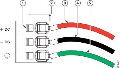
| Step 4 | Orient the
connector as shown in the following figure with the orange plastic button on
top.
| ||||||||||||
| Step 5 | Use a small screwdriver to depress the spring-loaded wire retainer lever on the lower spring-cage wire connector. Insert your green (ground) wire into the aperture and then release the lever. | ||||||||||||
| Step 6 | Use a small screwdriver to depress the spring-loaded wire retainer lever on the middle spring-cage wire connector. Insert your black (DC negative) wire into the aperture and then release the lever. | ||||||||||||
| Step 7 | Use a small screwdriver to depress the spring-loaded wire retainer lever on the upper spring-cage wire connector. Insert your red (DC positive) wire into the aperture and then release the lever. | ||||||||||||
| Step 8 | Insert the connector block back into the power supply. Make sure that your red (DC positive) wire aligns with the power supply label, "+ DC". |
What to Do Next
Verify that the other ends of the cables are attached to the DC power source and ground. You are then ready to turn on the DC power source.
 Feedback