Temperature Requirement
This switch is rated to operate at 32 to 104°F (0 to 40°C). It can be stored at -40 to 158°F (-40 to 70°C).
The documentation set for this product strives to use bias-free language. For the purposes of this documentation set, bias-free is defined as language that does not imply discrimination based on age, disability, gender, racial identity, ethnic identity, sexual orientation, socioeconomic status, and intersectionality. Exceptions may be present in the documentation due to language that is hardcoded in the user interfaces of the product software, language used based on RFP documentation, or language that is used by a referenced third-party product. Learn more about how Cisco is using Inclusive Language.
This switch is rated to operate at 32 to 104°F (0 to 40°C). It can be stored at -40 to 158°F (-40 to 70°C).
High humidity can cause moisture to enter the switch. Moisture can cause corrosion of internal components and degradation of properties such as electrical resistance, thermal conductivity, physical strength, and size. The switch is rated to withstand from 5- to 95-percent (nonoperating) and 5- to 90-percent (operating) relative humidity.
Buildings cooled with air conditioning during warm months and warmed during cold months usually maintain an acceptable level of humidity. However, if the site is unusually humid, use a dehumidifier to maintain the required humidity level.
High-altitude (low-pressure) conditions outside of 0 to 5,000 feet (0 to 1524 m) can reduce the cooling efficiency and cause electrical problems.
To prevent contaminant buildup and increased internal chassis temperatures, make sure that the operating environment is as clean as possible and free of dust and other contaminants. Do not permit smoking, food, or drinks near the switch.
Electromagnetic interference (EMI) and radio frequency interference (RFI) from the switch can adversely affect other devices, such as radio and television (TV) receivers. Radio frequencies that emanate from the switch can also interfere with cordless and low-power telephones. Conversely, RFI from high-power telephones can cause spurious characters to appear on the switch monitor.
RFI is defined as any EMI with a frequency above 10 kHz. This type of interference can travel from the switch to other devices through the power cable and power source or through the air as transmitted radio waves. The Federal Communications Commission (FCC) publishes specific regulations to limit the amount of EMI and RFI that are emitted by computing equipment. Each switch meets these FCC regulations.
To reduce the possibility of EMI and RFI, follow these guidelines:
Cover all open expansion slots with a blank filler plate.
Always use shielded cables with metal connector shells for attaching peripherals to the switch.
When wires are run for any significant distance in an electromagnetic field, interference can occur to the signals on the wires with the following implications:
Bad wiring can result in radio interference emanating from the plant wiring.
Strong EMI, especially when it is caused by lightning or radio transmitters, can destroy the signal drivers and receivers in the chassis and even create an electrical hazard by conducting power surges through lines into equipment.
 Note |
To predict and prevent strong EMI, you need to consult experts in radio frequency interference (RFI). |
The wiring is unlikely to emit radio interference if you use a twisted-pair cable with a good distribution of grounding conductors. If you exceed the recommended distances, use a high-quality twisted-pair cable with one ground conductor for each data signal when applicable.
 Caution |
If the wires exceed the recommended distances, or if wires pass between buildings, give special consideration to the effect of a lightning strike in your vicinity. The electromagnetic pulse that is caused by lightning or other high-energy phenomena can easily couple enough energy into unshielded conductors to destroy electronic switches. You will want to consult experts in electrical surge suppression and shielding if you had similar problems in the past. |
The switch has been shock- and vibration-tested for operating ranges, handling, and earthquake standards.
The switch is sensitive to variations in voltage that is supplied by the power sources. Overvoltage, undervoltage, and transients (or spikes) can erase data from memory or cause components to fail. To protect against these types of problems, ensure that there is an earth-ground connection for the switch. You can connect the grounding pad on the switch either directly to the earth-ground connection or to a fully bonded and grounded rack.
When you properly install the chassis in a grounded rack, the switch is grounded because it has a metal-to-metal connection to the rack. Alternatively, you can ground the chassis by using a customer-supplied grounding cable that meets your local and national installation requirements. For U.S. installations, we recommend 6-AWG wire. Connect your grounding cable to the chassis with a grounding lug (provided in the switch accessory kit) and to the facility ground.
Note |
You automatically ground AC power supplies when you connect them to AC power sources. For DC power supplies, you must connect a grounding wire when wiring the power supply to the DC power source. |
Note |
An electrical conducting path shall exist between the product chassis and the metal surface of the enclosure or rack in which it is mounted or to a grounding conductor. Electrical continuity shall be provided by using thread-forming type mounting screws that remove any paint or non-conductive coatings and establish a metal-to-metal contact. Any paint or other non-conductive coatings shall be removed on the surfaces between the mounting hardware and the enclosure or rack. The surfaces shall be cleaned and an antioxidant applied before installation. |
You can install the following types of racks or cabinets for your switch:
Standard perforated cabinets
Solid-walled cabinets with a roof fan tray (bottom-to-top cooling)
Standard open four-post Telco racks
To install the switch in a cabinet that is located in a hot-aisle and cold-aisle environment, fit the cabinet with baffles to prevent exhaust air from recirculating into the chassis air intake.
Work with your cabinet vendors to determine which of their cabinets meet the following requirements or see the Cisco Technical Assistance Center (TAC) for recommendations:
Use a standard 19-inch (48.3-cm), four-post Electronic Industries Alliance (EIA) cabinet or rack with mounting rails that conform to English universal hole spacing per section 1 of the ANSI/EIA-310-D-1992 standard.
The height of the rack or cabinet must accommodate the 7.1-RU (12.4 inches or 31.6 cm) height of the switch and its bottom support bracket.
The depth of a four-post rack must be 24 to 32 inches (61.0 to 81.3 cm) between the front and rear mounting rails (for proper mounting of the bottom-support brackets or other mounting hardware).
Required clearances between the chassis and the edges of its rack or the interior of its cabinet are as follows:
4.5 inches (11.4 cm) between the front of the chassis and the front of the rack or interior of the cabinet (required for cabling and module handles).
3.0 inches (7.6 cm) between the rear of the chassis and the interior of the cabinet (required for airflow in the cabinet if used).
No clearance is required between the chassis and the sides of the rack or cabinet (no side airflow).
Also, you must consider the following site requirements for the rack:
Also, you must have power receptacles that are located within reach of the power cords that are used with the switch.
 Warning |
Statement 1048—Rack Stabilization The rack stabilizing mechanism must be in place, or the rack must be bolted to the floor before installation or servicing. Failure to stabilize the rack can cause bodily injury. |
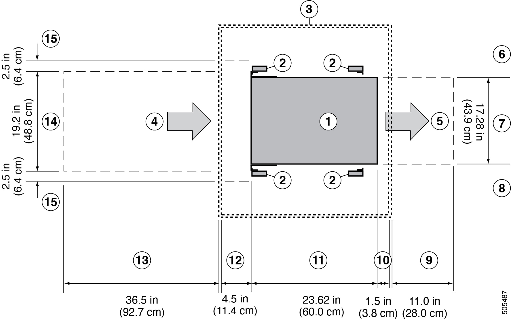
Provide the chassis with adequate clearance between the chassis and any other rack, device, or structure so that you can properly install the chassis. Provide the chassis with adequate clearance to route cables, provide airflow, and maintain the switch. For the clearances required for an installation of this chassis, see the following figure.
|
1 |
Chassis |
9 |
Rear service clearance required to replace fan trays and fabric modules. |
|
2 |
Vertical rack-mount posts and rails |
10 |
Minimum clearance required for module handles (up to 6 inches [15.24 cm] recommended for optimal airflow) when using cabinet doors |
|
3 |
Cabinet (optional) |
11 |
Chassis depth |
|
4 |
Air intake from the cold aisle for all modules and power supplies |
12 |
Recommended clearance for cable management and ejector handles on line cards (6 inches [15.24 cm] recommended for optimal airflow) when using cabinet doors |
|
5 |
Air exhaust to the hot aisle for all modules and power supplies |
13 |
Clearance required for installing the chassis and replacing line cards |
|
6 |
No left-side clearance required (no airflow on the left side). |
14 |
Width of the chassis plus vertical mounting brackets on each side |
|
7 |
Chassis width |
15 |
Side clearance, that is required for older line card handle rotation (not required for the current line cards which have handles that rotate differently). |
|
8 |
No right-side clearance required (no airflow on the right side). |
 Feedback