-
null
Replacing
Components
Replacing a Fan Module
You can replace one of the four fan modules at a time while the switch is operating so long as you perform the replacement within one minute. If you cannot perform the replacement within one minute, leave the original fan module in the chassis to maintain the designed airflow until you have the replacement fan module on hand and can perform the replacement.
 Caution | If you are replacing a module during operations, be sure that the replacement fan module has the correct direction of airflow, which means that it has the same airflow direction as the other modules in the chassis. Also, be sure that the airflow direction takes in air from a cold aisle and exhausts to a hot aisle. Otherwise, the switch can overheat and shutdown. If you are changing the airflow direction of all the modules in the chassis, you must shutdown the switch before replacing all the fan and power supply modules with modules using the other airflow direction. During operations, all of the modules must have the same direction of airflow. |
Removing a Fan Module
 Warning | Statement 263—Fan Warning The fans might still be turning when you remove the fan assembly from the chassis. Keep fingers, screwdrivers, and other objects away from the openings in the fan assembly's housing. |
Installing a Fan Module
-
A fan slot must be open and ready for the new fan module to be installed.
-
You must have a new fan module on hand and ready to install within one minute of removing the original fan module if the switch is operating.
-
The new fan module must have the same airflow direction as the other fan and power supply modules installed in the switch. All of these modules must have either burgundy coloring (port-side intake airflow) or they must all have blue coloring (port-side exhaust airflow).
Replacing a Power Supply Module
The switch requires two power supplies for redundancy. With one power supply providing the necessary power for operations, you can replace the other power supply during operations so long as the new power supply has the same airflow direction as the other modules in the chassis.
 Note | If you need to change the airflow direction of the switch modules, you must shut down the switch before changing all of the modules to modules using the other airflow direction. |
You can replace a power supply with any other power supply that is supported by the same switch so long as it provides the same direction of airflow as the fan modules installed in the switch and uses the same type of power source as the other power supply installed in the switch (do not mix AC, DC, and HVAC/HVDC power supplies in the same switch). The coloring of the latch handle on the power supply indicates the airflow direction as explained in the following table that lists the supported power supplies for this switch.
|
Part Number |
Power Characteristics |
Airflow Direction (Latch Color) |
|---|---|---|
|
N9K-PAC-650W |
650 W, 16 A, AC power source |
Port-side intake (burgundy latch) |
|
N9K-PAC-650W-B |
650 W, 16 A, AC power source |
Port-side exhaust (blue latch) |
|
N9K-PUV-1200W |
1200 W, 16 A, HVAC/HVDC power source |
Dual direction (white latch) (These modules automatically use the same airflow direction as the fan modules installed in the same switch.) |
|
UCSC-PSU-930WDC |
930 W, 16 A, DC power source |
Port-side intake (green latch) |
|
UCS-PSU-6332-DC |
930 W, 16 A, DC power source |
Port-side exhaust (gray latch) |
- Removing an AC Power Supply
- Removing an HVAC/HVDC Power Supply
- Removing a DC Power Supply
- Installing an AC Power Supply
- Installing an HVAC/HVDC Power Supply
- Wiring a 48 V DC Electrical Connector Block
Removing an AC Power Supply
You can remove one power supply while the other one provides power to the switch and install the new power supply in the open slot.
| Step 1 | Holding the plug
for the power cable, pull the plug out from the power receptacle on the power
supply and verify that both power supply LEDs are off.
| ||
| Step 2 | Grasp the power supply handle while pressing the release latch towards the power supply handle. | ||
| Step 3 | Place your other
hand under the power supply to support it while you slide it out of the
chassis.
|
What to Do Next
You are ready to install an AC power supply in the open slot.
Removing an HVAC/HVDC Power Supply
You can remove one power supply while the other one provides power to the switch.
To disconnect the power supply from its power cables, you must shut off the power from the power source and then either disconnect a connector for the power cables or release each of three cables from the power supply (requires a standard screw driver).
| Step 1 | Turn off the circuit breaker for the power feed to the power supply that you are replacing.
Be sure that the LEDs turn off on the power supply that you are removing. | ||
| Step 2 | Remove the power cable from the power supply by pressing the tab on the top of the Anderson Power SAF-D-Grid connector and pull the cable and connector out of the power supply. | ||
| Step 3 | Grasp the power supply handle while pressing the release latch towards the power supply handle. | ||
| Step 4 | Place your other hand under the power supply to support it while you slide it out of the chassis.
|
What to Do Next
You are ready to install an HVAC/HVDC power supply in the open slot.
Removing a DC Power Supply
You can remove one power supply while the other one provides power to the switch.
To disconnect the power supply from its power cables, you must shut off the power from the power source and then either disconnect a connector for the power cables or release each of three cables from the power supply (requires a standard screw driver).
| Step 1 | Turn off the circuit breaker for the power feed to the power supply that you are replacing.
Be sure that the LEDs turn off on the power supply that you are removing. |
| Step 2 | Remove the power cable from the power supply by doing the following: |
| Step 3 | Grasp the power supply handle while pressing the release latch towards the power supply handle. |
| Step 4 | Pull the power supply out of the bay. |
What to Do Next
You are ready to install a DC power supply in the open slot.
Installing an AC Power Supply
You can replace one power supply while the other one provides power to the switch.
-
The power supply that you are installing must be capable of using the same airflow direction as the fan trays installed in the same switch and it must use the same type of power source as the other power supply installed in the same switch (do not mix AC and DC power supplies in the same switch).
-
An AC power source must be within reach of the power cable that will be used with the replacement power supply. If you are using n+n power redundancy, there must be a separate power source for each power supply installed in the chassis. Otherwise, only one power source is required.
-
There must be an earth ground connection to the chassis that you are installing the replacement module. Typically, the chassis is grounded by its metal-to-metal connection with a grounded rack. If you need to ground the chassis, see Grounding the Chassis.
| Step 1 | Holding the replacement power supply with one hand underneath the module and the other hand holding the handle, turn the power supply so that its release latch is on the right side and align the back end of the power supply (the end with the electrical connections) to the open power supply slot before carefully sliding the power supply all the way into the slot until it clicks into place.
| ||
| Step 2 | Test the
installation by trying to pull the power supply out of the slot without using
the release latch.
If the power supply does not move out of place, it is secured in the slot. If the power supply moves, carefully press it all the way into the slot until it clicks in place. | ||
| Step 3 | Attach the power cable to the electrical outlet on the front of the power supply. | ||
| Step 4 | Make sure that
the other end of the power cable is attached to the appropriate power source
for the power supply.
| ||
| Step 5 | Verify that the power supply is operational by making sure that the power supply |
Installing an HVAC/HVDC Power Supply
You can replace one power supply while the other one provides power to the switch.
-
If you are using DC power for the replacement power supply, the circuit breaker for the power feed to the power supply that you are replacing must be turned off.
-
If you are using n+n power redundancy, there must be a separate power source for each power supply installed in the chassis (power sources must be of the same type--do not mix AC and DC power sources for the same switch). Otherwise, only one power source is required.
-
There must be an earth ground connection to the chassis that you are installing the replacement module. Typically, the chassis is grounded by its metal-to-metal connection to a grounded rack. If you need to ground this chassis by another means, see Grounding the Chassis.
| Step 1 | Holding the replacement power supply with one hand underneath the module and the other hand holding the handle, turn the power supply so that its release latch is on the right side and align the back end of the power supply (the end with the electrical connections) to the open power supply slot before carefully sliding the power supply all the way into the slot until it clicks into place.
| ||
| Step 2 | Test the installation by trying to pull the power supply out of
the slot without using the release latch.
If the power supply does not move out of place, it is secured in the slot. If the power supply moves, carefully press it all the way into the slot until it clicks in place. | ||
| Step 3 | If the DC power
cables and a grounding cable are already connected to an electrical connector
block, insert the block into the power receptacle on the power supply.
If the electrical cables have not been connected to the electrical connector block, wire them as described in Wiring a 48 V DC Electrical Connector Block. | ||
| Step 4 | Make sure that the other end of the power cable is connected to the appropriate power source for the power supply. | ||
| Step 5 | If using a DC power source, turn on the circuit breaker for the DC power source connected to the power supply. | ||
| Step 6 | Verify that the power supply is operational by making sure that the power supply |
Wiring a 48 V DC Electrical Connector Block
You must connect the ground, negative, and positive DC power cables to a connector block in order to connect the power cables to a 48 V DC power supply.
Note | The recommended wire gauge is 8 AWG. The minimum wire gauge is 10 AWG. |
Warning | Statement 342—Before Connecting to System Power Supply High leakage currentearth connection essential before connecting to system power supply. |
Warning | Statement 1024—Ground Conductor This equipment must be grounded. Never defeat the ground conductor or operate the equipment in the absence of a suitably installed ground conductor. Contact the appropriate electrical inspection authority or an electrician if you are uncertain that suitable grounding is available. |
You must turn off the circuit breaker for the DC power cables that you are connecting to prevent electrocution.
| Step 1 | Verify that the circuit breaker for the power feed to the replacement power supply is turned off. | ||||||||||||
| Step 2 | Remove the DC power connector block from the power supply by doing the following: | ||||||||||||
| Step 3 | Strip 0.6 inches (15 mm) of insulation off the DC wires that you are using. | ||||||||||||
| Step 4 | Orient the
connector as shown in the following figure with the orange plastic button on
top.
| ||||||||||||
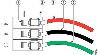
| Step 5 | Use a small screwdriver to depress the spring-loaded wire retainer lever on the lower spring-cage wire connector. Insert your green (ground) wire into the aperture and then release the lever. | ||||||||||||
| Step 6 | Use a small screwdriver to depress the spring-loaded wire retainer lever on the middle spring-cage wire connector. Insert your black (DC negative) wire into the aperture and then release the lever. | ||||||||||||
| Step 7 | Use a small screwdriver to depress the spring-loaded wire retainer lever on the upper spring-cage wire connector. Insert your red (DC positive) wire into the aperture and then release the lever. | ||||||||||||
| Step 8 | Insert the connector block back into the power supply. Make sure that your red (DC positive) wire aligns with the power supply label, "+ DC". | ||||||||||||
| Step 9 | Verify that the other ends of the cables are attached to the DC power source and ground. You are then ready to turn on the DC power source. |
 Feedback