Cisco Nexus 5500 Series NX-OS Fibre Channel over Ethernet Configuration Guide, Release 6.x
Bias-Free Language
The documentation set for this product strives to use bias-free language. For the purposes of this documentation set, bias-free is defined as language that does not imply discrimination based on age, disability, gender, racial identity, ethnic identity, sexual orientation, socioeconomic status, and intersectionality. Exceptions may be present in the documentation due to language that is hardcoded in the user interfaces of the product software, language used based on RFP documentation, or language that is used by a referenced third-party product. Learn more about how Cisco is using Inclusive Language.
- Updated:
- July 30, 2013
Chapter: Configuring FCoE
Configuring FCoE
This chapter contains the following sections:
- FCoE Topologies
- FCoE Best Practices
- Guidelines and Limitations
- Configuring FCoE
- Verifying the FCoE Configuration
FCoE Topologies
Directly Connected CNA Topology
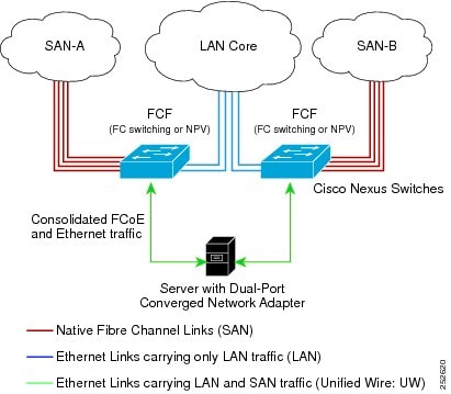
The Cisco Nexus device can be deployed as a Fibre Channel Forwarder (FCF) as shown in the following figure.

The following rules are used to process FIP frames to avoid the FCF being used as a transit between an FCoE node (ENode) and another FCF. These rules also prevent login sessions between ENodes and FCFs in different fabrics.
-
FIP solicitation and login frames received from the CNAs are processed by the FCF and are not forwarded.
-
If an FCF receives solicitations and advertisements from other FCFs over an interface, the following occurs:
CNAs cannot discover or log in to FCFs that are reachable only through a transit Cisco Nexus FCF. The Cisco Nexus device cannot perform the FCoE transit function between a CNA and another FCF due to hardware limitations.
Because the Cisco Nexus FCF cannot perform the transit FCoE function, you must design your network topology so that the active Spanning Tree Protocol (STP) path of FCoE VLANs is always over the directly connected links between the CNA and the FCF. Make sure that you configure the FCoE VLAN on the directly connected links only.
Remotely Connected CNA Topology
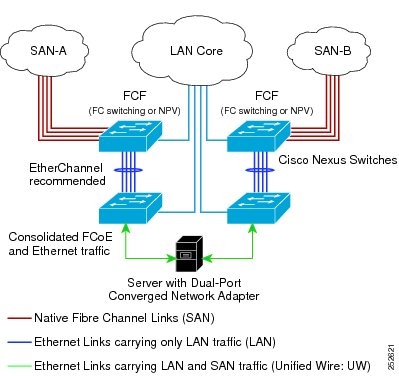
The Cisco Nexus device can be deployed as a Fibre Channel Forwarder (FCF) for remotely connected CNAs, but not as a FIP snooping bridge, as shown in the following figure.

The following rules are used to process FIP frames to avoid the FCF being used as a transit between an ENode and another FCF. These rules also prevent login sessions between ENodes and FCFs in different fabrics.
-
FIP solicitation and login frames received from the CNAs are processed by the FCF and are not forwarded.
-
If an FCF receives solicitations and advertisements from other FCFs over an interface, the following occurs:
Because the Cisco Nexus FCF cannot perform the transit FCoE function, you must design your network topology so that the active STP path of FCoE VLANs is always over the directly connected links between the CNA and the FCF. Make sure that you configure the FCoE VLAN on the directly connected links only.
FCoE Best Practices
Directly Connected CNA Best Practice
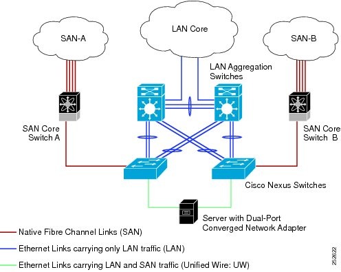
The following figure shows a best practices topology for an access network that is using directly connected CNAs with Cisco Nexus devices.

Follow these configuration best practices for the deployment topology in the preceding figure:
-
You must configure a unique dedicated VLAN at every converged access switch to carry traffic for each Virtual Fabric (VSAN) in the SAN (for example, VLAN 1002 for VSAN 1, VLAN 1003 for VSAN 2, and so on). If you enable Multiple Spanning Tree (MST), you must use a separate MST instance for FCoE VLANs.
-
You must configure the unified fabric (UF) links as trunk ports. Do not configure the FCoE VLAN as a native VLAN. You must configure all FCoE VLANs as members of the UF links to allow extensions for VF_Port trunking and VSAN management for the virtual Fibre Channel interfaces.

Note
A unified wire carries both Ethernet and FCoE traffic.
-
You must configure the UF links as spanning-tree edge ports.
-
You must not configure the FCoE VLANs as members of Ethernet links that are not designated to carry FCoE traffic because you want to ensure that the scope of the STP for the FCoE VLANs is limited to UF links only.
-
If the converged access switches (in the same SAN fabric or in another) need to be connected to each other over Ethernet links for a LAN alternate path, you must explicitly configure such links to exclude all FCoE VLANs from membership. This action ensures that the scope of the STP for the FCoE VLANs is limited to UF links only.
-
You must use separate FCoE VLANs for FCoE in SAN-A and SAN-B.
 Note | All Gen-1 (pre-FIP) and Gen-2 (FIP) CNAs are supported in a directly connected topology. |
Remotely Connected CNA Best Practice
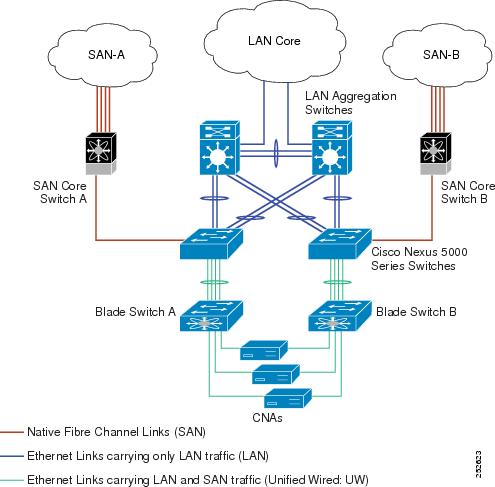
The following figure shows a best practices topology for an access network using remotely connected CNAs with Cisco Nexus devices.

Follow these configuration best practices for the deployment topology in the preceding figure:
-
You must configure a unique dedicated VLAN at every converged access switch to carry traffic for each Virtual Fabric (VSAN) in the SAN (for example, VLAN 1002 for VSAN 1, VLAN 1003 for VSAN 2, and so on). If you enable MST, you must use a separate MST instance for FCoE VLANs.
-
You must configure the unified fabric (UF) links as trunk ports. Do not configure the FCoE VLAN as a native VLAN. You must configure all FCoE VLANs as members of the UF links to allow extensions for VF_Port trunking and VSAN management for the virtual Fibre Channel interfaces.

Note
A unified fabric link carries both Ethernet and FCoE traffic.
-
You must configure the CNAs and the blade switches as spanning-tree edge ports.
-
A blade switch must connect to exactly one Cisco Nexus device converged access switch, preferably over an EtherChannel, to avoid disruption due to STP reconvergence on events such as provisioning new links or blade switches.
-
You must configure the Cisco Nexus device converged access switch with a better STP priority than the blade switches that are connected to it. This requirement allows you to create an island of FCoE VLANs where the converged access switch is the spanning-tree root and all the blade switches connected to it become downstream nodes.
-
Do not configure the FCoE VLANs as members of Ethernet links that are not designated to carry FCoE traffic because you want to ensure that the scope of the STP for the FCoE VLANs is limited to UF links only.
-
If the converged access switches and/or the blade switches need to be connected to each over Ethernet links for the purposes of LAN alternate pathing, you must explicitly configure such links to exclude all FCoE VLANs from membership. This action ensures the scope of the STP for FCoE VLANs is limited to UF links only.
-
You must use separate FCoE VLANs for FCoE in SAN-A and SAN-B.
 Note | A remotely connected topology is supported only with Gen-2 (FIP) CNAs. |
Guidelines and Limitations
FCoE has the following guidelines and limitations:
-
FCoE on Cisco Nexus devices support the Gen-1 (pre-FIP) and Gen-2 (FIP) CNAs. FCoE on the Cisco Nexus 2232PP fabric extender (FEX) supports Gen-2 CNAs only.
-
Enabling FCoE on VLAN 1 is not supported.
-
A combination of straight-through and active-active topologies is not supported on the same FEX.
-
Direct connect FCoE (that is, a direct connect to CNAs through a bind interface) is not supported on a port channel of a Cisco Nexus device or FEX interface if it is configured to have more than one interface. Direct connect FCoE is supported on port channels with a single link to allow for FCoE from a CNA connected through a vPC with one 10 GB link to each upstream switch/FEX.
 Note | For a description of the default quality of service (QoS) policies for FCoE, see the Quality of Service guide for your device. for the Nexus software release that you are using. The available versions of this document can be found at the following URL: http://www.cisco.com/en/US/products/ps9670/products_installation_and_configuration_guides_list.html.. |
Configuring FCoE
Configuring QoS
You need to attach the system service policy to configure QoS. The service-policy command specifies the system class policy map as the service policy for the system.
Enabling FCoE
You can enable FCoE on the switch; however, enabling FCoE on VLAN 1 is not supported.
 Note | All the Fibre Channel features of the Cisco Nexus device are packaged in the FC Plugin. When you enable FCoE, the switch software checks for the FC_FEATURES_PKG license. If it finds the license, the software loads the plugin. If the license is not found, the software loads the plugin with a grace period of 180 days. After the FC Plugin is loaded, the following occurs:
If after 180 days, a valid license is not found, the FC Plugin is disabled. At the next switch reboot, all FCoE commands are removed from the CLI and the FCoE configuration is deleted. |
You must have the FC_FEATURES_PKG (N5010SS or N5020SS) license installed.
| Command or Action | Purpose |
|---|
This example shows how to enable FCoE on the switch:
switch# configure terminal
switch(config)# feature fcoe
Disabling FCoE
After you disable FCoE, all FCoE commands are removed from the CLI and the FCoE configuration is deleted.
| Command or Action | Purpose |
|---|
This example shows how to disable FCoE on the switch:
switch# configure terminal
switch(config)# no feature fcoe
Disabling LAN Traffic on an FCoE Link
You can disable LAN traffic on an FCoE link.
DCBX allows the switch to send a LAN Logical Link Status (LLS) message to a directly connected CNA. Enter the shutdown lan command to send an LLS-Down message to the CNA. This command causes all VLANs on the interface that are not enabled for FCoE to be brought down. If a VLAN on the interface is enabled for FCoE, it continues to carry SAN traffic without any interruption.
| Command or Action | Purpose | |
|---|---|---|
| Step 1 | switch# configure terminal |
Enters global configuration mode. |
| Step 2 |
switch(config)#
interface
ethernet
slot/port
|
Specifies an interface to configure, and enters interface configuration mode. |
| Step 3 | switch(config-if)#
shutdown
lan
|
Shuts down Ethernet traffic on the interface. If the interface is part of an FCoE VLAN, the shutdown has no impact on the FCoE traffic. |
| Step 4 | switch(config-if)#
no shutdown
lan
| (Optional)
Reenables Ethernet traffic on the interface. |
Configuring the FC-Map
 Note | We recommend using the "Mapping a VSAN to a VLAN" method for preserving fabric isolation and leaving the FC-MAP default. |
You can prevent data corruption due to cross-fabric talk by configuring an FC-Map that identifies the Fibre Channel fabric for this Cisco Nexus device. When the FC-Map is configured, the switch discards the MAC addresses that are not part of the current fabric.
| Command or Action | Purpose | |
|---|---|---|
| Step 1 | switch# configure terminal |
Enters global configuration mode. |
| Step 2 |
switch(config)#
fcoe
fcmap
fabric-map
|
Configures the global FC-Map. The default value is 0E.FC.00. The range is from 0E.FC.00 to 0E.FC.FF. |
| Step 3 |
switch(config)#
no fcoe
fcmap
fabric-map
| (Optional)
Resets the global FC-Map to the default value of 0E.FC.00. |
This example shows how to configure the global FC-Map:
switch# configure terminal
switch(config)# fcoe fcmap 0x0efc2a
Configuring the Fabric Priority
The Cisco Nexus device advertises its priority. The priority is used by the CNAs in the fabric to determine the best switch to connect to.
| Command or Action | Purpose | |
|---|---|---|
| Step 1 | switch# configure terminal |
Enters global configuration mode. |
| Step 2 |
switch(config)#
fcoe
fcf-priority
fabric-priority
|
Configures the global fabric priority. The default value is 128. The range is from 0 (higher) to 255 (lower). |
| Step 3 |
switch(config)#
no fcoe
fcf-priority
fabric-priority
| (Optional)
Resets the global fabric priority to the default value of 128. |
This example shows how to configure the global fabric priority:
switch# configure terminal
switch(config)# fcoe fcf-priority 42
Configuring Jumbo MTU
This example shows how to configure the default Ethernet system class to support the jumbo MTU:
switch(config)# policy-map type network-qos jumbo
switch(config-pmap-nq)# class type network-qos class-fcoe
switch(config-pmap-c-nq)# pause no-drop
switch(config-pmap-c-nq)# mtu 2158
switch(config-pmap-nq)# class type network-qos class-default
switch(config-pmap-c-nq)# mtu 9216
switch(config-pmap-c-nq)# exit
switch(config-pmap-nq)# exit
switch(config)# system qos
switch(config-sys-qos)# service-policy type qos input fcoe-default-in-policy
switch(config-sys-qos)# service-policy type queuing input fcoe-default-in-policy
switch(config-sys-qos)# service-policy type queuing output fcoe-default-out-policy
switch(config-sys-qos)# service-policy type network-qos jumbo
Setting the Advertisment Interval
You can configure the interval for Fibre Channel fabric advertisement on the switch.
| Command or Action | Purpose | |
|---|---|---|
| Step 1 | switch# configure terminal |
Enters global configuration mode. |
| Step 2 |
switch(config)#
fcoe
fka-adv-period
inverval
|
Configures the advertisement interval for the fabric. The default value is 8 seconds. The range is from 4 to 60 seconds. |
| Step 3 |
switch(config)#
no fcoe
fka-adv-period
interval
| (Optional)
Resets the advertisement interval for the fabric to its default value of 8 seconds. |
This example shows how to configure the advertisement interval for the fabric:
switch# configure terminal
switch(config)# fcoe fka-adv-period 42
Verifying the FCoE Configuration
To verify FCoE configuration information, perform one of these tasks:
|
Command |
Purpose |
|---|---|
| switch# show fcoe |
Displays whether FCoE is enabled on the switch. |
| switch# show fcoe database |
Displays the contents of the FCoE database. |
| switch# show interface [interface number] fcoe |
Displays the FCoE settings for an interface or all interfaces. |
| switch# show queuing interface[interface slot/port] |
Displays the queue configuration and statistics. |
| switch# show policy-map interface[interface number] |
Displays the policy map settings for an interface or all interfaces. |
This example shows how to verify that the FCoE capability is enabled:
switch# show fcoe
Global FCF details
FCF-MAC is 00:0d:ec:6d:95:00
FC-MAP is 0e:fc:00
FCF Priority is 128
FKA Advertisement period for FCF is 8 seconds
This example shows how to display the FCoE database:
switch# show fcoe database
-------------------------------------------------------------------------------
INTERFACE FCID PORT NAME MAC ADDRESS
-------------------------------------------------------------------------------
vfc3 0x490100 21:00:00:1b:32:0a:e7:b8 00:c0:dd:0e:5f:76
This example shows how to display the FCoE settings for an interface.
switch# show interface ethernet 1/37 fcoe
Ethernet1/37 is FCoE UP
vfc3 is Up
FCID is 0x490100
PWWN is 21:00:00:1b:32:0a:e7:b8
MAC addr is 00:c0:dd:0e:5f:76
 Feedback