Cisco Nexus 5500 Series NX-OS FabricPath Configuration Guide, Release 7.x
Bias-Free Language
The documentation set for this product strives to use bias-free language. For the purposes of this documentation set, bias-free is defined as language that does not imply discrimination based on age, disability, gender, racial identity, ethnic identity, sexual orientation, socioeconomic status, and intersectionality. Exceptions may be present in the documentation due to language that is hardcoded in the user interfaces of the product software, language used based on RFP documentation, or language that is used by a referenced third-party product. Learn more about how Cisco is using Inclusive Language.
- Updated:
- January 6, 2015
Chapter: Configuring FabricPath Interfaces
- Information About FabricPath Interfaces
- Guidelines and Limitations for FabricPath Interfaces
- Configuring FabricPath Interfaces
- Verifying the FabricPath Interface Configuration
- Monitoring FabricPath Interface Statistics
- Configuration Example for FabricPath Interface
- Feature History for Configuring FabricPath Interfaces
Configuring FabricPath Interfaces
This chapter describes how to configure the FabricPath interfaces on the Cisco NX-OS 5500 Series switches.
This chapter includes the following sections:
- Information About FabricPath Interfaces
- Guidelines and Limitations for FabricPath Interfaces
- Configuring FabricPath Interfaces
- Verifying the FabricPath Interface Configuration
- Monitoring FabricPath Interface Statistics
- Configuration Example for FabricPath Interface
- Feature History for Configuring FabricPath Interfaces

Note![]() For information about prerequisites, guidelines and limitations, and licensing requirements for FabricPath, see Chapter1, “Overview”
For information about prerequisites, guidelines and limitations, and licensing requirements for FabricPath, see Chapter1, “Overview”
Information About FabricPath Interfaces
This section includes the following sections:
FabricPath Interfaces
After you enable FabricPath on the switches that you are using, you can configure an Ethernet interface or a port-channel interface as a FabricPath interface. If one member of the port channel is in FabricPath mode, all the other members will be in FabricPath mode. After you configure the interface as a FabricPath interface, it automatically becomes a trunk port, capable of carrying traffic for multiple VLANs. You can also configure all the ports on the switch as FabricPath interfaces simultaneously.
The following interface modes carry traffic for the following types of VLANs:
- Interfaces on the switch that are configured as FabricPath interfaces can carry traffic only for FabricPath VLANs.
- Interfaces on the switch that are not configured as FabricPath interfaces carry traffic for the following:
–![]() Classical Ethernet (CE) VLANs
Classical Ethernet (CE) VLANs
See “Configuring FabricPath Forwarding,” for information about FabricPath and CE VLANs.
The FabricPath interfaces connect only to other FabricPath interfaces within the FabricPath network. These FabricPath ports operate on the information in the FabricPath headers and Layer 2 Intermediate System-to-Intermediate System (IS-IS) only, and they do not run STP. These ports are aware only of FabricPath VLANs; they are unaware of any CE VLANs. By default, all VLANs are allowed on a trunk port, so the FabricPath interface carries traffic for all FabricPath VLANs.
STP and the FabricPath Network
The Layer 2 gateway switches, which are on the edge between the CE and the FabricPath network, must be configured as the root for all Spanning Tree Protocol (STP) domains that are connected to a FabricPath network.
The STP domains do not cross into the FabricPath network (see Figure 3-1).
Figure 3-1 STP Boundary Termination at FabricPath Network Border
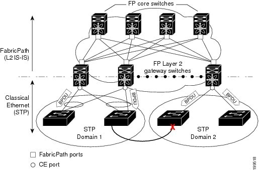
You must configure the FabricPath Layer 2 gateway switch to have the lowest STP priority of all the switches in the STP domain to which it is attached. You must also configure all the FabricPath Layer 2 gateway switches that are connected to one FabricPath network to have the same priority. The software assigns the bridge ID for the Layer 2 gateway switches from a pool of reserved MAC addresses.
To ensure a loop-free topology for the CE and FabricPath hybrid network, the FabricPath network automatically displays as a single bridge to all connected CE switches.
Note![]() You must set the STP priority on all FabricPath Layer 2 gateway switches to a value low enough to ensure that they become root for any attached STP domains.
You must set the STP priority on all FabricPath Layer 2 gateway switches to a value low enough to ensure that they become root for any attached STP domains.
Other than configuring the STP priority on the FabricPath Layer 2 gateway switches, you do not need to configure anything for the STP to work seamlessly with the FabricPath network. Only connected CE switches form a single STP domain. Those CE switches that are not interconnected form separate STP domains (see Figure 3-1).
All CE interfaces should be designated ports, which occurs automatically, or they are pruned from the active STP topology. If the software prunes any port, the software returns a syslog message. The software clears the port again only when that port is no longer receiving superior BPDUs.
The FabricPath Layer 2 gateway switch also propagates the Topology Change Notifications (TCNs) on all its CE interfaces.
The FabricPath Layer 2 gateway switches terminate STP. The set of FabricPath Layer 2 gateway switches that are connected by STP forms the STP domain. Because many FabricPath Layer 2 gateway switches might be attached to a single FabricPath network, there might also be many separate STP domains (see Figure 3-1). The switches in the separate STP domains need to know the TCN information only for the domain to which they belong. You can configure a unique STP domain ID for each separate STP domain that connects to the same FabricPath network. The Layer 2 IS-IS messages carry the TCNs across the FabricPath network. Only those FabricPath Layer 2 gateway switches in the same STP domain as the TCN message need to act and propagate the message to connected CE switches.
When a FabricPath Layer 2 gateway switch receives a TCN for the STP domain it is part of, it takes the following actions:
- Flushes all remote MAC addresses for that STP domain and the MAC addresses on the designated port.
- Propagates the TCN to the other switches in the specified STP domain.
The switches in the separate STP domains need to receive the TCN information and then flush all remote MAC addresses reachable by the STP domain that generated the TCN information.
vPC+
A virtual port channel+ (vPC+) domain allows a classical Ethernet (CE) vPC domain and a Cisco FabricPath cloud to interoperate. A vPC+ also provides a First Hop Routing Protocol (FHRP) active-active capability at the FabricPath to Layer 3 boundary.
Note![]() vPC+ is an extension to virtual port channels (vPCs) that run CE only (see the “Configuring vPCs” chapter in the Cisco Nexus 5500 Series NX-OS Interfaces Configuration Guide, Release 7.x). You cannot configure a vPC+ domain and a vPC domain on the same Cisco Nexus 5500 Series switch.
vPC+ is an extension to virtual port channels (vPCs) that run CE only (see the “Configuring vPCs” chapter in the Cisco Nexus 5500 Series NX-OS Interfaces Configuration Guide, Release 7.x). You cannot configure a vPC+ domain and a vPC domain on the same Cisco Nexus 5500 Series switch.
A vPC+ domain enables Cisco Nexus 5500 Series switches that have FabricPath enabled to form a single vPC+, which is a unique virtual switch to the rest of the FabricPath network. You configure the same domain on each switch to enable the peers to identify each other and to form the vPC+. Each vPC+ has its own virtual switch ID.
Note![]() We do not recommend that you enable the vPC peer switch feature when you are using a vPC+.
We do not recommend that you enable the vPC peer switch feature when you are using a vPC+.
A vPC+ must still provide active-active Layer 2 paths for dual-homed CE switches or clouds, even though the FabricPath network allows only 1-to-1 mapping between the MAC address and the switch ID. vPC+ provides the solution by creating a unique virtual switch to the FabricPath network (see Figure 3-2).
Figure 3-2 Comparison of vPC and vPC+
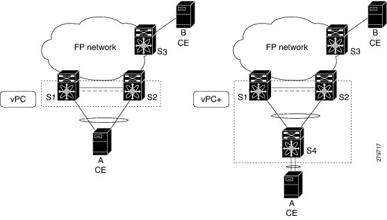
The FabricPath switch ID for the virtual switch becomes the outer source MAC address (OSA) in the FabricPath encapsulation header. Each vPC+ domain must have its own virtual switch ID.
Layer 2 multipathing is achieved by emulating a single virtual switch. Packets forwarded from host A to host B are sent to the MAC address of the virtual switch as the transit source, and traffic from host B to host A is now load balanced.
The vPC+ downstream links are FabricPath edge interfaces that connect to the CE hosts.
The First Hop Routing Protocols (FHRPs), which include the Hot Standby Routing Protocol (HSRP) and the Virtual Router Redundancy Protocol (VRRP), interoperate with a vPC+. You should dual-attach all Layer 3 switches to both vPC+ peer switches.
Note![]() You must enable the Layer 3 connectivity from each vPC+ peer switch by configuring a VLAN network interface for the same VLAN from both switches.
You must enable the Layer 3 connectivity from each vPC+ peer switch by configuring a VLAN network interface for the same VLAN from both switches.
Both the primary and secondary vPC+ switches forward traffic, but only the primary FHRP switch responds to ARP requests.
To simplify initial configuration verification and vPC+/HSRP troubleshooting, you can configure the primary vPC+ peer switch with the FHRP active router highest priority.
In addition, you can use the priority command in the if-hsrp configuration mode to configure failover thresholds for when a group state enabled on a vPC+ peer is in standby or in listen state. You can configure lower and upper thresholds to prevent the group state flap, if there is an interface flap (this feature is useful when there is more than one tracking object per group).
When the primary vPC+ peer switch fails over to the secondary vPC+ peer switch, the FHRP traffic continues to flow seamlessly.
You should configure a separate Layer 3 link for routing from the vPC+ peer switches, rather than using a VLAN network interface for this purpose.

The HSRP use-bia is not supported with a vPC+. When you are configuring custom MAC addresses, you must configure the same MAC address on both vPC+ peer switches.
You can configure a restore timer that delays the vPC+ coming back up until after the peer adjacency forms and the VLAN interfaces are back up. This feature allows you to avoid packet drops if the routing tables do not converge before the vPC+ is once again passing traffic.
Use the delay restore command to configure this feature.
See the Cisco Nexus 5500 Series NX-OS Unicast Routing Configuration Guide, Release 7.x for more information on FHRPs and routing.
Anycast HSRP
Cisco NX-OS provides a way to facilitate further scalability at the spine layer providing support for more than two nodes. You can create an anycast bundle that is an association between a set of VLANs and an anycast switch ID. An anycast switch ID is the same as an emulated switch ID except the anycast switch ID is shared across more than two gateways. The set of VLANs or HSRP group elects an active router and a standby router. The remaining routers in the group are in listen state.
The active HSRP router advertises the anycast switch ID as the source switch ID in FabricPath IS-IS. The leaf switches learn that the anycast switch ID is reachable by all of the routers in the group.
Cisco NX-OS supports a maximum of four gateways. All the first-hop gateways at the spine layer must function in active-active forwarding mode. IP packets are received by any of the spine switches with the destination set as the gateway MAC address and these packets are terminated and locally forwarded.
Guidelines and Limitations for FabricPath Interfaces
FabricPath has the following configuration guidelines and limitations:
Configuring FabricPath Interfaces
You must configure FabricPath interfaces on all switches that are enabled for FabricPath.

Tip![]() If you cannot see any of these commands, verify that you have installed and enabled the FabricPath feature set.
If you cannot see any of these commands, verify that you have installed and enabled the FabricPath feature set.
This section includes the following topics:
- Configuring FabricPath Interfaces
- Configuring the STP Priority with Rapid PVST+
- Configuring the STP Priority with MST
- Configuring the STP Domain ID for STP Domains Connected to the Layer 2 Gateway Switch (Optional)
- Configuring a vPC+ Switch ID
- Configuring an Anycast HSRP Bundle
Configuring FabricPath Interfaces
You must configure the interfaces for the FabricPath network as FabricPath interfaces.
BEFORE YOU BEGIN
Ensure that you have installed and enabled the FabricPath feature on all switches.
SUMMARY STEPS
2.![]() interface [ ethernet slot/port | port-channel channel-no ]
interface [ ethernet slot/port | port-channel channel-no ]
3.![]() fabricpath topology topology-number
fabricpath topology topology-number
4.![]() [ no ] switchport mode fabricpath
[ no ] switchport mode fabricpath
DETAILED STEPS
This example shows how to configure specified interfaces as FabricPath interfaces:
Configuring the STP Priority with Rapid PVST+
All Layer 2 gateway switches must have the same bridge priority when they are in the same STP domain. Make sure that the STP priority configured for the Layer 2 gateway switches on a FabricPath network is the lowest value in the Layer 2 network. Additionally, the priorities must match.
We recommend that you configure the STP priority on all FabricPath Layer 2 gateway switches to 8192.
BEFORE YOU BEGIN
Ensure that you have installed and enabled the FabricPath feature on all switches.
SUMMARY STEPS
2.![]() spanning-tree pseudo-information
spanning-tree pseudo-information
3.![]() spanning-tree vlan [ vlan-id ] priority [ value ]
spanning-tree vlan [ vlan-id ] priority [ value ]
DETAILED STEPS
This example shows how to configure the Rapid PVST+ VLANs on the FabricPath Layer 2 gateway switches to have an STP priority of 8192:
See the Cisco Nexus 5500 Series NX-OS Layer 2 Switching Configuration Guide, Release 7.x for more information on this command.
Configuring the STP Priority with MST
All Layer 2 gateway switches must have the same bridge priority when they are in the same STP domain. Make sure that the STP priority configured for the Layer 2 gateway switches on a FabricPath network is the lowest value in the Layer 2 network. Additionally, the priorities must match.
We recommend that you configure the STP priority for all Multiple Spanning-Tree (MST) instances on all FabricPath Layer 2 gateway switches to 8192.
BEFORE YOU BEGIN
Ensure that you have installed and enabled the FabricPath feature on all switches.
SUMMARY STEPS
2.![]() spanning-tree pseudo-information
spanning-tree pseudo-information
3.![]() spanning-tree mst [ instance-id ] priority [ value ]
spanning-tree mst [ instance-id ] priority [ value ]
DETAILED STEPS
This example shows how to configure the MST instances on the FabricPath Layer 2 gateway switches to have an STP priority of 8192:
See the Cisco Nexus 5500 Series NX-OS Layer 2 Switching Configuration Guide, Release 7.x for more information on this command.
Configuring the STP Domain ID for STP Domains Connected to the Layer 2 Gateway Switch (Optional)
Because there can be many FabricPath Layer 2 gateway switches attached to a single FabricPath network, there are also many separate STP domains that are each connected to a Layer 2 gateway switch. You can configure a unique STP domain ID in the FabricPath network to propagate TCNs across all the STP domains that are connected to the FabricPath network. This configuration ensures that all MAC addresses are flushed when the software receives a TCN.
BEFORE YOU BEGIN
Ensure that you have installed and enabled the FabricPath feature on all switches.
SUMMARY STEPS
2.![]() spanning-tree domain domain-id
spanning-tree domain domain-id
DETAILED STEPS
This example shows how to configure the STP domain ID attached to the FabricPath Layer 2 gateway switch:
Configuring a vPC+ Switch ID
You can configure a vPC+ switch ID.
Note![]() The vPC+ virtual SID cannot be the same as the FabricPath SID for the switch.
The vPC+ virtual SID cannot be the same as the FabricPath SID for the switch.
BEFORE YOU BEGIN
SUMMARY STEPS
DETAILED STEPS
This example shows how to configure a vPC+ switch ID on each vPC+ peer switch:
See the Cisco Nexus 5500 Series NX-OS Interfaces Configuration Guide, Release 7.x for complete information on configuring vPCs.
Configuring an Anycast HSRP Bundle
You can create an anycast bundle that is an association between a set of VLANs and an anycast switch ID.
BEFORE YOU BEGIN
DETAILED STEPS
This example shows how to configure an anycast bundle for a selection of VLANs:
switch(config-anycast-bundle)# switch-id 1300
switch(config-anycast-bundle)# vlan 1, 20-30
switch(config-anycast-bundle)# priority 90
switch(config-anycast-bundle)# track 2
switch(config-anycast-bundle)# timer 15
switch(config-anycast-bundle)# no shutdown
Verifying the FabricPath Interface Configuration
To display FabricPath interfaces information, perform one of the following tasks:
Monitoring FabricPath Interface Statistics
Use the following commands to display or clear FabricPath interface statistics:
Configuration Example for FabricPath Interface
To configure FabricPath interfaces, perform the following tasks on each switch:
- Enable FabricPath on each switch.
- Configure the interfaces that you want to designate as FabricPath interfaces.
- Set the STP priority switch to 8192 on all FabricPath Layer 2 gateway switches.
- (Optional) Set the STP domain ID for each of the separate STP domains that are connected to the FabricPath network.
- (Optional) Configure a vPC+ switch ID.
To configure FabricPath interfaces, follow these steps:
Step 1![]() (Optional) Enable FabricPath on each switch.
(Optional) Enable FabricPath on each switch.
Step 2![]() After you enable FabricPath on the switch, configure the specified interface as FabricPath interfaces.
After you enable FabricPath on the switch, configure the specified interface as FabricPath interfaces.
Step 3![]() Configure the STP priority for all Rapid PVST+ VLANs as 8192.
Configure the STP priority for all Rapid PVST+ VLANs as 8192.
Step 4![]() Configure the STP priority for all MST instances as 8192.
Configure the STP priority for all MST instances as 8192.
Step 5![]() (Optional) Configure the STP domain ID on each FabricPath Layer 2 gateway switch attached to the FabricPath network.
(Optional) Configure the STP domain ID on each FabricPath Layer 2 gateway switch attached to the FabricPath network.
Step 6![]() (Optional) Configure the vPC+ switch ID.
(Optional) Configure the vPC+ switch ID.
If you are configuring the vPC+ with no existing vPC+, follow these steps:
1. In the vPC domain configuration mode, enter the fabricpath switch-id switch-id command.
2. On each of the vPC+ peer link interfaces in interface configuration mode, enter the switchport mode fabricpath command.
3. On the vPC+ peer link port channel, enter the vPC peer-link command.
If you are changing an existing vPC configuration to a vPC+, follow these steps:
1. On each vPC peer link port channel, enter the shutdown command.
2. In the vPC domain configuration mode, enter the fabricpath switch-id switch-id command.
3. On each of the vPC+ peer link interfaces in interface configuration mode, enter the switchport mode fabricpath command.
4. On the vPC+ peer link port channel, enter the no shutdown command.
Step 7![]() Save the configuration.
Save the configuration.
If you are configuring a vPC+, and you see the following situations, you must enter the shutdown command and then the no shutdown command on all the peer-link interfaces:
Feature History for Configuring FabricPath Interfaces
Table 3-1 lists the release history for this feature.
 Feedback