- Preface
- New and Changed Information
- Overview
- Configuring IPv4
- Configuring OSPFv2
- Configuring EIGRP
- Configuring Basic BGP
- Configuring Advanced BGP
- Configuring BGP Additional Paths
- Configuring RIP
- Configuring Static Routing
- Configuring Layer 3 Virtualization
- Configuring the Unicast RIB and FIB
- Configuring Route Policy Manager
- Configuring Bidirectional Forwarding Detection
- Configuring Policy-Based Routing
- Configuring HSRP
- Configuring VRRP
- Configuring Object Tracking
- IETF RFCs
Cisco Nexus 3548 Switch NX-OS Unicast Routing Configuration Guide, Release 6.x
Bias-Free Language
The documentation set for this product strives to use bias-free language. For the purposes of this documentation set, bias-free is defined as language that does not imply discrimination based on age, disability, gender, racial identity, ethnic identity, sexual orientation, socioeconomic status, and intersectionality. Exceptions may be present in the documentation due to language that is hardcoded in the user interfaces of the product software, language used based on RFP documentation, or language that is used by a referenced third-party product. Learn more about how Cisco is using Inclusive Language.
- Updated:
- March 20, 2018
Chapter: Configuring Layer 3 Virtualization
Configuring Layer 3 Virtualization
This chapter describes how to configure Layer 3 virtualization.
This chapter includes the following sections:
- Layer 3 Virtualization
- Licensing Requirements for VRFs
- Guidelines and Limitations for VRF
- Guidelines and Limitations for VRF-Lite
- Guidelines and Limitations for VRF Route Leaking
- Default Settings
- Configuring VRFs
- Verifying the VRF Configuration
- Configuration Examples for VRF
- Related Topics
- Additional References
- Feature History for VRF
Layer 3 Virtualization
This section includes the following topics:
Overview of Layer 3 Virtualization
Cisco NX-OS supports virtual routing and forwarding instances (VRFs). Each VRF contains a separate address space with unicast route tables for IPv4 and makes routing decisions independent of any other VRF.
Each router has a default VRF and a management VRF. All Layer 3 interfaces and routing protocols exist in the default VRF until you assign them to another VRF. The mgmt0 interface exists in the management VRF. With the VRF-lite feature, the switch supports multiple VRFs in customer edge (CE) switches. VRF-lite allows a service provider to support two or more Virtual Private Networks (VPNs) with overlapping IP addresses using one interface.
 Note | The switch does not use Multiprotocol Label Switching (MPLS) to support VPNs. |
VRF and Routing
All unicast and multicast routing protocols support VRFs. When you configure a routing protocol in a VRF, you set routing parameters for the VRF that are independent of routing parameters in another VRF for the same routing protocol instance.
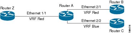
You can assign interfaces and route protocols to a VRF to create virtual Layer 3 networks. An interface exists in only one VRF. The following figure shows one physical network split into two virtual networks with two VRFs. Routers Z, A, and B exist in VRF Red and form one address domain. These routers share route updates that do not include router C because router C is configured in a different VRF.
By default, Cisco NX-OS uses the VRF of the incoming interface to select which routing table to use for a route lookup. You can configure a route policy to modify this behavior and set the VRF that Cisco NX-OS uses for incoming packets.
VRF supports route leaking (import or export) between VRFs. Certain limitations apply to route leaking in VRF-Lite. For more information, see Guidelines and Limitations for VRF Route Leaking.
VRF-Lite
VRF-lite is a feature that enables a service provider to support two or more VPNs, where IP addresses can be overlapped among the VPNs. VRF-lite uses input interfaces to distinguish routes for different VPNs and forms virtual packet-forwarding tables by associating one or more Layer 3 interfaces with each VRF. Interfaces in a VRF can be either physical, such as Ethernet ports, or logical, such as VLAN SVIs, but a Layer 3 interface cannot belong to more than one VRF at any time.
Note | Multiprotocol Label Switching (MPLS) and MPLS control plane are not supported in the VRF-lite implementation. |
Note | VRF-lite interfaces must be Layer 3 interfaces. |
VRF-Aware Services
A fundamental feature of the Cisco NX-OS architecture is that every IP-based feature is VRF aware.
The following VRF-aware services can select a particular VRF to reach a remote server or to filter information based on the selected VRF:
-
AAA—See the Cisco Nexus 9000 Series NX-OS Security Configuration Guide, Release 7.x, for more information.
-
Call Home—See the Cisco Nexus 9000 Series NX-OS System Management Configuration Guide, Release 7.x, for more information.
-
HSRP—See Configuring HSRP for more information.
-
HTTP—See the Cisco Nexus 9000 Series NX-OS Fundamentals Configuration Guide, Release 7.x, for more information.
-
Licensing—See the Cisco NX-OS Licensing Guide for more information.
-
NTP—See the Cisco Nexus 9000 Series NX-OS System Management Configuration Guide, Release 7.x, for more information.
-
RADIUS—See the Cisco Nexus 9000 Series NX-OS Security Configuration Guide, Release 7.x, for more information.
-
Ping and Traceroute —See the Cisco Nexus 9000 Series NX-OS Fundamentals Configuration Guide, Release 7.x, for more information.
-
SSH—See the Cisco Nexus 9000 Series NX-OS Fundamentals Configuration Guide, Release 7.x, for more information.
-
SNMP—See the Cisco Nexus 9000 Series NX-OS System Management Configuration Guide, Release 7.x, for more information.
-
Syslog—See the Cisco Nexus 9000 Series NX-OS System Management Configuration Guide, Release 7.x, for more information.
-
TACACS+—See the Cisco Nexus 9000 Series NX-OS Security Configuration Guide, Release 7.x, for more information.
-
TFTP—See the Cisco Nexus 9000 Series NX-OS Fundamentals Configuration Guide, Release 7.x, for more information.
-
VRRP—See Configuring VRRP for more information.
See the appropriate configuration guide for each service for more information on configuring VRF support in that service.
Reachability
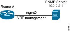
Reachability indicates which VRF contains the routing information necessary to get to the server providing the service. For example, you can configure an SNMP server that is reachable on the management VRF. When you configure that server address on the router, you also configure which VRF that Cisco NX-OS must use to reach the server.
The following figure shows an SNMP server that is reachable over the management VRF. You configure router A to use the management VRF for SNMP server host 192.0.2.1.
Filtering
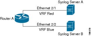
Filtering allows you to limit the type of information that goes to a VRF-aware service based on the VRF. For example, you can configure a syslog server to support a particular VRF. The following figure shows two syslog servers with each server supporting one VRF. syslog server A is configured in VRF Red, so Cisco NX-OS sends only system messages generated in VRF Red to syslog server A.
Combining Reachability and Filtering
You can combine reachability and filtering for VRF-aware services. You configure the VRF that Cisco NX-OS uses to connect to that service as well as the VRF that the service supports. If you configure a service in the default VRF, you can optionally configure the service to support all VRFs.
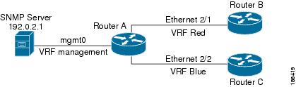
The following figure shows an SNMP server that is reachable on the management VRF. You can configure the SNMP server to support only the SNMP notifications from VRF Red, for example.
Licensing Requirements for VRFs
The following table shows the licensing requirements for this feature:
|
Product |
License Requirement |
|---|---|
|
DCNM |
VRFs require no license. Any feature not included in a license package is bundled with the Cisco DCNM and is provided at no charge to you. For a complete explanation of the DCNM licensing scheme, see the Cisco DCNM Licensing Guide. |
|
Cisco NX-OS |
The default inband and outband management VRFs require no license. Any feature not included in a license package is bundled with the Cisco NX-OS system images and is provided at no extra charge to you. For a complete explanation of the Cisco NX-OS licensing scheme, see the Cisco NX-OS Licensing Guide. |
|
Cisco NX-OS |
VRF-lite requires an Enterprise services license. For a complete explanation of the Cisco NX-OS licensing scheme, see the Cisco NX-OS Licensing Guide. |
Guidelines and Limitations for VRF
VRFs have the following configuration guidelines and limitations in a VRF-lite scenario:
-
When you make an interface a member of an existing VRF, Cisco NX-OS removes all Layer 3 configuration. You should configure all Layer 3 parameters after adding an interface to a VRF.
-
You should add the mgmt0 interface to the management VRF and configure the mgmt0 IP address and other parameters after you add it to the management VRF.
-
If you configure an interface for a VRF before the VRF exists, the interface is operationally down until you create the VRF.
-
Cisco NX-OS creates the default and management VRFs by default. You should make the mgmt0 interface a member of the management VRF.
-
The write erase boot command does not remove the management VRF configuration. You must use the write erase command and then the write erase boot command.
Guidelines and Limitations for VRF-Lite
VRF-lite has the following guidelines and limitations:
-
A switch with VRF-lite has a separate IP routing table for each VRF, which is separate from the global routing table.
-
Because VRF-lite uses different VRF tables, the same IP addresses can be reused. Overlapped IP addresses are allowed in different VPNs.
-
VRF-lite does not support all MPLS-VRF functionality; it does not support label exchange, LDP adjacency, or labeled packets.
-
Multiple virtual Layer 3 interfaces can be connected to a VRF-lite switch.
-
The switch supports configuring a VRF by using physical ports, VLAN SVIs, or a combination of both. The SVIs can be connected through an access port or a trunk port.
-
The Layer 3 TCAM resource is shared between all VRFs. To ensure that any one VRF has sufficient CAM space, use the maximum routes command.
-
The total number of routes supported by all the VRF's is limited by the size of the TCAM.
-
VRF-lite supports BGP, RIP, and static routing.
-
VRF-lite does not support EIGRP.
-
VRF-lite does not affect the packet switching rate.
-
Multicast cannot be configured on the same Layer 3 interface at the same time.
Guidelines and Limitations for VRF Route Leaking
VRF route leaking has the following guidelines and limitations:
-
Route leaking is supported between any two non-default VRFs. It is also supported between the default VRF and any other VRF.
-
Route leaking to the default VRF is not allowed because it is the global VRF.
-
You can restrict route leaking to specific routes using route map filters to match designated IP addresses.
-
By default, the maximum number of IP prefixes that can be leaked is set to 1000 routes. This number can be configured to any value from 0 to 1000.
-
VRF route leaking requires an Enterprise license, and BGP must be enabled.
Default Settings
Table below lists the default settings for VRF parameters.
|
Parameters |
Default |
|---|---|
|
Configured VRFs |
default, management |
|
routing context |
default VRF |
Configuring VRFs
Note | If you are familiar with the Cisco IOS CLI, be aware that the Cisco NX-OS commands for this feature might differ from the Cisco IOS commands that you would use. |
- Creating a VRF
- Assigning VRF Membership to an Interface
- Configuring VRF Parameters for a Routing Protocol
- Configuring a VRF-Aware Service
- Setting the VRF Scope
Creating a VRF
You can create a VRF in a switch.
| Command or Action | Purpose | |
|---|---|---|
| Step 1 | configure terminal Example: switch# configure terminal switch(config)# |
Enters configuration mode. |
| Step 2 | vrf context
name Example: switch(config)# vrf definition Enterprise switch(config-vrf)# |
Creates a new VRF and enters VRF configuration mode. The name can be any case-sensitive, alphanumeric string up to 32 characters. |
| Step 3 | ip route { ip-prefix | ip-addr ip-mask } {[ next-hop | nh-prefix ] | [ interface next-hop | nh-prefix ]} [ tag
tag-value [ pref ] Example: switch(config-vrf)# ip route 192.0.2.0/8 ethernet 1/2 192.0.2.4 |
Configures a static route and the interface for this static route. You can optionally configure the next-hop address. The preference value sets the administrative distance. The range is from 1 to 255. The default is 1. |
| Step 4 | show vrf [ vrf-name ] Example: switch(config-vrf)# show vrf Enterprise | (Optional)
Displays VRF information. |
| Step 5 | copy running-config startup-config Example: switch(config)# copy running-config startup-config | (Optional)
Saves this configuration change. |
Use the no vrf context command to delete the VRF and the associated configuration:
|
Command |
Purpose |
|---|---|
|
no vrf context name
Example: switch(config)# no vrf context Enterprise |
Deletes the VRF and all associated configuration. |
Any commands available in global configuration mode are also available in VRF configuration mode.
This example shows how to create a VRF and add a static route to the VRF:
switch# configure terminal switch(config)# vrf context Enterprise switch(config-vrf)# ip route 192.0.2.0/8 ethernet 1/2 switch(config-vrf)# exit switch(config)# copy running-config startup-config
Assigning VRF Membership to an Interface
You can make an interface a member of a VRF.
Assign the IP address for an interface after you have configured the interface for a VRF.
| Command or Action | Purpose | |
|---|---|---|
| Step 1 | configure terminal Example: switch# configure terminal switch(config)# |
Enters configuration mode. |
| Step 2 | interface
interface-type slot/port Example: switch(config)# interface ethernet 1/2 switch(config-if)# |
Enters interface configuration mode. |
| Step 3 | vrf member
vrf-name Example: switch(config-if)# vrf member RemoteOfficeVRF |
Adds this interface to a VRF. |
| Step 4 | ip address
ip-prefix/length Example: switch(config-if)# ip address 192.0.2.1/16 |
Configures an IP address for this interface. You must do this step after you assign this interface to a VRF. |
| Step 5 | show vrf
vrf-name
interface
interface-type number Example: switch(config-vrf)# show vrf Enterprise interface ethernet 1/2 |
Displays VRF information. |
| Step 6 | copy running-config startup-config Example: switch(config)# copy running-config startup-config | (Optional)
Saves this configuration change. |
This example shows how to add an interface to the VRF:
switch# configure terminal switch(config)# interface ethernet 1/2 switch(config-if)# vrf member RemoteOfficeVRF switch(config-if)# ip address 192.0.2.1/16 switch(config-if)# copy running-config startup-config
Configuring VRF Parameters for a Routing Protocol
You can associate a routing protocol with one or more VRFs. See the appropriate chapter for information on how to configure VRFs for the routing protocol. This section uses OSPFv2 as an example protocol for the detailed configuration steps.
| Command or Action | Purpose | |
|---|---|---|
| Step 1 | configure terminal Example: switch# configure terminal switch(config)# |
Enters configuration mode. |
| Step 2 | router ospf
instance-tag Example: switch(config-vrf)# router ospf 201 switch(config-router)# |
Creates a new OSPFv2 instance with the configured instance tag. |
| Step 3 | vrf
vrf-name Example: switch(config-router)# vrf RemoteOfficeVRF switch(config-router-vrf)# |
Enters VRF configuration mode. |
| Step 4 | maximum-paths
paths Example: switch(config-router-vrf)# maximum-paths 4 | (Optional)
Configures the maximum number of equal OSPFv2 paths to a destination in the route table for this VRF. Used for load balancing. |
| Step 5 | interface
interface-typeslot/port Example: switch(config)# interface ethernet 1/2 switch(config-if)# |
Enters interface configuration mode. |
| Step 6 | vrf member
vrf-name Example: switch(config-if)# vrf member RemoteOfficeVRF |
Adds this interface to a VRF. |
| Step 7 | ip address
ip-prefix/length Example: switch(config-if)# ip address 192.0.2.1/16 |
Configures an IP address for this interface. You must do this step after you assign this interface to a VRF. |
| Step 8 | ip router ospf
instance-tag
area
area-id Example: switch(config-if)# ip router ospf 201 area 0 |
Assigns this interface to the OSPFv2 instance and area configured. |
| Step 9 | copy running-config startup-config Example: switch(config)# copy running-config startup-config | (Optional)
Saves this configuration change. |
This example shows how to create a VRF and add an interface to the VRF:
switch# configure terminal switch(config)# vrf context RemoteOfficeVRF switch(config-vrf)# exit switch(config)# router ospf 201 switch(config-router)# vrf RemoteOfficeVRF switch(config-router-vrf)# maximum-paths 4 switch(config-router-vrf)# interface ethernet 1/2 switch(config-if)# vrf member RemoteOfficeVRF switch(config-if)# ip address 192.0.2.1/16 switch(config-if)# ip router ospf 201 area 0 switch(config-if)# exit switch(config)# copy running-config startup-config
Configuring a VRF-Aware Service
You can configure a VRF-aware service for reachability and filtering. See the VRF-Aware Services section for links to the appropriate chapter or configuration guide for information on how to configure the service for VRFs. This section uses SNMP and IP domain lists as example services for the detailed configuration steps.
| Command or Action | Purpose | |
|---|---|---|
| Step 1 | configure terminal Example: switch# configure terminal switch(config)# |
Enters configuration mode. |
| Step 2 | snmp-server host
ip-address [ filter_vrf
vrf-name ] [ use-vrf
vrf-name ] Example: switch(config)# snmp-server host 192.0.2.1 use-vrf Red switch(config-vrf)# |
Configures a global SNMP server and configures the VRF that Cisco NX-OS uses to reach the service. Use the filter-vrf keyword to filter information from the selected VRF to this server. |
| Step 3 | vrf context
vrf-name Example: switch(config)# vrf context Blue switch(config-vrf)# |
Creates a new VRF. |
| Step 4 | ip domain-list
domain-name [ all-vrfs ][ use-vrf
vrf-name ] Example: switch(config-vrf)# ip domain-list List all-vrfs use-vrf Blue switch(config-vrf)# |
Configures the domain list in the VRF and optionally configures the VRF that Cisco NX-OS uses to reach the domain name listed. |
| Step 5 | copy running-config startup-config Example: switch(config)# copy running-config startup-config | (Optional)
Saves this configuration change. |
This example shows how to send SNMP information for all VRFs to SNMP host 192.0.2.1, reachable on VRF Red:
switch# configure terminal switch(config)# snmp-server host 192.0.2.1 for-all-vrfs use-vrf Red switch(config)# copy running-config startup-config
This example shows how to Filter SNMP information for VRF Blue to SNMP host 192.0.2.12, reachable on VRF Red:
switch# configure terminal
switch(config)# vrf definition Blue
switch(config-vrf)# snmp-server host 192.0.2.12 use-vrf Red
switch(config)# copy running-config startup-config
Setting the VRF Scope
You can set the VRF scope for all EXEC commands (for example, show commands). This automatically restricts the scope of the output of EXEC commands to the configured VRF. You can override this scope by using the VRF keywords available for some EXEC commands.
To set the VRF scope, use the following command in EXEC mode:
|
Command |
Purpose |
|---|---|
|
routing-context vrf vrf-name
Example: switch# routing-context vrf red switch%red# |
Sets the routing context for all EXEC commands. Default routing context is the default VRF. |
To return to the default VRF scope, use the following command in EXEC mode:
|
Command |
Purpose |
|---|---|
|
routing-context vrf default Example: switch%red# routing-context vrf default switch# |
Sets the default routing context. |
Verifying the VRF Configuration
To display the VRF configuration information, perform one of the following tasks:
|
Command |
Purpose |
|---|---|
|
show vrf [vrf-name] |
Displays the information for all or one VRF. |
| show vrf [vrf-name] detail |
Displays detailed information for all or one VRF. |
|
show vrf [vrf-name] [interface interface-type slot/port] |
Displays the VRF status for an interface. |
Configuration Examples for VRF
This example shows how to configure VRF Red, add an SNMP server to that VRF, and add an instance of OSPF to VRF Red:
configure terminal
vrf context Red
snmp-server host 192.0.2.12 use-vrf Red
router ospf 201
interface ethernet 1/2
vrf member Red
ip address 192.0.2.1/16
ip router ospf 201 area 0
This example shows how to configure VRF Red and Blue, add an instance of OSPF to each VRF, and create an SNMP context for each OSPF instance in each VRF:
configure terminal
!Create the VRFs
vrf context Red
vrf context Blue
!Create the OSPF instances and associate them with each VRF
feature ospf
router ospf Lab
vrf Red
router ospf Production
vrf Blue
!Configure one interface to use ospf Lab on VRF Red
interface ethernet 1/2
vrf member Red
ip address 192.0.2.1/16
ip router ospf Lab area 0
no shutdown
!Configure another interface to use ospf Production on VRF Blue
interface ethernet 10/2
vrf member Blue
ip address 192.0.2.1/16
ip router ospf Production area 0
no shutdown
!configure the SNMP server
snmp-server user admin network-admin auth md5 nbv-12345
snmp-server community public ro
!Create the SNMP contexts for each VRF
snmp-server context lab instance Lab vrf Red
snmp-server context production instance Production vrf Blue
Use the SNMP context lab to access the OSPF-MIB values for the OSPF instance Lab in VRF Red in the previous example.
This example shows how to configure route leaking between two non-default VRF's, and from the default VRF to a non-default VRF:
feature bgp
vrf context Green
ip route 33.33.33.33/32 35.35.1.254
address-family ipv4 unicast
route-target import 3:3
route-target export 2:2
export map test
import map test
import vrf default map test
interface Ethernet1/7
vrf member Green
ip address 35.35.1.2/24
vrf context Shared
ip route 44.44.44.44/32 45.45.1.254
address-family ipv4 unicast
route-target import 1:1
route-target import 2:2
route-target export 3:3
export map test
import map test
import vrf default map test
interface Ethernet1/11
vrf member Shared
ip address 45.45.1.2/24
router bgp 100
address-family ipv4 unicast
redistribute static route-map test
vrf Green
address-family ipv4 unicast
redistribute static route-map test
vrf Shared
address-family ipv4 unicast
redistribute static route-map test
ip prefix-list test seq 5 permit 0.0.0.0/0 le 32
route-map test permit 10
match ip address prefix-list test
ip route 100.100.100.100/32 55.55.55.1
nexus# show ip route vrf all
IP Route Table for VRF "default"
'*' denotes best ucast next-hop
'**' denotes best mcast next-hop
'[x/y]' denotes [preference/metric]

'%<string>' in via output denotes VRF <string>
55.55.55.0/24, ubest/mbest: 1/0, attached
*via 55.55.55.5, Lo0, [0/0], 00:07:59, direct
55.55.55.5/32, ubest/mbest: 1/0, attached
*via 55.55.55.5, Lo0, [0/0], 00:07:59, local
100.100.100.100/32, ubest/mbest: 1/0
*via 55.55.55.1, [1/0], 00:07:42, static
IP Route Table for VRF "management"
'*' denotes best ucast next-hop
'**' denotes best mcast next-hop
'[x/y]' denotes [preference/metric]
'%<string>' in via output denotes VRF <string>
0.0.0.0/0, ubest/mbest: 1/0
*via 10.29.176.1, [1/0], 12:53:54, static
10.29.176.0/24, ubest/mbest: 1/0, attached
*via 10.29.176.233, mgmt0, [0/0], 13:11:57, direct
10.29.176.233/32, ubest/mbest: 1/0, attached
*via 10.29.176.233, mgmt0, [0/0], 13:11:57, local
IP Route Table for VRF "Green"
'*' denotes best ucast next-hop
'**' denotes best mcast next-hop
'[x/y]' denotes [preference/metric]
'%<string>' in via output denotes VRF <string>
33.33.33.33/32, ubest/mbest: 1/0
*via 35.35.1.254, [1/0], 00:23:44, static
35.35.1.0/24, ubest/mbest: 1/0, attached
*via 35.35.1.2, Eth1/7, [0/0], 00:26:46, direct
35.35.1.2/32, ubest/mbest: 1/0, attached
*via 35.35.1.2, Eth1/7, [0/0], 00:26:46, local
44.44.44.44/32, ubest/mbest: 1/0
*via 45.45.1.254%Shared, [20/0], 00:12:08, bgp-100, external, tag 100
100.100.100.100/32, ubest/mbest: 1/0
*via 55.55.55.1%default, [20/0], 00:07:41, bgp-100, external, tag 100
IP Route Table for VRF "Shared"
'*' denotes best ucast next-hop
'**' denotes best mcast next-hop
'[x/y]' denotes [preference/metric]
'%<string>' in via output denotes VRF <string>
33.33.33.33/32, ubest/mbest: 1/0
*via 35.35.1.254%Green, [20/0], 00:12:34, bgp-100, external, tag 100
44.44.44.44/32, ubest/mbest: 1/0
*via 45.45.1.254, [1/0], 00:23:16, static
45.45.1.0/24, ubest/mbest: 1/0, attached
*via 45.45.1.2, Eth1/11, [0/0], 00:25:53, direct
45.45.1.2/32, ubest/mbest: 1/0, attached
*via 45.45.1.2, Eth1/11, [0/0], 00:25:53, local
100.100.100.100/32, ubest/mbest: 1/0
*via 55.55.55.1%default, [20/0], 00:07:41, bgp-100, external, tag 100
nexus(config)#
Related Topics
The following topics can give more information on VRFs:
Additional References
For additional information related to implementing virtualization, see the following sections:
Related Documents
|
Related Topic |
Document Title |
|---|---|
|
VRF CLI |
Standards
|
Standards |
Title |
|---|---|
|
No new or modified standards are supported by this feature, and support for existing standards has not been modified by this feature. |
— |
Feature History for VRF
Table below lists the release history for this feature.
|
Feature Name |
Releases |
Feature Information |
|---|---|---|
|
VRF |
5.0(3)A1(1) |
This feature was introduced. |
|
VRF Route Leaking |
6.0(2)A1(1) |
This feature was introduced. |
 Feedback