- New and Changed Information
- Preface
- Fabric Overview
- Configuring and Managing VSANs
- Configuring SAN Device Virtualization
- Creating Dynamic VSANs
- Configuring and Managing Zones
- Distributing Device Alias Services
- Configuring FCoE
- Configuring Fibre Channel Routing Services and Protocols
- Configuring Dense Wavelength Division Multiplexing
- Managing FLOGI, Name Server, FDMI, and RSCN Databases
- Discovering SCSI Targets
- Configuring FICON
- Configuring Advanced Fabric Features
- Index
Fabric Configuration Guide, Cisco DCNM for SAN, Release 6.x
Bias-Free Language
The documentation set for this product strives to use bias-free language. For the purposes of this documentation set, bias-free is defined as language that does not imply discrimination based on age, disability, gender, racial identity, ethnic identity, sexual orientation, socioeconomic status, and intersectionality. Exceptions may be present in the documentation due to language that is hardcoded in the user interfaces of the product software, language used based on RFP documentation, or language that is used by a referenced third-party product. Learn more about how Cisco is using Inclusive Language.
- Updated:
- June 20, 2012
Chapter: Configuring SAN Device Virtualization
Configuring SAN Device Virtualization
This chapter describes how to configure virtual devices to represent physical end devices for switches running Cisco MDS SAN-OS Release 3.1(2) and later, or NX-OS Release 4.1(1a) and later.
Cisco SAN device virtualization (SDV) is a licensed feature included in the Cisco MDS 9000 Family Enterprise package (ENTERPRISE_PKG). Refer to the Cisco NX-OS Family Licensing Guide for details about acquiring licenses.
Information About SDV
As of Cisco SAN-OS Release 3.1(2) and later, you can use Cisco SAN device virtualization to create virtual devices that represent physical end-devices. Virtualization of SAN devices accelerates swapout or failover to a replacement disk array, and it also minimizes downtime when replacing host bus adapters (HBAs) or when rehosting an application on a different server.
SAN device virtualization enables you to:
- Reduce the amount of time it takes for data migration, and ultimately the overall amount of downtime.
- Improve ease-of-use and reduce the possibility of user-introduced errors during the failover by performing the operation in a single step.
- Easily scale to larger numbers of targets.
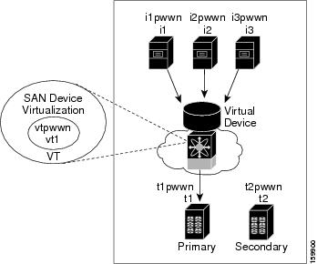
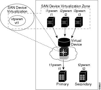
SAN devices that are virtualized can be either initiators or targets. You can virtualize targets to create a virtual target and also virtualize initiators to create a virtual initiator. SAN device configurations do not distinguish between virtual initiators and virtual targets (see Figure 1-1 and Figure 1-2).
Figure 1-1 Target Virtualization
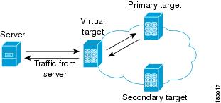
Figure 1-2 Initiator Virtualization
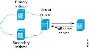

Note![]() While most of the examples in this chapter describe target virtualization, the initiator virtualization functions similarly.
While most of the examples in this chapter describe target virtualization, the initiator virtualization functions similarly.
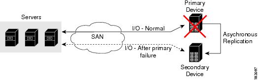
Typically, today’s deployments for handling device failures are designed for high availability (HA), with redundancy being a key part of this design. Consider the situation where a target is designed to be redundant. Two arrays are deployed–a primary and secondary in this situation. Enterprises often use some type of consistency technology (such as EMF SRDF) between the primary and secondary arrays to ensure that the secondary is a mirrored copy of the production LUN. However, if the primary array fails, it must be replaced by the secondary because all I/O must occur on the secondary array. Problems can occur because the time required to bring the secondary array up and have it working often takes longer than most can afford (Figure 1-3 illustrates this dilemma).
Figure 1-3 Typical Deployment for Handling Device Failures Before SDV
If a storage array is replaced without using Cisco SDV, then it may require the following actions:
- Taking down a server to modify zoning and account for the new array.
- Changing the Cisco NX-OS configuration to accommodate Fibre Channel IDs (FC IDs) and pWWNs of the new array.
- Changing a server configuration to accommodate the new FC IDs and pWWNs.
More specifically, without SDV you might experience the following conditions:
- It can take a considerable amount of time to configure a secondary device for a typical production environment.
- In the zoning configuration, all the initiators must be rezoned with the secondary device, and certain initiators must also be reconfigured. For example, the WWN and FC ID of the secondary device are different, so driver files must be changed and the server must be rebooted.
- Clustering (multiple initiators) compounds the problem, and the failover procedure must be repeated for each server of the cluster. Think of a server cluster as a set of HBAs–any storage array FC ID changes must be performed for each HBA.
SDV enables you to achieve the following performance targets:
- Reduce the amount of time it takes for data migration, and ultimately the overall amount of downtime.
- Easily scale to larger numbers of devices.
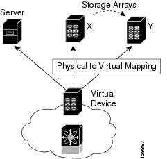
Figure 1-4 illustrates the benefits of SDV. In this configuration, disk array Y replaces disk array X. When disk array X was deployed, the user created virtual devices for all the Fibre Channel interfaces using SDV. After data replication from disk array X was completed, the user briefly pauses activity on the application server and relinked disk array Y to the virtual devices used by the server, completing the swapout of disk array X. No zoning changes or host operating system configuration changes were required during the time-critical period when the swap was performed; this significantly minimized application downtime.
Note![]() The array administrator will likely have to perform actions on array Y for it to become a primary device and accept server logins before linking the virtual device to the array Y pWWN.
The array administrator will likely have to perform actions on array Y for it to become a primary device and accept server logins before linking the virtual device to the array Y pWWN.
This section includes the following topics:
Key Concepts
The following terms are used throughout this chapter:
- Virtual device—The virtualized or proxy representation of the real device, which is registered with the name server and has a pWWN and FC ID. A virtual device exists as long as its real (physical) counterpart is online. The virtual device pWWN and FC ID must be unique and cannot clash with any real device pWWNs and FC IDs.
- Virtual domain—Reserved by SDV to assign FC IDs to virtual devices. If the switch that reserved the domain goes down, another switch takes over its role using the same domain.
- Primary device—The device that is configured as primary. By default, the primary device becomes the active device if it is online.
- Secondary device—The additional device that is configured. By default, the secondary device is standby.
- Active device—The device that is currently virtualized is called the active device. By default, the primary device becomes the active device if it is online. The active device is indicated by a (*) symbol.
Automatic Failover and Fallback
As of Cisco MDS NX-OS Release 4.1(1a), SAN device virtualization supports automatic failover and fallback configurations for the virtual devices. In all of the earlier releases, when there was a failure, you needed to manually configure the device as primary to make it active. With the introduction of automatic failover and fallback configurations, the active device is distinguished from the primary device indicated by a (*) symbol.
- Auto failover—When there is a failure, the failover auto attribute automatically shuts down the primary device and brings up the secondary device to active state. When the primary device comes back online, it requires user intervention to switchover.
- Auto failover with fallback—In addition to automatic failover, when the primary device comes back online after a failover, the primary device is brought to active state and the secondary device moved to standby state.
Resolving Fabric Merge Conflicts
Whenever two fabrics merge, SDV merges its database. A merge conflict can occur when there is a run-time information conflict or configuration mismatch. Run-time conflicts can occur due to:
- Identical pWWNs have been assigned to different virtual devices.
- The same virtual devices are assigned different pWWNs.
- The virtual device and virtual FC ID are mismatched.
A blank commit is a commit operation that does not contain configuration changes, and enforces the SDV configuration of the committing switch fabric-wide. A blank commit operation resolves merge conflicts by pushing the configuration from the committing switch throughout the fabric, which reinitializes the conflicting virtual devices. Exercise caution while performing this operation, as it can easily take some virtual devices offline.
Merge failures resulting from a pWWN conflict can cause a failure with the device alias as well. A blank commit operation on a merge-failed VSAN within SDV should resolve the merge failure in the device alias.
You can avoid merge conflicts due to configuration mismatch by ensuring that:
Licensing Requirements for SAN Device Virtualization
The following table shows the licensing requirements for this feature:
|
|
|
|---|---|
The enterprise license is required for SAN device virtualization. For a complete explanation of the licensing scheme, see the Cisco MDS 9000 Family NX-OS Licensing Guide. |
Guidelines and Limitations
As of MDS NX-OS Release 4.1(1a), the following conditions must be considered when configuring the virtual device failover attributes:
- The attribute configuration is supported only with MDS NX-OS Release 4.1(1a) and later. In a mixed mode fabric where earlier releases are combined, the attribute configuration will fail.
- When the failover attribute is configured, if the primary device is offline then the secondary device becomes active.
- When the failover attribute is deleted after the primary device failover to the secondary device, then the primary becomes active if the primary device is online. If the primary device is not online, then the SDV virtual device is shut down.
Note![]() The SDV attributes configuration is supported in Cisco DCNM for SAN Release 4.1(2) and later.
The SDV attributes configuration is supported in Cisco DCNM for SAN Release 4.1(2) and later.
This section includes the guidelines and limitations for this feature:
- SDV Requirements and Guidelines
- Guidelines for Downgrading SDV
- Downgrading with Attributes Configured
- Downgrading with Virtual Initiators Configured
- Downgrading with SDV LUN Zoning Configured
SDV Requirements and Guidelines
Be aware of the following requirements and guidelines as you plan and configure SDV:
- SDV should be enabled on switches where devices that are part of SDV zones are connected.
- SDV does not work for devices connected to non-MDS switches.
- Broadcast zoning is not supported for a zone with a virtual device.
- IVR and SDV cannot be used for the same device. A SDV-virtualized device cannot be part of an IVR zone or zoneset.
- Virtual device names should be unique across VSANs because they are registered with the device alias server, which is unaware of VSANs. For example, if you have enabled SDV and have registered a name, vt1 in both VSAN 1 and VSAN 2, then the device alias server cannot store both entries because they have the same name.
- You cannot specify the same primary device for different virtual devices.
- SDV does not work with soft zoning ( Soft zoning means that zoning restrictions are applied only during interaction between the name server and the end device). If an end device somehow knows the FC ID of a device outside its zone, it can access that device; it does not work with the zone default-zone permit vsan operation (which would otherwise permit or deny traffic to members in the default zone).
- If devices are not already zoned with the initiators, then you can configure SDV virtual device zones with no negative impact. If they are already zoned, then zoning changes are required.
- The real device-virtual device zone cannot coexist with the real device-real device zone. If the real devices are not already zoned together, then you can configure the real device-virtual device zone with no negative impact. If these devices are already zoned, then adding the real device-virtual device zone may cause the zone activation to fail. If this occurs, then you must delete one of the zones before activation.
For example, a user attempts to create a configuration with zone A, which consists of I, the initiator, and T, the target (I,T), and zone B, which consists of a virtual initiator, VI, and real target, T (zone VI, T). Such a configuration would fail. Likewise, an attempt to configure zone C, which consists of an initiator, I, and target T, with zone D, which consists of an initiator, I, and virtual target, VT (zone I, VT), would also fail.

Guidelines for Downgrading SDV
As of MDS NX-OS Release 4.1(1a), SDV supports failover and fallback attribute configuration. Downgrading to an earlier release requires you to remove the attribute configurations before downgrading.
As of SAN-OS Release 3.1(3), SDV supports virtual initiators and LUN zoning. Consequently, in SAN-OS Releases 3.1(3) and later, if virtual initiators are configured or SDV devices are configured as LUN-based members of a zone, a configuration check will indicate that downgrading to SAN-OS Release 3.1(2) may be disruptive and is therefore not recommended.
Downgrading with Attributes Configured
As of MDS NX-OS Release 4.1(1a), SDV supports failover and fallback attribute configuration. To successfully downgrade to an earlier release, you must remove the attribute configurations before downgrading.
Downgrading with Virtual Initiators Configured
If SDV virtual initiators are configured, you will be unable to downgrade to SAN-OS Release 3.1(2).
This incompatibility only warns before a downgrade. We recommend that you remove the virtual initiator configuration or shut down the initiator port so that there are no inconsistencies in the downgraded version.
Downgrading with SDV LUN Zoning Configured
The following are downgrade scenarios when SDV LUN zoning is configured:
- Real initiator and SDV virtual target with LUN
- SDV virtual initiator and real target with LUN
- SDV virtual initiator and SDV virtual target with LUN
In each of these cases, a configuration check is registered to prevent users from downgrading to SAN-OS Release 3.1(2). This incompatibility will be disruptive if you proceed with the downgrade.
To avoid the configuration check, delete all the LUN zone members from SDV zones, and then activate the zone set before the downgrade.
Default Settings
Table 1-1 lists the default settings for SDV parameters.
|
|
|
|---|---|
Configuring SDV
SDV is a distributed service and uses Cisco Fabric Services (CFS) distribution to synchronize the databases. When you configure SDV, it starts a CFS session and locks the fabric. When a fabric is locked, Cisco NX-OS software does not allow any configuration changes from a switch other than the switch holding the lock and issues a message to inform users about the locked status. Configuration changes are held in a pending database for the application. You must perform a commit operation to make the configuration active and to release the lock for all switches.
Refer to the Cisco MDS 9000 Family NX-OS System Management Configuration Guide for more details about CFS.
Note![]() When you enable SDV, CFS distribution is also enabled; CFS distribution cannot be disabled for SDV.
When you enable SDV, CFS distribution is also enabled; CFS distribution cannot be disabled for SDV.
This section includes the following topics:
- Configuring a Virtual Device
- Configuring a Zone for a Virtual Device
- Linking a Virtual Device with a Physical Device
- Discarding Changes
- Clearing SDV Changes
Configuring a Virtual Device
A virtual device is identified by an alphanumeric name of up to 32 characters and defines all the real devices (one primary and one or more secondary) that it represents. Upon the successful creation of a virtual device, the virtual device name is internally registered as the device alias name with the device alias database; the pWWN is automatically assigned by the system using Cisco Organizational Unique Identifier (OUI). A virtual device appears as a real, physical device. You can enumerate up to 128 devices for a virtual device. There is a limit of 4095 on the number of virtual devices that you can create in a single VSAN.
Note![]() As of Cisco MDS SAN-OS Release 3.1(2) and NX-OS Release 4.1(1a), SDV supports up to 1024 virtual devices per VSAN.
As of Cisco MDS SAN-OS Release 3.1(2) and NX-OS Release 4.1(1a), SDV supports up to 1024 virtual devices per VSAN.
Detailed Steps
To configure a virtual target and commit it to the fabric configuration, follow these steps:
Step 1![]() Expand SAN in the Logical Domains pane, and then expand the fabric in which your VSAN resides.
Expand SAN in the Logical Domains pane, and then expand the fabric in which your VSAN resides.
Step 2![]() Expand the VSAN in which you want to create the virtual target and select SDV. You see the switches in the VSAN that you selected listed in the Information pane.
Expand the VSAN in which you want to create the virtual target and select SDV. You see the switches in the VSAN that you selected listed in the Information pane.
Step 3![]() In the Control tab, select enable from the drop-down menu in the Command column to enable SAN device virtualization for a particular switch in the VSAN.
In the Control tab, select enable from the drop-down menu in the Command column to enable SAN device virtualization for a particular switch in the VSAN.
Step 4![]() Click the Apply Changes icon to commit the configuration change.
Click the Apply Changes icon to commit the configuration change.
Step 5![]() Click the CFS tab. Confirm that the SAN device virtualization feature is enabled for the switch.
Click the CFS tab. Confirm that the SAN device virtualization feature is enabled for the switch.
Step 6![]() Click the Virtual Devices tab and then click the Create Row icon.
Click the Virtual Devices tab and then click the Create Row icon.
You see the Create Virtual Devices dialog box.
Step 7![]() Select the Virtual Device ID from the drop-down list (ranges from 1 to 4096).
Select the Virtual Device ID from the drop-down list (ranges from 1 to 4096).
Step 8![]() Enter a Name for the Virtual Device. Select the Virtual Domain and enter a Virtual FC ID for the virtual target.
Enter a Name for the Virtual Device. Select the Virtual Domain and enter a Virtual FC ID for the virtual target.
Step 9![]() Check only the autoFailover check box or check the autoFailover and primFallback check boxes. For more information, see the “Automatic Failover and Fallback” section. You can also change the option in the Option column of the Virtual Devices tab.
Check only the autoFailover check box or check the autoFailover and primFallback check boxes. For more information, see the “Automatic Failover and Fallback” section. You can also change the option in the Option column of the Virtual Devices tab.
Step 10![]() Click Create to create the virtual target.
Click Create to create the virtual target.
Step 11![]() Click the CFS icon to commit and distribute the configuration changes.
Click the CFS icon to commit and distribute the configuration changes.
Examples
Figure 1-5 shows a configuration that includes a new virtual device, vt1.
Figure 1-5 Creating a Virtual Device
The pWWN of the virtual target does not appear in the zoning end devices database in DCNM-SAN. If you want to zone the virtual device with a pWWN, you must enter it in the Add Member to Zone dialog box when creating a zone. However, if the device alias is in enhanced mode, the virtual device names appear in the device alias database in the DCNM-SAN zoning window. In this case, users can choose to select either the device alias name or enter the pWWN in the Add Member to Zone dialog box.
For more information, see the “Adding Zone Members” section.
Configuring a Zone for a Virtual Device
After configuring a virtual device, you must create a zone that includes all the other real devices and the virtual device as members, and add this zone to a zone set, which you can activate. You can add the virtual device to the zone using the configured name and member type as the device alias.
Note![]() This configuration process does not support interoperability. If you are working in interop-VSANs, we recommend that you configure the zone directly using the system-assigned pWWN of the virtual device.
This configuration process does not support interoperability. If you are working in interop-VSANs, we recommend that you configure the zone directly using the system-assigned pWWN of the virtual device.
Set the device alias mode to enhanced when using SDV (because the pWWN of a virtual device could change).
Examples
Figure 1-6 shows a virtual device-name device alias (vt1) zoned with the real devices activated; the primary device is online.
Figure 1-6 Zoning the Virtual Device with Real Devices
SDV is enabled on a switch and a virtual device is defined. SDV assigns a pWWN for the virtual device, and it is zoned based on the pWWN in a zone. If you later disable SDV, this configuration is lost. If you reenable SDV and create the virtual device using the same name, there is no guarantee that it will get the same pWWN again. You would have to rezone the pWWN-based zone. However, if you perform zoning based on the device-alias name, there are no configuration changes required if or when the pWWN changes.
Be sure you understand how device alias modes work before enabling them. Refer to Chapter 1, “Distributing Device Alias Services” for details and requirements about device alias modes.
Linking a Virtual Device with a Physical Device
After creating a virtual device and configuring it as part of a zone, you can define the primary device for it using the link command, which is also used to fail over to the secondary device.
Note![]() When a link operation fails over to the secondary device, the virtual device is taken offline, and then brought online.
When a link operation fails over to the secondary device, the virtual device is taken offline, and then brought online.
Prerequisites
As of MDS NX-OS Release 4.1(1a), the following conditions must be considered before linking a device:
- If you link to the secondary device which is currently active because of failover, the primary tag is moved to the secondary device and the secondary device becomes the primary device.
- When the secondary device is active, if you link to a third device, and if the fallback attribute was not configured, the third device becomes the primary device but the secondary device continues to be the active device.
- When the secondary device is active, if you link to a third device, and if the fallback attribute was configured, then the third device becomes the primary device as well as the active device.
Detailed Steps
To link a virtual target with a physical target, follow these steps:
Step 1![]() Click the Real Devices tab and then click the Create Row icon.
Click the Real Devices tab and then click the Create Row icon.
Step 2![]() Select the Virtual Device ID from the pull-down list or enter an existing ID for the virtual target that you are linking with a physical target.
Select the Virtual Device ID from the pull-down list or enter an existing ID for the virtual target that you are linking with a physical target.
Step 3![]() Select the Real Device ID of the physical target that you are linking with the virtual target.
Select the Real Device ID of the physical target that you are linking with the virtual target.
Step 4![]() Click either the pWWN or deviceAlias radio button, and select the appropriate pWWN or device alias from the pull-down menu. The Name field is automatically populated when you select the pWWN or device alias.
Click either the pWWN or deviceAlias radio button, and select the appropriate pWWN or device alias from the pull-down menu. The Name field is automatically populated when you select the pWWN or device alias.
Step 5![]() Click either the primary or secondary radio button for the Map Type.
Click either the primary or secondary radio button for the Map Type.
Step 6![]() Click the CFS icon to save and distribute these changes, or click Close to discard any unsaved changes.
Click the CFS icon to save and distribute these changes, or click Close to discard any unsaved changes.
Discarding Changes
At any time, you can discard the uncommitted changes to the running configuration and release the fabric lock (prior to entering the sdv commit command). If you discard the pending changes, the configuration remains unaffected and the lock is released.
Clearing SDV Changes
If you have performed a SDV task and have forgotten to release the lock by either committing or discarding the changes, an administrator can release the lock from any switch in the fabric. If the administrator performs this task, your changes to the pending database are discarded and the fabric lock is released.

Tip![]() The pending database is only available in the volatile directory and is subject to being discarded if the switch is restarted.
The pending database is only available in the volatile directory and is subject to being discarded if the switch is restarted.
Field Descriptions for SDV
This section displays the field descriptions for this feature.
SDV Virtual Devices
SDV Real Devices
Additional References
For additional information related to implementing VSANs, see the following section:
Related Document
|
|
|
|---|---|
Standards
|
|
|
|---|---|
No new or modified standards are supported by this feature, and support for existing standards has not been modified by this feature. |
RFCs
|
|
|
|---|---|
No new or modified RFCs are supported by this feature, and support for existing RFCs has not been modified. |
MIBs
|
|
|
|---|---|
To locate and download MIBs, go to the following URL: http://www.cisco.com/en/US/products/ps5989/prod_technical_reference_list.html |
 Feedback