- New and Changed Information
- Preface
- Fabric Overview
- Configuring and Managing VSANs
- Configuring SAN Device Virtualization
- Creating Dynamic VSANs
- Configuring and Managing Zones
- Distributing Device Alias Services
- Configuring FCoE
- Configuring Fibre Channel Routing Services and Protocols
- Configuring Dense Wavelength Division Multiplexing
- Managing FLOGI, Name Server, FDMI, and RSCN Databases
- Discovering SCSI Targets
- Configuring FICON
- Configuring Advanced Fabric Features
- Index
Fabric Configuration Guide, Cisco DCNM for SAN, Release 6.x
Bias-Free Language
The documentation set for this product strives to use bias-free language. For the purposes of this documentation set, bias-free is defined as language that does not imply discrimination based on age, disability, gender, racial identity, ethnic identity, sexual orientation, socioeconomic status, and intersectionality. Exceptions may be present in the documentation due to language that is hardcoded in the user interfaces of the product software, language used based on RFP documentation, or language that is used by a referenced third-party product. Learn more about how Cisco is using Inclusive Language.
- Updated:
- June 20, 2012
Chapter: Configuring and Managing VSANs
- Information About VSANs
- VSANs Topologies
- VSAN Advantages
- VSANs Versus Zones
- VSAN Configuration
- About VSAN Creation
- About Port VSAN Membership
- About the Default VSAN
- About the Isolated VSAN
- Operational State of a VSAN
- About Static VSAN Deletion
- About Load Balancing
- About Interop Mode
- About FICON VSANs
- Host Provisioning Wizard
- Licensing Requirements for VSAN
- Default Settings
- Configuring VSANs
- Configuring Load Balancing
- Verifying VSAN Configuration
- Field Descriptions for VSAN
- Additional References
Configuring and Managing VSANs
You can achieve higher security and greater stability in Fibre Channel fabrics by using virtual SANs (VSANs) on Cisco MDS 9000 Family switches and Cisco Nexus 5000 Series switches. VSANs provide isolation among devices that are physically connected to the same fabric. With VSANs you can create multiple logical SANs over a common physical infrastructure. Each VSAN can contain up to 239 switches and has an independent address space that allows identical Fibre Channel IDs (FC IDs) to be used simultaneously in different VSANs. This chapter includes the following sections:
Information About VSANs
A VSAN is a virtual storage area network (SAN). A SAN is a dedicated network that interconnects hosts and storage devices primarily to exchange SCSI traffic. In SANs, you use the physical links to make these interconnections. A set of protocols run over the SAN to handle routing, naming, and zoning. You can design multiple SANs with different topologies.
With the introduction of VSANs, the network administrator can build a single topology containing switches, links, and one or more VSANs. Each VSAN in this topology has the same behavior and property of a SAN. A VSAN has the following additional features:
- Multiple VSANs can share the same physical topology.
- The same Fibre Channel IDs (FC IDs) can be assigned to a host in another VSAN, thus increasing VSAN scalability.
- Every instance of a VSAN runs all required protocols such as FSPF, domain manager, and zoning.
- Fabric-related configurations in one VSAN do not affect the associated traffic in another VSAN.
- Events causing traffic disruptions in one VSAN are contained within that VSAN and are not propagated to other VSANs.
This section describes VSANs and includes the following topics:
- VSANs Topologies
- VSAN Advantages
- VSANs Versus Zones
- VSAN Configuration
- About VSAN Creation
- About Port VSAN Membership
- About the Default VSAN
- About the Isolated VSAN
- Operational State of a VSAN
- About Static VSAN Deletion
- About Load Balancing
- About Interop Mode
- About FICON VSANs
VSANs Topologies
The switch icons shown in both Figure 1-1 and Figure 1-2 indicate that these features apply to any switch in the Cisco MDS 9000 Family.
Figure 1-1 shows a fabric with three switches, one on each floor. The geographic location of the switches and the attached devices is independent of their segmentation into logical VSANs. No communication between VSANs is possible. Within each VSAN, all members can talk to one another.
Figure 1-1 Logical VSAN Segmentation
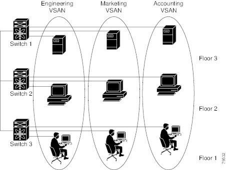
Figure 1-2 shows a physical Fibre Channel switching infrastructure with two defined VSANs: VSAN 2 (dashed) and VSAN 7 (solid). VSAN 2 includes hosts H1 and H2, application servers AS2 and AS3, and storage arrays SA1 and SA4. VSAN 7 connects H3, AS1, SA2, and SA3.
Figure 1-2 Example of Two VSANs
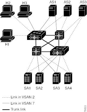
The four switches in this network are interconnected by trunk links that carry both VSAN 2 and
VSAN 7 traffic. The inter-switch topology of both VSAN 2 and VSAN 7 are identical. This is not a requirement and a network administrator can enable certain VSANs on certain links to create different VSAN topologies.
Without VSANs, a network administrator would need separate switches and links for separate SANs. By enabling VSANs, the same switches and links may be shared by multiple VSANs. VSANs allow SANs to be built on port granularity instead of switch granularity. Figure 1-2 illustrates that a VSAN is a group of hosts or storage devices that communicate with each other using a virtual topology defined on the physical SAN.
The criteria for creating such groups differ based on the VSAN topology:
–![]() Different customers in storage provider data centers
Different customers in storage provider data centers
–![]() Production or test in an enterprise network
Production or test in an enterprise network
–![]() Low and high security requirements
Low and high security requirements
VSAN Advantages
VSANs offer the following advantages:
- Traffic isolation—Traffic is contained within VSAN boundaries and devices reside only in one VSAN ensuring absolute separation between user groups, if desired.
- Scalability—VSANs are overlaid on top of a single physical fabric. The ability to create several logical VSAN layers increases the scalability of the SAN.
- Per VSAN fabric services—Replication of fabric services on a per VSAN basis provides increased scalability and availability.
- Redundancy—Several VSANs created on the same physical SAN ensure redundancy. If one VSAN fails, redundant protection (to another VSAN in the same physical SAN) is configured using a backup path between the host and the device.
- Ease of configuration—Users can be added, moved, or changed between VSANs without changing the physical structure of a SAN. Moving a device from one VSAN to another only requires configuration at the port level, not at a physical level.
Up to 256 VSANs can be configured in a switch. Of these, one is a default VSAN (VSAN 1), and another is an isolated VSAN (VSAN 4094). User-specified VSAN IDs range from 2 to 4093.
VSANs Versus Zones
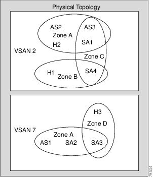
You can define multiple zones in a VSAN. Because two VSANs are equivalent to two unconnected SANs, zone A on VSAN 1 is different and separate from zone A in VSAN 2. Table 1-1 lists the differences between VSANs and zones.
Figure 1-3 shows the possible relationships between VSANs and zones. In VSAN 2, three zones are defined: zone A, zone B, and zone C. Zone C overlaps both zone A and zone B as permitted by Fibre Channel standards. In VSAN 7, two zones are defined: zone A and zone D. No zone crosses the VSAN boundary—they are completely contained within the VSAN. Zone A defined in VSAN 2 is different and separate from zone A defined in VSAN 7.
VSAN Configuration
VSANs have the following attributes:
- VSAN ID—The VSAN ID identifies the VSAN as the default VSAN (VSAN 1), user-defined VSANs (VSAN 2 to 4093), and the isolated VSAN (VSAN 4094).
- State—The administrative state of a VSAN can be configured to an active (default) or suspended state. Once VSANs are created, they may exist in various conditions or states.
–![]() The active state of a VSAN indicates that the VSAN is configured and enabled. By enabling a VSAN, you activate the services for that VSAN.
The active state of a VSAN indicates that the VSAN is configured and enabled. By enabling a VSAN, you activate the services for that VSAN.
–![]() The suspended state of a VSAN indicates that the VSAN is configured but not enabled. If a port is configured in this VSAN, it is disabled. Use this state to deactivate a VSAN without losing the VSAN’s configuration. All ports in a suspended VSAN are disabled. By suspending a VSAN, you can preconfigure all the VSAN parameters for the whole fabric and activate the VSAN immediately.
The suspended state of a VSAN indicates that the VSAN is configured but not enabled. If a port is configured in this VSAN, it is disabled. Use this state to deactivate a VSAN without losing the VSAN’s configuration. All ports in a suspended VSAN are disabled. By suspending a VSAN, you can preconfigure all the VSAN parameters for the whole fabric and activate the VSAN immediately.
- VSAN name—This text string identifies the VSAN for management purposes. The name can be from 1 to 32 characters long and it must be unique across all VSANs. By default, the VSAN name is a concatenation of VSAN and a four-digit string representing the VSAN ID. For example, the default name for VSAN 3 is VSAN0003.

Note![]() A VSAN name must be unique.
A VSAN name must be unique.
- Load balancing attributes—These attributes indicate the use of the source-destination ID (src-dst-id) or the originator exchange OX ID (src-dst-ox-id, the default) for load balancing path selection.
Note![]() OX ID based load balancing of IVR traffic from IVR- enabled switches is not supported on Generation 1 switching modules. OX ID based load balancing of IVR traffic from a non-IVR MDS 9000 Family switch should work. Generation 2 switching modules support OX ID based load balancing of IVR traffic from IVR-enabled switches.
OX ID based load balancing of IVR traffic from IVR- enabled switches is not supported on Generation 1 switching modules. OX ID based load balancing of IVR traffic from a non-IVR MDS 9000 Family switch should work. Generation 2 switching modules support OX ID based load balancing of IVR traffic from IVR-enabled switches.
About VSAN Creation
A VSAN is in the operational state if the VSAN is active and at least one port is up. This state indicates that traffic can pass through this VSAN. This state cannot be configured.
About Port VSAN Membership
Port VSAN membership on the switch is assigned on a port-by-port basis. By default, each port belongs to the default VSAN. You can assign VSAN membership to ports using one of two methods:
See the “Assigning Static Port VSAN Membership” section.
- Dynamically—By assigning VSANs based on the device WWN. This method is referred to as dynamic port VSAN membership (DPVM).
See Chapter1, “Creating Dynamic VSANs”
Trunking ports have an associated list of VSANs that are part of an allowed list ( refer to the Cisco MDS 9000 Family NX-OS Interfaces Configuration Guide).
About the Default VSAN
The factory settings for switches in the Cisco MDS 9000 Family have only the default VSAN 1 enabled. We recommend that you do not use VSAN 1 as your production environment VSAN. If no VSANs are configured, all devices in the fabric are considered part of the default VSAN. By default, all ports are assigned to the default VSAN.
Note![]() VSAN 1 cannot be deleted, but it can be suspended.
VSAN 1 cannot be deleted, but it can be suspended.
Note![]() Up to 256 VSANs can be configured in a switch. Of these, one is a default VSAN (VSAN 1), and another is an isolated VSAN (VSAN 4094). User-specified VSAN IDs range from 2 to 4093.
Up to 256 VSANs can be configured in a switch. Of these, one is a default VSAN (VSAN 1), and another is an isolated VSAN (VSAN 4094). User-specified VSAN IDs range from 2 to 4093.
About the Isolated VSAN
VSAN 4094 is an isolated VSAN. All non-trunking ports are transferred to this VSAN when the VSAN to which they belong is deleted. This avoids an implicit transfer of ports to the default VSAN or to another configured VSAN. All ports in the deleted VSAN are isolated (disabled).
Note![]() When you configure a port in VSAN 4094 or move a port to VSAN 4094, that port is immediately isolated.
When you configure a port in VSAN 4094 or move a port to VSAN 4094, that port is immediately isolated.

Note![]() Up to 256 VSANs can be configured in a switch. Of these, one is a default VSAN (VSAN 1), and another is an isolated VSAN (VSAN 4094). User-specified VSAN IDs range from 2 to 4093.
Up to 256 VSANs can be configured in a switch. Of these, one is a default VSAN (VSAN 1), and another is an isolated VSAN (VSAN 4094). User-specified VSAN IDs range from 2 to 4093.
Operational State of a VSAN
A VSAN is in the operational state if the VSAN is active and at least one port is up. This state indicates that traffic can pass through this VSAN. This state cannot be configured.
About Static VSAN Deletion
When an active VSAN is deleted, all of its attributes are removed from the running configuration. VSAN-related information is maintained by the system software as follows:
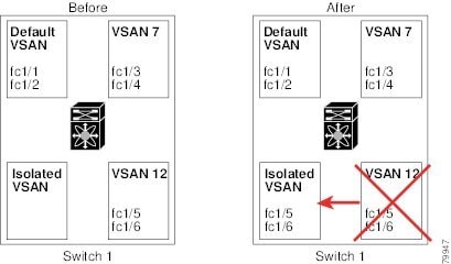
- VSAN attributes and port membership details are maintained by the VSAN manager. This feature is affected when you delete a VSAN from the configuration. When a VSAN is deleted, all the ports in that VSAN are made inactive and the ports are moved to the isolated VSAN. If the same VSAN is recreated, the ports do not automatically get assigned to that VSAN. You must explicitly reconfigure the port VSAN membership (see Figure 1-4).
Figure 1-4 VSAN Port Membership Details
- VSAN-based runtime (name server), zoning, and configuration (static routes) information is removed when the VSAN is deleted.
- Configured VSAN interface information is removed when the VSAN is deleted.
Note![]() The allowed VSAN list is not affected when a VSAN is deleted (refer to the Cisco MDS 9000 Family NX-OS Interfaces Configuration Guide).
The allowed VSAN list is not affected when a VSAN is deleted (refer to the Cisco MDS 9000 Family NX-OS Interfaces Configuration Guide).
Any commands for a nonconfigured VSAN are rejected. For example, if VSAN 10 is not configured in the system, then a command request to move a port to VSAN 10 is rejected.
About Load Balancing
Load balancing attributes indicate the use of the source-destination ID (src-dst-id) or the originator exchange OX ID (src-dst-ox-id, the default) for load balancing path selection.
About Interop Mode
Interoperability enables the products of multiple vendors to come into contact with each other. Fibre Channel standards guide vendors towards common external Fibre Channel interfaces. See the “Switch Interoperability” section.
About FICON VSANs
You can enable FICON in up to eight VSANs. See the “FICON VSAN Prerequisites” section.
Host Provisioning Wizard
The Host Provisioning wizard provides an intuitive way to commission a new host or decomission an existing host without requiring the use of multiple tools and features. The wizard allows you to create a device alias, and configure DPVM, zoning, and flow creation.
Licensing Requirements for VSAN
The following table shows the licensing requirements for this feature:
|
|
|
|---|---|
The enterprise license is required to enable VSAN. For a complete explanation of the licensing scheme, see the Cisco MDS 9000 Family NX-OS Licensing Guide. |
Default Settings
Table 1-2 lists the default settings for all configured VSANs.
|
|
|
|---|---|
Concatenation of VSAN and a four-digit string representing the VSAN ID. For example, VSAN 3 is VSAN0003. |
|
Configuring VSANs
This section includes the following topics:
- Creating VSANs
- Assigning Static Port VSAN Membership
- Deleting Static VSANs
- Commissioning a Host
- Decommissioning a Host
Creating VSANs
Restrictions
You cannot configure any application-specific parameters for a VSAN before creating the VSAN.
Detailed Steps
To create and configure VSANs, follow these steps:
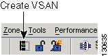
Step 1![]() Click the Create VSAN icon (see Figure 1-5).
Click the Create VSAN icon (see Figure 1-5).
Note![]() As of Cisco SAN-OS Release 3.1(2) and later, if you check the Static Domain IDs check box, DCNM-SAN creates the VSAN in suspended mode and then automatically activates the VSAN.
As of Cisco SAN-OS Release 3.1(2) and later, if you check the Static Domain IDs check box, DCNM-SAN creates the VSAN in suspended mode and then automatically activates the VSAN.
Step 2![]() Check the switches that you want in this VSAN.
Check the switches that you want in this VSAN.
Step 3![]() Fill in the VSAN Name and VSAN ID fields.
Fill in the VSAN Name and VSAN ID fields.
Step 4![]() Set the LoadBalancing value and the InterOperValue.
Set the LoadBalancing value and the InterOperValue.
Step 5![]() Set the Admin State to active or suspended.
Set the Admin State to active or suspended.
Step 6![]() Check the Static Domain Ids check box to assign an unused static domain ID to the VSAN.
Check the Static Domain Ids check box to assign an unused static domain ID to the VSAN.
Step 7![]() (Optional) Select the FICON and Enable Fabric Binding for Selected Switches options if you want these features enabled.
(Optional) Select the FICON and Enable Fabric Binding for Selected Switches options if you want these features enabled.
See the “Configuring FICON” section and refer to the Cisco MDS 9000 Family NX-OS Security Configuration Guide for details.
Step 8![]() Complete the fields in this dialog box and click Create to add the VSAN or click Close.
Complete the fields in this dialog box and click Create to add the VSAN or click Close.
Assigning Static Port VSAN Membership
Detailed Steps
To statically assign VSAN membership for an interface, follow these steps:
Step 1![]() Choose FC Interfaces > Physical from the Physical Attributes pane. You see the interface configuration in the Information pane.
Choose FC Interfaces > Physical from the Physical Attributes pane. You see the interface configuration in the Information pane.
You see the Fibre Channel general physical information. Double-click and complete the PortVSAN field.
Step 3![]() Click Apply Changes to save these changes, or click Undo Changes to discard any unsaved changes.
Click Apply Changes to save these changes, or click Undo Changes to discard any unsaved changes.
Deleting Static VSANs
Detailed Steps
To delete a VSAN and its attributes, follow these steps:
Step 1![]() Select All VSANs from the Logical Domains pane.
Select All VSANs from the Logical Domains pane.
The VSANs in the fabric are listed in the Information pane.
Step 2![]() Right-click the VSAN that you want to delete and select Delete Row from the drop-down menu.
Right-click the VSAN that you want to delete and select Delete Row from the drop-down menu.
You see a confirmation dialog box.
Step 3![]() Click Yes to confirm the deletion or No to close the dialog box without deleting the VSAN.
Click Yes to confirm the deletion or No to close the dialog box without deleting the VSAN.
Configuring Load Balancing
Detailed Steps
To configure load balancing on an existing VSAN, follow these steps:
Step 1![]() Choose Fabricxx > All VSANs from the Logical Domains pane.
Choose Fabricxx > All VSANs from the Logical Domains pane.
You see the VSAN configuration in the Information pane.
Step 2![]() Select a VSAN and complete the LoadBalancing field.
Select a VSAN and complete the LoadBalancing field.
Step 3![]() Click Apply Changes to save these changes, or click Undo Changes to discard any unsaved changes.
Click Apply Changes to save these changes, or click Undo Changes to discard any unsaved changes.
Commissioning a Host
Detailed Steps
To commission a new host, follow these steps:
Step 1![]() From the DCNM-SAN window, select Tools > Host Provisioning.
From the DCNM-SAN window, select Tools > Host Provisioning.
The Host Provisioning wizard window is displayed.
Step 2![]() Click the Commission radio button.
Click the Commission radio button.
Step 3![]() Click [...] and select the host from the existing configurations or VSAN (see Figure 1-6), or enter the WWN of a host that is not in VSAN or not configured yet.
Click [...] and select the host from the existing configurations or VSAN (see Figure 1-6), or enter the WWN of a host that is not in VSAN or not configured yet.
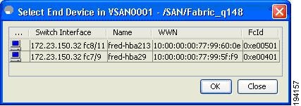
If the host configuration already exists, the switch, device alias, and VSAN information are populated in the window.
If the configuration does not exist already, enter a device alias for the WWN, enter a switch where the configuration will be initiated, and select a VSAN to which the host should belong. The entries are created and saved when you click Next in the Host Provisioning wizard window.
Step 4![]() Uncheck the Skip Zoning check box.
Uncheck the Skip Zoning check box.
Step 5![]() Click Next. The Select Targets and the Select Zone windows appear.
Click Next. The Select Targets and the Select Zone windows appear.
Step 6![]() Uncheck the Skip DPVM check box.
Uncheck the Skip DPVM check box.
Step 7![]() Click Next. The DPVM entries are created.
Click Next. The DPVM entries are created.
The Select Targets window appears.
Note![]() The Host Provisioning wizard requires that basic and enhanced device alias, DPVM, and CFS to be enabled in all switches in the selected VSAN.
The Host Provisioning wizard requires that basic and enhanced device alias, DPVM, and CFS to be enabled in all switches in the selected VSAN.
Step 9![]() Select the target with which the host needs to communicate, and click Add.
Select the target with which the host needs to communicate, and click Add.
The target entry is moved to the bottom of the window.
The Select Zone window appears.
Step 11![]() Select a zone and check the Create Flow after Activation check box.
Select a zone and check the Create Flow after Activation check box.
The host and storage are added to a zone and the zone is activated, and a flow between host and storage is created when you click Finish.
The device alias and DPVM entries are created, a zone is created and activated, and the flow is created based on the check boxes you checked.
Decommissioning a Host
Detailed Steps
To decommission an existing host, follow these steps:
Step 1![]() From the DCNM-SAN window, select Tools > Host Provisioning.
From the DCNM-SAN window, select Tools > Host Provisioning.
The Select Host window appears.
Step 2![]() Click the Decommission radio button.
Click the Decommission radio button.
Step 3![]() Click [...] and select the host from the existing configurations or VSAN, or enter the WWN of a host that is not in VSAN.
Click [...] and select the host from the existing configurations or VSAN, or enter the WWN of a host that is not in VSAN.
The device alias and DPVM state from all of the switches in the selected VSAN are populated if device alias with CFS and CFS DPVM are enabled and if the WWN is an eight-byte number.
Step 4![]() Click Finish. The device aliases are removed.
Click Finish. The device aliases are removed.
Step 5![]() Uncheck the Skip Zoning check box.
Uncheck the Skip Zoning check box.
The WWN zone member is removed from all zones. If the zones without a WWN member become single member zones, these zones also are removed.
Step 6![]() Click Finish. If there is a local active zone set change due to the removal of zones, the appropriate zone set is activated.
Click Finish. If there is a local active zone set change due to the removal of zones, the appropriate zone set is activated.
Step 7![]() Uncheck the Skip DPVM check box.
Uncheck the Skip DPVM check box.
Step 8![]() Click Finish. The DPVM entry is removed.
Click Finish. The DPVM entry is removed.
The Decommission Zones window appears.
Step 10![]() Check the Remove Flow after Deactivation check box.
Check the Remove Flow after Deactivation check box.
The flow entry associated with the host is removed when you click Finish.
The device alias and DPVM entries are deleted, the zone is deactivated and deleted (if it has only one member after removing the host), and the flow is deleted depending on the check boxes you checked.
Verifying VSAN Configuration
Displaying Isolated VSAN Membership
To display interfaces that exist in the isolated VSAN, follow these steps:
Step 1![]() Expand Fabricxx, and then select All VSANs in the Logical Domains pane.
Expand Fabricxx, and then select All VSANs in the Logical Domains pane.
You see the VSAN configuration in the Information pane.
Step 2![]() Click the Isolated Interfaces tab.
Click the Isolated Interfaces tab.
You see the interfaces that are in the isolated VSAN.
Field Descriptions for VSAN
The following are the field descriptions for VSAN.
VSAN General
VSAN Membership
|
|
|
|---|---|
VSAN Interop-4 WWN
|
|
|
|---|---|
VSAN Timers
VSAN Default Zone Policies
Additional References
For additional information related to implementing VSANs, see the following section:
Related Document
|
|
|
|---|---|
Standards
|
|
|
|---|---|
No new or modified standards are supported by this feature, and support for existing standards has not been modified by this feature. |
RFCs
|
|
|
|---|---|
No new or modified RFCs are supported by this feature, and support for existing RFCs has not been modified. |
MIBs
|
|
|
|---|---|
To locate and download MIBs, go to the following URL: http://www.cisco.com/en/US/products/ps5989/prod_technical_reference_list.html |
 Feedback