New and Changed Information
The following table provides an overview of the significant changes to this guide up to this current release. The table does not provide an exhaustive list of all changes that are made to the guide or of the new features up to this release.
|
Cisco APIC Release Version |
Feature |
Description |
Where Documented |
|---|---|---|---|
|
4.2(3) |
A local Layer 3 outside network connection (L3Out) is available for a Cisco Application Centric Infrastructure Virtual Edge that is connected to a Cisco ACI Virtual Pod. |
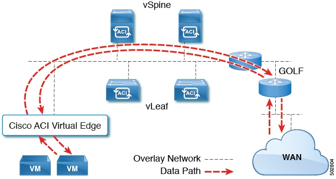
WAN traffic from Cisco ACI Virtual Edge attached to a Cisco ACI Virtual Pod no longer must go through an L3Out on a physical leaf in the on-premises data center. You can now configure the fabric to send traffic to leave a Cisco Cloud Service Router (CSR) using Cisco GOLF in the remote location. |
|
Cisco ACI vPod: Enabling Outside Communication with Devices in the Remote Location
Beginning in Cisco Application Policy Infrastructure Controller (APIC) Release 4.2(1), you can improve the efficiency of a network that is extended to a remote site. You can do so by configuring a Layer 3 outside network connection (L3Out) through Cisco Application Centric Infrastructure (ACI) Virtual Pod (vPod) in the remote site.
Before Cisco APIC Release 4.2(1), to connect to outside networks, Cisco ACI vPod had to use an L3Out on a physical leaf in the on-premises data center. However, you can now configure an L3Out directly through a Cisco Cloud Services Router (CSR) using the Cisco ACI GOLF feature.
The new direct L3Out configuration is simpler and more efficient than communicating over the interpod network (IPN) connection to the on-premises data center. Connecting through an L3Out and Cisco Cloud Services Router in the remote location provides greater bandwith and lower latency than connecting through the IPN to the physical leaf.
You configure the L3Out for Cisco ACI vPod as you configure an L3Out for Cisco ACI GOLF in Cisco APIC. This guide provides the following information:
-
Information about Cisco ACI vPod
-
Procedures for configuring L3Out
-
Links to more Cisco ACI vPod and Cisco ACI documentation
Cisco ACI vPod: Extending the Cisco ACI Fabric
Organizations increasingly adopt hybrid data center models to meet infrastructure demands, flexibility, and reduce costs. They combine various technologies—including virtual private clouds and other internal IT resources—with remote locations. The remote locations can be hosted data centers, satellite data centers, or multicloud environments.
However, hybrid deployments require consistent management and policy for workloads regardless of their location. They also require support for disaster recovery and the ability to migrate workloads between data centers. Meanwhile, they can lack compatible hardware or space to add new equipment.
By deploying Cisco Application Centric Infrastructure (ACI) Virtual Pod (vPod), you can overcome these challenges and virtually extend the Cisco ACI fabric into various remote locations.
What Cisco ACI vPod Is
Cisco ACI vPod was introduced with general availability in Cisco APIC Release 4.0(2). It is a software-only solution that you can deploy wherever you have at least two servers on which you can run the VMware ESXi hypervisor. Cisco ACI vPod and its components—a virtual spine (vSpine), virtual leaf (vLeaf), and Cisco ACI Virtual Edge, run on the ESXi hypervisor.
Cisco ACI vPod allows you to use Cisco ACI Virtual Edge where you do not have a physical leaf. You can use up to eight instances of Cisco ACI Virtual Edge in each Cisco ACI vPod in the remote location as you would in your on-premises data center.
Cisco ACI vPod communicates with a physical, on-premises pod or multipod over an interpod network (IPN). You configure the physical pod or multipod, the IPN connection, and Cisco ACI vPod in Cisco Application Policy Infrastructure Controller (APIC). You then use the Cisco ACI vCenter plug-in, a Python script, or PowerCLI to deploy Cisco ACI vPod components.
Benefits of Cisco ACI vPod
Once Cisco ACI vPod is installed, you can use it with Cisco APIC to enforce Cisco ACI fabric policy in the remote location.
Cisco APIC provides central management of workloads in the on-premises data center and the remote location. It enables you to enforce policy easily and consistently in both on-premises and remote locations.
The flexibility, scalability, and central management of the Cisco ACI vPod solution enable you to take advantage of the following use case scenarios:
-
Extension of the Cisco ACI fabric to the bare-metal cloud
-
Extension of the Cisco ACI fabric to brownfield deployments
-
Extension of the Cisco ACI fabric to colocation data centers
-
Migration of workloads from non-Cisco hardware to the Cisco ACI fabric
Where to Find More Information
For general information, see the Cisco ACI Virtual Pod Release Notes on Cisco.com.
Cisco ACI vPod Architecture
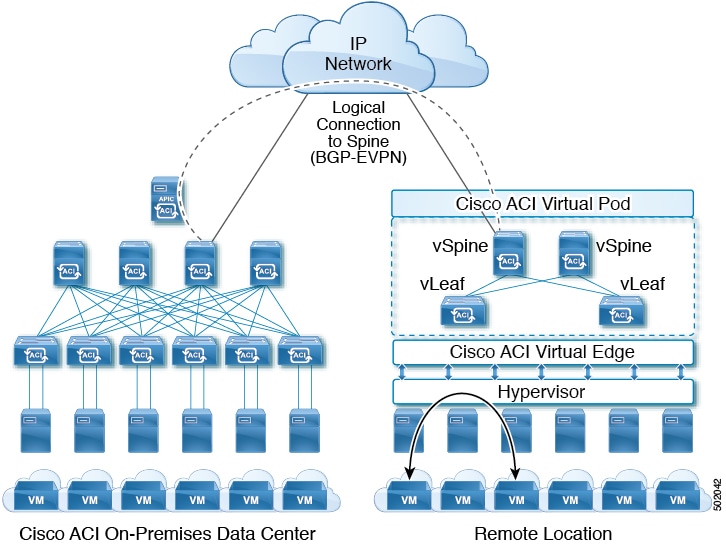
Cisco Application Centric Infrastructure (ACI) Virtual Pod (vPod) extends the multipod architecture into the virtual infrastructure. It consists of virtual spines (vSpines), virtual leafs (vLeafs), and one to 32 instances of Cisco ACI Virtual Edge. These elements are deployed on a VMware ESXi hypervisor in the remote location.
The vSpines and Cisco ACI Virtual Edge logically connect to the on-premises data center over an interpod network (IPN). The Cisco Application Policy Infrastructure Controller (APIC) cluster in the on-premises data center discovers, configures, and extends the policy on the Cisco ACI vPod.
Cisco ACI vPod includes the following elements:
-
Virtual spine (vSpine) and Virtual leaf (vLeaf): The vSpine and vLeaf are separate virtual machines (VMs) within Cisco ACI vPod. They emulate the functionality of a physical spine and physical leaf. The vSpines and Cisco ACI Virtual Edge logically connect to the on-premises data center over an IPN.
The vSpine and vLeaf function as services inside the VMs in the Cisco ACI vPod, handling control plane management. They are contained in the Cisco ACI vPod installation package.
-
vSpine: Establishes a Border Gateway Protocol (BGP) Ethernet VPN (EVPN) connection to the on-premises spine and the vPod control plane.
-
vLeaf: Distributes the policies that are created on Cisco Application Policy Infrastructure Controller (APIC) to the Cisco ACI Virtual Edge.
-
-
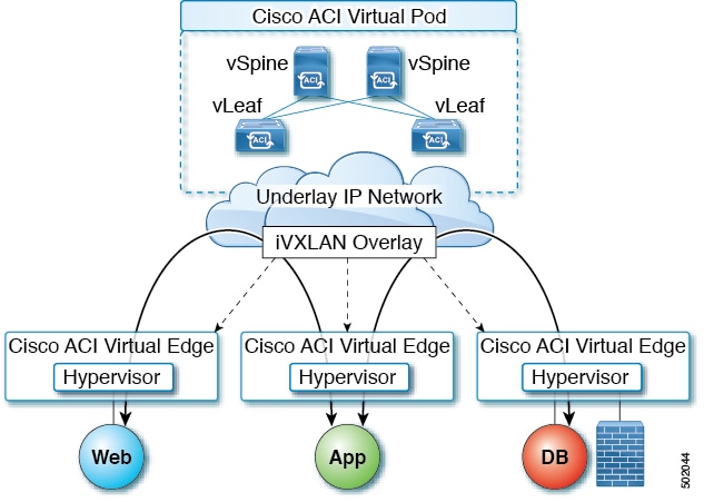
Cisco ACI Virtual Edge: Connects to spines and border leaves in the physical Cisco ACI fabric through Insieme VXLAN (iVXLAN) tunnels. It also uses iVXLAN for communication within the remote site. Cisco ACI Virtual Edge handles packet forwarding, policy enforcement, and all data plane management. The iVXLAN overlay technology in the data plane provides Layer 2 and Layer 3 connectivity services between endpoints, regardless of their location.
You deploy one Cisco ACI Virtual Edge on each VMware ESXi hypervisor host that participates in the virtual pod, creating a distributed data plane across the virtual pod. You can have up to 32 Cisco ACI Virtual Edge virtual leafs in a Cisco ACI vPod, one on each host.
Cisco ACI Virtual Edge uses the fast packet-processing framework Data Plane Development Kit (DPDK) for high-performance forwarding in the user space.
A single Cisco ACI can contain multiple physical pods and multiple virtual pods. A single Cisco APIC manages the entire fabric. Tenant configurations—including virtual routing and forwarding (VRF), bridge domains, and endpoint groups (EPGs)—are available across all the pods.
Cisco ACI vPod Licensing
You obtain the following two licenses for Cisco Application Centric Infrastructure (ACI) Virtual Pod (vPod) on Cisco.com:
-
Management Cluster: You need a single license for each Cisco ACI vPod.
The management cluster is licensed as a pair of redundant virtual spine (vSpine) and virtual leaf (vLeaf) virtual machines (VMs). The cluster provides Cisco ACI management and control plane functions. It also programs the individual Cisco Application Centric Infrastructure Virtual Edge within the Cisco ACI vPod.
The single Cisco ACI vPod management cluster license includes the redundant vSpines and vLeafs, a total of four VMs.

Note
VMware ESXi 6.0 or later is required for the management cluster.
-
Cisco ACI Virtual Edge: You need one license for each instance of Cisco ACI Virtual Edge; you can have up to 32 instances on each Cisco ACI vPod.
Cisco ACI Virtual Edge is licensed in vPod mode, when it is part of Cisco ACI vPod. It is licensed as a VM that operates on each workload server. It provides data plane and policy enforcement functions. (Cisco ACI Virtual Edge is not licensed when installed on a physical leaf—when it functions outside of Cisco ACI vPod deployments.)
Note
VMware ESXi 6.0 or later is required for the workload.
Cisco ACI vPod in a Multipod Environment
Cisco Application Centric Infrastructure (ACI) Virtual Pod (vPod) can be used with multipod Cisco ACI fabrics. You must configure an interpod network (IPN) connection to a physical pod in the on-premises data center before you can add the Cisco ACI vPod.
Multipod environments enable a more fault-tolerant fabric comprising multiple pods with isolated control plane protocols. They also provide greater flexibility in full mesh cabling between leaf and spine switches.
For detailed information about multipod environments, see the following documents on Cisco.com:
-
Cisco Application Centric Infrastructure Fundamentals
-
Cisco Layer 3 Network Configuration Guide
-
Cisco APIC NX-OS Style Command-Line Interface Configuration Guide
See the Cisco ACI Virtual Edge Release Notes for information about Cisco Application Centric Infrastructure Virtual Edge for features not supported with multipod.
Local L3Out Configuration for Cisco ACI vPod
This section provides the information that you need—including prerequisites and procedures—to enable local Layer 3 outside network configuration (L3out) for Cisco Application Centric Infrastructure (ACI) Virtual Pod (vPod).
Prerequisites for Cisco ACI vPod L3Out Configuration
You must have performed the following tasks before you can improve network efficiency by configuring a Layer 3 outside (L3Out) connection for Cisco Application Centric Infrastructure (ACI) Virtual Pod (vPod).
-
Have installed a Cisco Application Centric Infrastructure (ACI) fabric, including Cisco Application Policy Infrastructure Controller (APIC).
See the Cisco APIC Getting Started Guide and the Cisco APIC Basic Configuration Guide on Cisco.com for details.
-
Installed Cisco Application Centric Infrastructure (ACI) Virtual Pod (vPod) in a remote location.
See the Cisco ACI Virtual Pod Installation Guide and Cisco ACI Virtual Pod Getting Started Guide on Cisco.com for details.
-
Configured the external router connectivity with Cisco ACI vPod to communicate with virtual spines for local L3Out configuration.
Cisco ACI GOLF is supported on CSR1000V, ASR1000, ASR9000 and Nexus 7000.
-
Have read and followed the guidelines for configuring tenant Cisco ACI GOLF.
See the chapter "Routed Connectivity to External Networks" in the Cisco APIC Layer 3 Networking Configuration Guide.
-
Have read the chapter "Cisco ACI GOLF" in the Cisco APIC Layer 3 Networking Configuration Guide.
The GOLF feature and its configuration are nearly identical to those of Cisco ACI vPod L3Out.
Workflow for Cisco ACI vPod L3Out Configuration
This section provides a high-level description of the tasks that are required to configure a Layer 3 outside network connection (L3Out) through the Cisco Application Centric Infrastructure (ACI) Virtual Pod (vPod).
-
Fulfill all the prerequisites, which include meeting all hardware and software requirements.
See the section Prerequisites for Cisco ACI vPod L3Out Configuration in this guide.
-
Create a tenant, virtual routing and forwarding (VRF) instance for the tenant, and a bridge domain on a virtual leaf in the remote site.
See the section Create a Tenant, VRF, and Bridge Domain in this guide.
-
Create an application profile.
See the section Creating an Application Profile Using the GUI in this guide.
-
Create endpoint groups (EPGs) that will consume the L3Out.
See the section Creating EPGs in this guide.
-
Configure the L3Out for the created VRF.
See the section Configuring an L3Out Using Cisco ACI GOLF in this guide.
Create a Tenant, VRF, and Bridge Domain
Complete the procedure in this section to create a tenant, virtual routing and forwarding (VRF) instance, and a bridge domain.
Procedure
| Step 1 |
On the menu bar, choose . |
| Step 2 |
In the Create Tenant dialog box, perform the following tasks:
|
| Step 3 |
In the Navigation pane, expand , and in the Work pane, drag the VRF icon to the canvas to open the Create VRF dialog box, and perform the following tasks:
|
| Step 4 |
In the Networking pane, drag the BD icon to the canvas while connecting it to the VRF icon. In the Create Bridge Domain dialog box that displays, perform the following tasks:
|
Creating an Application Profile Using the GUI
SUMMARY STEPS
- On the menu bar, choose TENANTS. In the Navigation pane, expand the tenant, right-click Application Profiles, and click Create Application Profile.
- In the Create Application Profile dialog box, in the Name field, add the application profile name (OnlineStore).
DETAILED STEPS
| Step 1 |
On the menu bar, choose TENANTS. In the Navigation pane, expand the tenant, right-click Application Profiles, and click Create Application Profile. |
| Step 2 |
In the Create Application Profile dialog box, in the Name field, add the application profile name (OnlineStore). |
Creating EPGs
After you create an application profile, you create endpoint groups (EPGs). You can deploy EPGs on specific nodes or ports, or you can associate it to a specific virtual machine manager (VMM) domain.
Deploying an EPG on a Specific Node or Port
Before you begin
You must have created the tenant where you deploy the EPG.
Procedure
| Step 1 |
Log in to the Cisco Application Policy Infrastructure Controller (APIC). |
||||||||
| Step 2 |
Choose . |
||||||||
| Step 3 |
In the left navigation pane, expand tenant, Application Profiles, and the application profile. |
||||||||
| Step 4 |
Right-click Application EPGs and choose Create Application EPG. |
||||||||
| Step 5 |
In the Create Application EPG STEP 1 > Identity dialog box, complete the following steps: |
||||||||
| Step 6 |
In the Create Application EPG STEP 2 > Leaves/Paths dialog box, from the Physical Domain drop-down list, choose a physical domain. |
||||||||
| Step 7 |
Complete one of the following sets of steps:
|
||||||||
| Step 8 |
Click Update and click Finish. |
||||||||
| Step 9 |
In the left navigation pane, expand the EPG that you created. |
||||||||
| Step 10 |
Complete one of the following actions:
|
Creating an EPG and Associating It with a VMM
The port the EPG uses must belong to one of the VM Managers (VMM) or physical domains associated with the EPG.
Procedure
| Step 1 |
On the menu bar, choose Tenants and the tenant where you want to create an EPG. |
| Step 2 |
In the navigation pane, expand the folder for the tenant, the Application Profiles folder, and the folder for the application profile. |
| Step 3 |
Right-click the Application EPG folder, and in the Create Application EPG dialog box, perform the following actions: |
| Step 4 |
In the Create Application Profile dialog box, create two more EPGs. Create the three EPGs—db, app, and web—in the same bridge domain and data center. |
Configuring an L3Out Using Cisco ACI GOLF
This section contains information about Cisco Cisco Application Centric Infrastructure (ACI) GOLF and how to use it to configure a local Layer 3 outside network connection (L3Out).
For general information about Cisco ACI GOLF, see the chapter "Cisco ACI GOLF" in the Cisco APIC Layer 3 Networking Configuration Guide.
Cisco ACI Golf and Cisco ACI vPod
The Cisco Application Centric Infrastructure GOLF feature (also known as Layer 3 Ethernet VPN (EVPN) Services for Fabric WAN) enables much more efficient and scalable Cisco ACI fabric WAN connectivity. It uses the Border Gateway Protocol (BGP) EVPN protocol over IP for WAN routers that are connected to spine switches.
All tenant WAN connections use a single session on the spine switches where the WAN routers are connected. This aggregation of tenant BGP sessions towards the Data Center Interconnect Gateway (DCIG) improves control plane scale by reducing the number of tenant BGP sessions and the amount of configuration required for all of them. The network is extended out using Layer 3 configured on the virtual spine switches. Transit routing with shared services using GOLF is not supported.
A Layer 3 external outside network (L3extOut) for GOLF connectivity for a spine switch is specified under the infra tenant, and includes the following:
-
LNodeP(l3extInstPis not required within the L3Out in the infra tenant.) -
A provider label for the
L3extOutfor GOLF in the infra tenant. -
BGP protocol policies
All regular tenants use the above-defined connectivity. The L3extOut defined in regular tenants requires the following:
-
An
l3extInstP(EPG) with subnets and contracts. The scope of the subnet is used to control import/export route control and security policies. The bridge domain subnet must be set to advertise externally and it must be in the same VRF as the application EPG and the GOLF L3Out EPG. -
Communication between the application EPG and the GOLF L3Out EPG is governed by explicit contracts (not Contract Preferred Groups).
-
An
l3extConsLblconsumer label that must be matched with the same provider label of anL3Outfor GOLF in theinfratenant. Label matching enables application EPGs in other tenants to consume theLNodePexternalL3OutEPG. -
The BGP EVPN session in the matching provider
L3extOutin theinfratenant advertises the tenant routes defined in thisL3Out.
Guidelines and Limitations
Observe the following GOLF guidelines and limitations:
Note |
These guidelines are applicable to both physical pods and Cisco ACI Virtual Pod (vPod). |
-
GOLF routers must advertise at least one route to Cisco ACI in order to accept traffic. No tunnel is created between leaf switches or Cisco ACI Virtual Edge and the external routers until Cisco ACI receives a route from the external routers.
-
All Cisco Nexus 9000 Series ACI-mode switches and all of the Cisco Nexus 9500 platform ACI-mode switch line cards and fabric modules support GOLF. With Cisco Application Policy Infrastructure Controller (APIC) , release 3.1(x) and later, this includes the N9K-C9364C switch.
-
Cisco ACI vPod that correspond to Cisco APIC Release 4.2(3) and later support L3Out over GOLF.
-
At this time, only a single GOLF provider policy can be deployed on spine switch interfaces for the whole fabric.
-
Up to Cisco APIC release 2.0(2), GOLF is not supported with multipod. In release 2.0 (2) the two features are supported in the same fabric only over Cisco Nexus N9000K switches without “EX” on the end of the switch name; for example, N9K-93120TX. Since the 2.1(1) release, the two features can be deployed together over all the switches used in the multipod and EVPN topologies.
-
When configuring GOLF on a spine switch, wait for the control plane to converge before configuring GOLF on another spine switch.
-
In Cisco ACI vPod, at least one virtual spine from each Cisco ACI vPod must establish EVPN BGP peering with external GOLF router(s).
We recommend that you peer both virtual spines from each Cisco ACI vPod with external GOLF router(s).
-
A spine switch can be added to multiple provider GOLF outside networks (GOLF L3Outs), but the provider labels have to be different for each GOLF L3Out. Also, in this case, the OSPF Area has to be different on each of the
L3extOuts and use different loopback addresses. -
The BGP EVPN session in the matching provider
L3Outin theinfratenant advertises the tenant routes defined in thisL3extOut. -
When deploying three GOLF L3Outs, if only 1 has a provider/consumer label for GOLF, and 0/0 export aggregation, APIC will export all routes. This is the same as existing
L3extOuton leaf switches for tenants. -
If there is direct peering between a spine switch and a data center interconnect (DCI) router, the transit routes from leaf switches to the ASR have the next hop as the PTEP of the leaf switch. In this case, define a static route on the ASR for the TEP range of that ACI pod. Also, if the DCI is dual-homed to the same pod, then the precedence (administrative distance) of the static route should be the same as the route received through the other link.
-
The default
bgpPeerPfxPolpolicy restricts routes to 20, 000. For ACI WAN Interconnect peers, increase this as needed. -
In a deployment scenario where there are two
L3extOuts on one spine switch, and one of them has the provider labelprov1and peers with the DCI 1, the secondL3extOutpeers with DCI 2 with provider labelprov2. If the tenant VRF has a consumer label pointing to any 1 of the provider labels (either prov1 or prov2), the tenant route will be sent out both DCI 1 and DCI 2. -
When aggregating GOLF OpFlex VRFs, the leaking of routes cannot occur in the ACI fabric or on the GOLF device between the GOLF OpFlex VRF and any other VRF in the system. An external device (not the GOLF router) must be used for the VRF leaking.
-
A Cisco Cloud Service Router (CSR), or GOLF router, is not controlled by Cisco APIC. Before Cisco APIC Release 4.2(3), physical spine used to push only the VRF configurations to the GOLF router through the OpFlex channel. Because the OpFlex channel is not supported on the virtual spine (vSpine), a network administrator should manually configure the VRF configurations in the GOLF router.
Note |
Cisco ACI does not support IP fragmentation. Therefore, when you configure Layer 3 Outside (L3Out) connections to external routers, or multipod connections through an Inter-Pod Network (IPN), it is critical that the interface MTU is set appropriately on both ends of a link. On some platforms, such as Cisco ACI, Cisco NX-OS, and Cisco IOS, the configurable MTU value does not take into account the Ethernet headers (matching IP MTU, and excluding the 14-18 Ethernet header size), while other platforms, such as IOS-XR, include the Ethernet header in the configured MTU value. A configured value of 9000 results in a maximum IP packet size of 9000 bytes in Cisco ACI, Cisco NX-OS, and Cisco IOS, but results in a maximum IP packet size of 8986 bytes for an IOS-XR untagged interface. For the appropriate MTU values for each platform, see the relevant configuration guides. We highly recommend that you test the MTU using CLI-based commands. For example, on the Cisco NX-OS CLI,use a command such as ping 1.1.1.1 df-bit packet-size 9000 source-interface ethernet 1/1. |
Configure Cisco ACI GOLF for Cisco ACI vPod Using the GUI
The following steps describe how to configure infra GOLF services that any tenant network can consume.
Procedure
| Step 1 |
On the menu bar, click Tenants, then click infra to select the infra tenant. |
| Step 2 |
In the Navigation pane, expand the option and perform the following actions: |
| Step 3 |
Enter the necessary information in the Nodes and Interfaces window of the Create L3Out wizard. |
| Step 4 |
In the Create Infra BGP Peer Connectivity Profile window of the Create L3Out wizard, enter the necessary information. |
| Step 5 |
Enter the necessary information in the External EPG window of the Create L3Out wizard. |
| Step 6 |
In the Navigation pane for any tenant, expand the and perform the following actions: |
| Step 7 |
In the External EPG dialog box, complete the following steps:
|
 Feedback