Cisco APIC Getting Started Guide, Release 1.2(x) and Release 1.3(x)
Bias-Free Language
The documentation set for this product strives to use bias-free language. For the purposes of this documentation set, bias-free is defined as language that does not imply discrimination based on age, disability, gender, racial identity, ethnic identity, sexual orientation, socioeconomic status, and intersectionality. Exceptions may be present in the documentation due to language that is hardcoded in the user interfaces of the product software, language used based on RFP documentation, or language that is used by a referenced third-party product. Learn more about how Cisco is using Inclusive Language.
- Updated:
- December 7, 2015
Chapter: Using the Basic GUI
- Toggling Between Basic and Advanced GUI Modes
- About Getting Started with APIC Examples
- About Switch Discovery with the APIC
- Switch Registration with the APIC Cluster
- Switch Discovery Validation and Switch Management from the APIC
- Validating the Fabric Topology
- Unmanaged Switch Connectivity in VM Management
- Time Synchronization and NTP
- In-Band and Out-of-Band Management NTP
- NTP over IPv6
- Configuring NTP Using the Basic GUI
- Verifying NTP Policy Deployed to Each Node Using the CLI
- Creating User Accounts
- Adding Management Access in the GUI
- Configuring Virtual Machine Networking Policies
- About the VM Manager
- Prerequisites for Creating a VMM Domain Profile
- Custom User Account with Minimum VMware vCenter Privileges
- Creating a VMM Domain Profile
- Creating a vCenter Domain Profile Using the Basic GUI
- Creating a vCenter and a vShield Domain Profile Using the Basic GUI
- Configuring a DHCP Relay Policy
- Configuring a DNS Service Policy
- Configuring External Destinations with an In-Band DNS Service Policy
- Policy for Priority of IPv4 or IPv6 in a DNS Profile
- Configuring a DNS Service Policy to Connect with DNS Providers Using the Basic GUI
- Verifying that the DNS Profile is Configured and Applied to the Fabric Controller Switches Using the CLI
Using the Basic
GUI
This chapter contains the following sections:
- Toggling Between Basic and Advanced GUI Modes
- About Getting Started with APIC Examples
- About Switch Discovery with the APIC
- Creating User Accounts
- Adding Management Access in the GUI
- Configuring a VMM Domain
- Creating Tenants, VRF, and Bridge Domains
- Configuring Server or Service Policies
- Configuring External Connectivity for Tenants
- Deploying an Application Policy
Toggling Between Basic and Advanced GUI Modes
When logged in to the APIC GUI, you can verify the GUI mode you are in. The mode you have entered is displayed in the top right corner of the GUI. You can choose to operate in one of two modes:
Caution: Cisco recommends that you do not mix configuration modes (Advanced or Basic). When you make a configuration in either mode and change the configuration using the other mode, unintended changes can occur. For example, if you apply an interface policy to two ports using Advanced mode and then change the settings of one port using Basic mode, your changes might be applied to both ports.
-
Basic Mode—For information about tasks that you perform in Basic Mode, see the chapter,Getting Started with APIC Using the Basic GUI.
-
Advanced Mode—For information about tasks that you perform in Advanced Mode, see the chapter,Getting Started with APIC Using the Advanced GUI.
You can also change from one GUI mode to another or toggle between modes as follows:
-
In the GUI, click the welcome, <login_name> drop-down list and choose Toggle GUI Mode.
-
In the Warning dialog box, click Yes .
-
Wait for the application to complete loading and display the GUI in the changed mode.

For the steps to remove such objects, see Troubleshooting Unwanted _ui_ Objects in the APIC Troubleshooting Guide.
About Getting Started with APIC Examples
The steps in several examples in this guide include a parameter name. These parameter names are provided as examples for convenience and ease of your understanding, and it is not required for you to use them.
About Switch Discovery with the APIC
The APIC is a central point of automated provisioning and management for all the switches that are part of the ACI fabric. A single data center might include multiple ACI fabrics; each data center might have its own APIC cluster and Cisco Nexus 9000 Series switches that are part of the fabric. To ensure that a switch is managed only by a single APIC cluster, each switch must be registered with that specific APIC cluster that manages the fabric.
The APIC discovers new switches that are directly connected to any switch it currently manages. Each APIC instance in the cluster first discovers only the leaf switch to which it is directly connected. After the leaf switch is registered with the APIC, the APIC discovers all spine switches that are directly connected to the leaf switch. As each spine switch is registered, that APIC discovers all the leaf switches that are connected to that spine switch. This cascaded discovery allows the APIC to discover the entire fabric topology in a few simple steps.
- Switch Registration with the APIC Cluster
- Switch Discovery Validation and Switch Management from the APIC
- Validating the Fabric Topology
- Unmanaged Switch Connectivity in VM Management
Switch Registration with the APIC Cluster
 Note | Before you begin registering a switch, make sure that all switches in the fabric are physically connected and booted in the desired configuration. For information about the installation of the chassis, see http://www.cisco.com/c/en/us/support/cloud-systems-management/application-policy-infrastructure-controller-apic/products-installation-guides-list.html. |
After a switch is registered with the APIC, the switch is part of the APIC-managed fabric inventory. With the Application Centric Infrastructure fabric (ACI fabric), the APIC is the single point of provisioning, management, and monitoring for switches in the infrastructure.
Note | The infrastructure IP address range must not overlap with other IP addresses used in the ACI fabric for in-band and out-of-band networks. |
Registering the Unregistered Switches Using the GUI
Note | The infrastructure IP address range must not overlap with other IP addresses used in the ACI fabric for in-band and out-of-band networks. |
Make sure that all switches in the fabric are physically connected and booted.
Switch Discovery Validation and Switch Management from the APIC
After the switches are registered with the APIC, the APIC performs fabric topology discovery automatically to gain a view of the entire network and to manage all the switches in the fabric topology.
Each switch can be configured, monitored, and upgraded from the APIC without having to access the individual switches.
Validating the Registered Switches Using the GUI
Validating the Fabric Topology
After all the switches are registered with the APIC cluster, the APIC automatically discovers all the links and connectivity in the fabric and discovers the entire topology as a result.
Validating the Fabric Topology Using the GUI
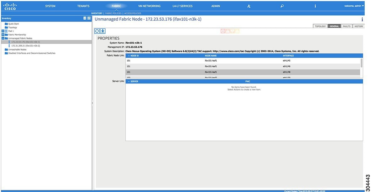
Unmanaged Switch Connectivity in VM Management
Time Synchronization and NTP
Within the Cisco Application Centric Infrastructure (ACI) fabric, time synchronization is a crucial capability upon which many of the monitoring, operational, and troubleshooting tasks depend. Clock synchronization is important for proper analysis of traffic flows as well as for correlating debug and fault time stamps across multiple fabric nodes.
An offset present on one or more devices can hamper the ability to properly diagnose and resolve many common operational issues. In addition, clock synchronization allows for the full utilization of the atomic counter capability that is built into the ACI upon which the application health scores depend. Nonexistent or improper configuration of time synchronization does not necessarily trigger a fault or a low health score. You should configure time synchronization before deploying a full fabric or applications so as to enable proper usage of these features. The most widely adapted method for synchronizing a device clock is to use Network Time Protocol (NTP).
Prior to configuring NTP, consider what management IP address scheme is in place within the ACI fabric. There are two options for configuring management of all ACI nodes and Application Policy Infrastructure Controllers (APICs), in-band management and/or out-of-band management. Depending upon which management option is chosen for the fabric, configuration of NTP will vary. Another consideration in deploying time synchronization is where the time source is located. The reliability of the source must be carefully considered when determining if you will use a private internal clock or an external public clock.
In-Band and Out-of-Band Management NTP
-
Out-of-band management NTP—When an ACI fabric is deployed with out-of-band management, each node of the fabric, inclusive of spines, leaves, and all members of the APIC cluster, is managed from outside the ACI fabric. This IP reachability will be leveraged so that each node can individually query the same NTP server as a consistent clock source. To configure NTP, a Date and Time policy must be created that references an out-of-band management endpoint group. Date and Time policies are confined to a single pod and must be deployed across all pods provisioned in the ACI fabric. Currently only one pod per ACI fabric is allowed.
-
In-Band Management NTP—When an ACI fabric is deployed with in-band management, consider the reachability of the NTP server from within the ACI in-band management network. In-band IP addressing used within the ACI fabric is not reachable from anywhere outside the fabric. To leverage an NTP server external to the fabric with in-band management, construct a policy to enable this communication. The steps used to configure in-band management policies are identical to those used to establish an out-of-band management policy. The distinction is around how to allow the fabric to connect to the NTP server.
NTP over IPv6
NTP over IPv6 addresses is supported in hostnames and peer addresses. The gai.conf can also be set up to prefer the IPv6 address of a provider or a peer over an IPv4 address. The user can provide a hostname that can be resolved by providing an IP address (both IPv4 or IPv6, depending on the installation or preference).
Configuring NTP Using the Basic GUI
Verifying NTP Policy Deployed to Each Node Using the CLI
Creating User Accounts
Configuring a Local User
In the initial configuration script, the admin account is configured and the admin is the only user when the system starts. The APIC supports a granular, role-based access control system where user accounts can be created with various roles including non-admin users with fewer privileges.
Configuring a Remote User
Instead of configuring local users, you can point the APIC at the centralized enterprise credential datacenter. The APIC supports Lightweight Directory Access Protocol (LDAP), active directory, RADIUS, and TACACS+.
Note | When an APIC is in minority (disconnected from the cluster), remote logins can fail because the ACI is a distributed system and the user information is distributed across APICS. Local logins, however, continue to work because they are local to the APIC. |
To configure a remote user authenticated through an external authentication provider, you must meet the following prerequisites:
Configuring a Local User Using the GUI
-
The ACI fabric is installed, APIC controllers are online, and the APIC cluster is formed and healthy.
-
As appropriate, the security domain(s) that the user will access are defined. For example, if the new use account will be restricted to accessing a tenant, the tenant domain is tagged accordingly.
-
An APIC user account is available that will enable the following:
-
Creating the TACACS+ and TACACS+ provider group.
-
Creating the local user account in the target security domain(s). If the target domain is all, the login account used to create the new local user must be a fabric-wide administrator that has access to all. If the target domain is a tenant, the login account used to create the new local user must be a tenant administrator that has full read write access rights to the target tenant domain.
-
AV Pair on the External Authentication Server
The Cisco APIC requires that an administrator configure a Cisco AV Pair on an external authentication server. The Cisco AV pair specifies the APIC required RBAC roles and privileges for the user. The Cisco AV Pair format is the same for RADIUS, LDAP, or TACACS+.
To configure a Cisco AV Pair on an external authentication server, an administrator adds a Cisco AV pair to the existing user record. The Cisco AV pair format is as follows:
shell:domains =
domainA/writeRole1|writeRole2|writeRole3/readRole1|readRole2,
domainB/writeRole1|writeRole2|writeRole3/readRole1|readRole2
shell:domains =
domainA/writeRole1|writeRole2|writeRole3/readRole1|readRole2,
domainB/writeRole1|writeRole2|writeRole3/readRole1|readRole2(16003)
The first av-pair format has no UNIX user ID, while the second one does. Both are correct if all remote users have the same role and mutual file access is acceptable. If the UNIX user ID is not specified, ID 23999 is applied by the APIC system, and more than one role/read privilege is specified to any AV Pair user. This can cause users to have higher or lower permissions than configured through the group settings.
Note | The APIC Cisco AV-pair format is compatible and can co-exist with other Cisco AV-pair formats. APIC will pick up the first matching AV-pair from all the AV-pairs. |
The APIC supports the following regexes:
shell:domains\\s*[=:]\\s*((\\S+?/\\S*?/\\S*?)(,\\S+?/\\S*?/\\S*?){0,31})(\\(\\d+\\))$
shell:domains\\s*[=:]\\s*((\\S+?/\\S*?/\\S*?)(,\\S+?/\\S*?/\\S*?){0,31})$
Examples:
-
Example 1: A Cisco AV Pair that contains a single Login domain with only writeRoles: shell:domains=domainA/writeRole1|writeRole2/
-
Example 2: A Cisco AV Pair that contains a single Login domain with only readRoles: shell:domains=domainA//readRole1|readRole2
Note | The "/" character is a separator between writeRoles and readRoles per Login domain and is required even if only one type of role is to be used. The Cisco AVpair string is case sensitive. Although a fault may not be seen, using mismatching cases for the domain name or roles could lead to unexpected privileges being given. |
An example configuration for an open RADIUS server (/etc/raddb/users) is as follows:
aaa-network-admin Cleartext-Password := "<password>"
Cisco-avpair = "shell:domains = all/aaa/read-all(16001)"
- Changing the Default Behavior for Remote Users with Missing or Bad Cisco AV Pairs
- Best Practice for Assigning AV Pairs
- Configuring an AV Pair on the External Authentication Server
Changing the Default Behavior for Remote Users with Missing or Bad Cisco AV Pairs
Best Practice for Assigning AV Pairs
As best practice, Cisco recommends that you assign unique UNIX user ids in the range 16000-23999 for the AV Pairs that are assigned to users when in bash shell (using SSH, Telnet or Serial/KVM consoles). If a situation arises when the Cisco AV Pair does not provide a UNIX user id, the user is assigned a user id of 23999 or similar number from the range that also enables the user's home directories, files, and processes accessible to remote users with a UNIX ID of 23999.
The Cisco AVpair string is case sensitive. Although a fault may not be seen, using mismatching cases for the domain name or roles could lead to unexpected privileges being given.
Configuring an AV Pair on the External Authentication Server
The numerical value within the parentheses in the attribute/value (AV) pair string is used as the UNIX user ID of the user who is logged in using Secure Shell (SSH) or Telnet.
Configuring a Remote User Using the GUI
Adding Management Access in the GUI
An APIC controller has two routes to reach the management network, one is by using the in-band management interface and the other is by using the out-of-band management interface.
The in-band management network allows APIC to communicate with the leaf switches and with the outside using the ACI fabric, and it makes it possible for external management devices to communicate with the APIC or the leaf switches and spine switches using the fabric itself.
The out-of-band management network configuration defines the configuration of the management port on the controllers, the leaf switches and the spine switches.
The APIC controller always selects the in-band management interface over the out-of-band management interface, if the in-band management interface is configured. The out-of-band management interface is used only when the in-band management interface is not configured or if the destination address is on the same subnet as the out-of-band management subnet of the APIC. This behavior cannot be changed or reconfigured. The APIC management interface does not support an IPv6 address and cannot connect to an external IPv6 server through this interface.
The APIC out-of-band management connection link must be 1 Gbps.
- IPv4/IPv6 Addresses and In-Band Policies
- IPv4/IPv6 Addresses in Out-of-Band Policies
- Configuring Management Access
IPv4/IPv6 Addresses and In-Band Policies
In-band management addresses can be provisioned on the APIC controller only through a policy (Postman REST API, NX-OS Style CLI, or GUI). Additionally, the in-band management addresses must be configured statically on each node.
IPv4/IPv6 Addresses in Out-of-Band Policies
Out-of-band management addresses can be provisioned on the APIC controller either at the time of bootstrap or by using a policy (Postman REST API, NX-OS Style CLI, GUI). Additionally, the out-of-band management addresses must be configured statically on each node or by specifying a range of addresses (IPv4/IPv6) to the entire cluster. IP addresses are randomly assigned from a range to the nodes in the cluster.
Configuring Management Access
Configuring In-Band Management Access Using the Basic GUI
Note | IPv4 and IPv6 addresses are supported for in-band management access. IPv6 configurations are supported using static configurations (for both in-band and out-of-band). IPv4 and IPv6 dual in-band and out-of-band configurations are supported only through static configuration. For more information, see the KB article, Configuring Static Management Access in Cisco APIC. |
The in-band management access is now established.
Configuring Out-of-Band Management Access Using the Basic GUI
Note | IPv4 and IPv6 addresses are supported for out-of-band management access. |
IPv6 Table Modifications to Mirror the Existing IP Tables Functionality
All IPv6 tables mirror the existing IP tables functionality, except for Network Address Translation (NAT).
Existing IP Tables
-
Earlier, every rule in the IPv6 tables were executed one at a time and a system call was made for every rule addition or deletion.
-
Whenever a new policy was added, rules were appended to the existing IP tables file and no extra modifications were done to the file.
-
When a new source port was configured in the out-of-band policy, it added source and destination rules with the same port number.
Modifications to IP Tables
-
When IP tables are created, they are first written into hash maps that are then written into intermediate file IP tables-new which are restored. When saved, a new IP tables file is created in the /etc/sysconfig/ folder. You can find both these files at the same location. Instead of making a system call for every rule, you must make a system call only while restoring and saving the file.
-
When a new policy is added instead of appending it to the file, an IP table is created from scratch, that is by loading default policies into the hashmaps, checking for new policies, and adding them to hashmaps. Later, they are written to the intermediate file (/etc/sysconfig/iptables-new) and saved.
-
It is not possible to configure source ports alone for a rule in out-of-band policy. Either destination port or source port along with a destination port can be added to the rules.
-
When a new policy is added, a new rule will be added to the IP tables file. This rule changes the access flow of IP tables default rules.
-A INPUT -s <OOB Address Ipv4/Ipv6> -j apic-default
-
When a new rule is added, it presents in the IP tables-new file and not in the IP tables file, and it signifies that there is some error in the IP tables-new file. Only if the restoration is successful, the file is saved and new rules are seen in the IP tables file.
Configuring a VMM Domain
Configuring Virtual Machine Networking Policies
The APIC integrates with third-party VM manager (VMM) (for example, VMware vCenter and SCVMM) to extend the benefits of ACI to the virtualized infrastructure. The APIC enables the ACI policies inside the VMM system to be used by its administrator.
This section provides examples of VMM integration using VMware vCenter and vShield. For details about the different modes of Cisco ACI and VMM integration, see the ACI Virtualization Guide.
About the VM Manager
Note | Information about the necessary configuration of the APIC for integration with the vCenter is described here. For instructions about configuring the VMware components, see the VMware documentation. |
The following are details of some VM manager terms:
-
A VM controller is an external virtual machine management entity such as VMware vCenter, and the VMware vShield. The APIC communicates with the controller to publish network policies that are applied to virtual workloads. A VM controller administrator provides an APIC administrator with a VM controller authentication credential; multiple controllers of the same type can use the same credential.
-
Credentials represent the authentication credentials to communicate with VM controllers. Multiple controllers can use the same credentials.
-
A virtual machine mobility domain (vCenter mobility domain) is a grouping of VM controllers with similar networking policy requirements. This mandatory container holds one or more VM controllers with policies such as for a VLAN pool, server to network MTU policy, or server to network access LACP policy. When an endpoint group gets associated with a vCenter domain, network policies get pushed to all the VM controllers in the vCenter domain.
-
A pool represents a range of traffic encapsulation identifiers (for example, VLAN IDs, VNIDs, and multicast addresses). A pool is a shared resource and can be consumed by multiple domains such as VMM and Layer 4 to Layer 7 services. A leaf switch does not support overlapping VLAN pools. You must not associate different overlapping VLAN pools with the VMM domain. The two types of VLAN-based pools are as follows: -
Dynamic pools—Managed internally by the APIC to allocate VLANs for endpoint groups (EPGs). A vCenter Domain can associate only to a dynamic pool.
-
Static pools—The EPG has a relation to the domain, and the domain has a relation to the pool. The pool contains a range of encapsulated VLANs and VXLANs. For static EPG deployment, the user defines the interface and the encapsulation. The encapsulation must be within the range of a pool that is associated with a domain with which the EPG is associated.
-
-
For a VMware vCenter to be deployed, it must operate in VLAN mode or VXLAN mode. A VMM domain must be associated with a VLAN pool and a vShield must be associated with the vCenter.
Prerequisites for Creating a VMM Domain Profile
To configure a VMM domain profile, you must meet the following prerequisites:
-
All fabric nodes are discovered and configured.
-
Inband (inb) or out-of-band (oob) management has been configured on the APIC.
-
A Virtual Machine Manager (VMM) is installed, configured, and reachable through the inb/oob management network (for example, a vCenter).
-
You have the administrator/root credentials to the VMM (for example vCenter).
Note
If you prefer not to use the vCenter admin/root credentials, you can create a custom user account with minimum required permissions. See Custom User Account with Minimum VMware vCenter Privileges for a list of the required user privileges. -
A DNS policy for the APIC must be configured if you plan to reference the VMM by hostname rather than an IP address.
Custom User Account with Minimum VMware vCenter Privileges
This allows the APIC to send VMware API commands to vCenter to allow the creation of the DVS/AVS, creation of the VMK interface (AVS), publish port groups and relay all necessary alerts.
To configure the vCenter from Cisco APIC, your credentials must allow the following minimum set of privileges within the vCenter:
-
Alarms
APIC creates two alarms on the folder. One for DVS and another for port-group. The alarm is raised when the EPG or Domain policy is deleted on APIC, but for port-group or DVS it cannot be deleted due to the VMs are attached.
-
Distributed Switch
-
dvPort Group
-
Folder
-
Network
APIC manages the network settings such as add or delete port-groups, setting host/DVS MTU, LLDP/CDP, LACP etc.
-
Host
If you use AVS in addition to above, you need the Host privilege on the data center where APIC will create DVS.
-
Host.Configuration.Advanced settings
-
Host.Local operations.Reconfigure virtual machine
-
Host.Configuration.Network configuration
This is needed for AVS and the auto-placement feature for virtual Layer 4 to Layer 7 Service VMs. For AVS, APIC creates VMK interface and places it in ‘vtep’ port-group which is used for OpFlex.
-
-
Virtual machine
If you use Service Graph in addition to above, you need the Virtual machine privilege for the virtual appliances which will be used for Service Graph.
Creating a VMM Domain Profile
In this section, examples of a VMM domain are vCenter domain.
Creating a vCenter Domain Profile Using the Basic GUI
Before you create a VMM domain profile, you must establish connectivity to external network using in-band management network on the APIC.
Creating a vCenter and a vShield Domain Profile Using the Basic GUI
| Step 1 | Login to the Basic Mode in the APIC GUI. |
| Step 2 | On the menu bar, choose . |
| Step 3 | In the Navigation pane, right-click VMware and click Create vCenter Domain. |
| Step 4 | In the Create vCenter Domain dialog box, in the Virtual Switch Name field, enter a Name. |
| Step 5 | In the Virtual Switch field, verify that VMware vSphere Distributed Switch is selected. |
| Step 6 | This step
provides the VLAN range for all port groups and EPGs that will be created under
this server. In the
VLAN
Pool drop-down list, choose
Create
VLAN Pool. In the
Create
VLAN Pool dialog box, perform the following actions:
|
| Step 7 | Expand
vCenter/vShield and perform the following tasks:
|
| Step 8 | On the menu bar, choose . |
| Step 9 | In the
Navigation pane, expand
Pod, click on the
Configure tab and perform the following actions:
|
| Step 10 | Verify the new
domain and profiles by performing the following actions:
To ensure that the controllers are operational after the policy has been submitted, the administrator of the vCenter and vShield must add the hosts to the distributed switch. |
Creating Tenants, VRF, and Bridge Domains
Tenants Overview
-
A tenant contains policies that enable qualified users domain-based access control. Qualified users can access privileges such as tenant administration and networking administration.
-
A user requires read/write privileges for accessing and configuring policies in a domain. A tenant user can have specific privileges into one or more domains.
-
In a multitenancy environment, a tenant provides group user access privileges so that resources are isolated from one another (such as for endpoint groups and networking). These privileges also enable different users to manage different tenants.
Tenant Creation
A tenant contains primary elements such as filters, contracts, bridge domains, and application profiles that you can create after you first create a tenant.
VRF and Bridge Domains
You can create and specify a VRF and a bridge domain for the tenant. The defined bridge domain element subnets reference a corresponding Layer 3 context.
For details about enabling IPv6 Neighbor Discovery seeIPv6 and Neighbor Discovery in Cisco APIC Layer 3 Networking Guide.
Creating a Tenant, VRF, and Bridge Domain Using the Basic GUI
| Step 1 | Log in to the Basic Mode in the APIC GUI, and on the menu bar, click . |
| Step 2 | In the Create Tenant dialog box, perform the following tasks: |
| Step 3 | In the Navigation pane, expand , drag the VRF icon to the canvas to open the Create VRF dialog box, and perform the following tasks: |
| Step 4 | In the Networking pane, drag the BD icon to the canvas while connecting it to the VRF icon. In the Create Bridge Domain dialog box that displays, perform the following tasks: |
| Step 5 | In the
Networking pane, drag the
L3 icon down to the canvas while connecting it to
the
VRF icon. In the
Create
Routed Outside dialog box that displays, perform the following
tasks:
|
Configuring Server or Service Policies
Configuring a DHCP Relay Policy
A DHCP relay policy may be used when the DHCP client and server are in different subnets. If the client is on an ESX hypervisor with a deployed vShield Domain profile, then the use of a DHCP relay policy configuration is mandatory.
When a vShield controller deploys a Virtual Extensible Local Area Network (VXLAN), the hypervisor hosts create a kernel (vmkN, virtual tunnel end-point [VTEP]) interface. These interfaces need an IP address in the infrastructure tenant that uses DHCP. Therefore, you must configure a DHCP relay policy so that the APIC can act as the DHCP server and provide these IP addresses.
When an ACI fabric acts as a DHCP relay, it inserts the DHCP Option 82 (the DHCP Relay Agent Information Option) in DHCP requests that it proxies on behalf of clients. If a response (DHCP offer) comes back from a DHCP server without Option 82, it is silently dropped by the fabric. Therefore, when the ACI fabric acts as a DHCP relay, DHCP servers providing IP addresses to compute nodes attached to the ACI fabric must support Option 82.
Configuring a DHCP Server Policy for the APIC Infrastructure Using the Basic GUI
-
Note
Configuring a DHCP Server Policy is only available in the Advanced Mode. Toggle to the Advanced Mode in the APIC GUI to perform this task.
-
The port and the encapsulation used by the application Endpoint Group must belong to a physical or VM Manager (VMM) domain. If no such association with a domain is established, the APIC continues to deploy the EPG but raises a fault.
-
Cisco APIC supports DHCP relay for both IPv4 and IPv6 tenant subnets. DHCP server addresses can be IPv4 or IPv6. DHCPv6 relay will occur only if IPv6 is enabled on the fabric interface and one or more DHCPv6 relay servers are configured.
Make sure that Layer 2 or Layer 3 management connectivity is configured.
| Step 1 | On the menu bar, choose . In the Navigation pane, under Tenant infra, expand . |
| Step 2 | Right-click Relay Policies and click Create DHCP Relay Policy. |
| Step 3 | In the
Create
DHCP Relay Policy dialog box, perform the following actions:
|
| Step 4 | In the Navigation pane, expand . |
| Step 5 | Right-click DHCP Relay Labels, and click Create DHCP Relay Label. |
| Step 6 | In the
Create
DHCP Relay Label dialog box, perform the following actions:
|
| Step 7 | In the Navigation pane, expand to view the DHCP server created. |
Configuring a DNS Service Policy
A DNS policy is required to connect to external servers, for example AAA, RADIUS, vCenter, and services by hostname. A DNS service policy is a shared policy, so any tenant and VRF that uses this service must be configured with the specific DNS profile label. To configure a DNS policy for the ACI fabric, you must complete the following tasks:
-
Ensure that the management EPG is configured for the DNS policy, otherwise this policy will not take into effect on the switches.
-
Create a DNS profile (default) that contains the information about DNS providers and DNS domains.
-
Associate the DNS profile (default or another DNS profile) name to a DNS label under the required tenant.
It is possible to configure a per-tenant, per-VRF DNS profile configuration. Additional DNS profiles can be created and applied to specific VRFs of specific tenants using the appropriate DNS label. For example, if you create a DNS profile with a name of acme, you can add a DNS label of acme to the appropriate policy configuration in the tenants configuration.
- Configuring External Destinations with an In-Band DNS Service Policy
- Policy for Priority of IPv4 or IPv6 in a DNS Profile
- Configuring a DNS Service Policy to Connect with DNS Providers Using the Basic GUI
- Verifying that the DNS Profile is Configured and Applied to the Fabric Controller Switches Using the CLI
Configuring External Destinations with an In-Band DNS Service Policy
Configure the external destinations for the services as follows:
| Source | In-Band Management | Out-of-Band Management | External Server Location | ||
|---|---|---|---|---|---|
|
APIC |
IP address or Fully Qualified domain name (FQDN) |
IP address or FQDN |
Anywhere |
||
|
Leaf switches |
IP address |
IP address or FQDN
|
Anywhere |
||
|
Spine switches |
IP address |
IP address or FQDN
|
Directly connected to a leaf switch |
The following is a list of external servers:
-
Call Home SMTP server
-
Syslog server
-
SNMP Trap destination
-
Statistics Export destination
-
Configuration Export destination
-
Techsupport Export destination
-
Core Export destination
The recommended guidelines are as follows:
-
The external servers must be atatched to the leaf access ports.
-
Use in-band connectivity for the leaf switches to avoid extra cabling for the management port.
-
Use out-of-band management connectivity for the spine switches. Connect this out-of-band network for spine switches to one of the leaf ports with in-band management virtual routing and forwarding (VRF) so that the spine switches and the leaf switches can reach the same set of external servers.
-
Use IP addresses for the external servers.
Policy for Priority of IPv4 or IPv6 in a DNS Profile
The DNS profile supports version preference choices between IPv4 and IPv6. Using the user interface, you can enable your preference. IPv4 is the default.
The following is an example of a policy based configuration using Postman REST API:
<?xml version="1.0" encoding="UTF-8”?>
<!— api/node/mo/uni/fabric/dnsp-default.xml —>
<dnsProfile dn="uni/fabric/dnsp-default" IPVerPreference="IPv6" childAction="" descr="" >
</dnsProfile>
The gai.conf settings control destination address selection. The file has a label table, precedence table, and an IPv4 scopes table. The changes for prioritizing IPv4 or IPv6 over the other need to go into the precedence table entries. Given below are sample contents of the standard file as it is used in Linux systems for many flavors. A single line of precedence label in the file overrides any default settings.
The following is an example of a gai.conf to prioritize IPv4 over IPv6:
# Generated by APIC
label ::1/128       0
label ::/0          1
label 2002::/16     2
label ::/96         3
label ::ffff:0:0/96 4
precedence  ::1/128       50
precedence ::/0           40
precedence 2002::/16      30
precedence ::/96          20
# For APICs prefering IPv4 connections, change the value to 100.
precedence ::ffff:0:0/96  10
Dual Stack IPv4 and IPv6 DNS Servers
DNS servers have primary DNS records which can be A records (IPV4) or AAAA records (IPV6). Both A and AAAA records associate domain name with a specific IP address (IPv4 or IPv6).
The ACI fabric can be configured to use reputable public DNS servers that run on IPv4. These servers are able to resolve and respond with A record (IPv4) or AAAA record (IPv6).
In a pure IPv6 environment, the system administrators must use IPv6 DNS servers. The IPv6 DNS servers are enabled by adding them to /etc/resolv.conf.
A more common environment is to have dual-stack IPv4 and IPv6 DNS servers. In the dual-stack case, both IPv4 and IPv6 name servers are listed in /etc/resolv.conf. However, in a dual-stack environment, simply appending the IPv6 DNS servers to the list may cause a large delay in DNS resolutions. This is because the IPv6 protocol takes precedence by default, and it is unable to connect to the IPv4 DNS servers (if they are listed first in /etc/resolv.conf). The solution is to list IPv6 DNS servers ahead of IPv4 DNS servers. Also add “options single-request-reopen” to enable the same socket to be used for both IPv4 and IPv6 lookups.
options single-request-reopen
nameserver 2001:4860:4680::8888
nameserver 2001:4860:4680::8844
nameserver 8.8.8.8
nameserver 8.8.4.4
Dual-Stack IPv4 and IPv6 Environment
If the management network in the ACI fabric supports both IPv4 and IPv6, the Linux system application (glibc) will use the IPv6 network by default because getaddrinfo() will return IPv6 first.
Under certain conditions however, an IPv4 address may be preferred over an IPv6 address. The Linux IPv6 stack has a feature which allows an IPv4 address mapped as an IPv6 address using IPv6 mapped IPv4 address (::ffff/96). This allows an IPv6 capable application to use only a single socket to accept or connect both IPv4 and IPv6. This is controlled by the glibc IPv6 selection preference for getaddrinfo() in /etc/gai.conf.
In order to allow glibc to return multiple addresses when using /etc/hosts, “multi on” should be added to the /etc/hosts file. Otherwise, it may return only the first match.
If an application is not aware whether both IPv4 and IPv6 exist, it may not perform fallback attempts using different address families. Such applications may require a fallback implementation.
Configuring a DNS Service Policy to Connect with DNS Providers Using the Basic GUI
Make sure that Layer 2 or Layer 3 management connectivity is configured.
| Step 1 | On the menu bar, choose . In the Navigation pane, expand , and click the default DNS profile. |
| Step 2 | In the Work pane, in the Management EPG field, from the drop-down list, choose the appropriate management EPG (default (Out-of-Band)). |
| Step 3 | Expand
DNS
Providers, and perform the following actions:
|
| Step 4 | Expand
DNS
Domains, and perform the following actions:
|
| Step 5 | Click Submit. The DNS server is configured. |
| Step 6 | On the menu bar, click . |
| Step 7 | In the Navigation pane, expand . |
| Step 8 | In the Work pane, under Properties, in the DNS labels field, enter the appropriate DNS label (default). Click Submit. The DNS profile label is now configured on the tenant and VRF. |
Verifying that the DNS Profile is Configured and Applied to the Fabric Controller Switches Using the CLI
| Step 1 | Verify the configuration for the default DNS profile.
Example: admin@apic1:~> cd /aci/fabric/fabric-policies/global-policies/dns-profiles/default admin@apic1:default> cat summary # dns-profile name : default description : added via CLI by tdeleon@cisco.com ownerkey : ownertag : dns-providers: address preferred -------------- --------- 10.44.124.122 no 10.70.168.183 no 10.37.87.157 no 10.102.6.247 yes dns-domains: name default description --------- ------- ----------- cisco.com yes management-epg : tenants/mgmt/node-management-epgs/default/out-of-band/default |
| Step 2 | Verify the configurations for the DNS labels.
Example: admin@apic1:default> cd /aci/tenants/mgmt/networking/private-networks/oob/dns-profile-labels/default admin@apic1:default> cat summary # dns-lbl name : default description : ownerkey : ownertag : tag : yellow-green |
| Step 3 | Verify that the applied configuration is operating on the fabric
controllers.
Example: admin@apic1:~> cat /etc/resolv.conf # Generated by IFC search cisco.com nameserver 10.102.6.247 nameserver 10.44.124.122 nameserver 10.37.87.157 nameserver 10.70.168.183 admin@apic1:~> ping www.cisco.com PING origin-www.cisco.com (72.163.4.161) 56(84) bytes of data. 64 bytes from www1.cisco.com (72.163.4.161): icmp_seq=1 ttl=238 time=35.4 ms 64 bytes from www1.cisco.com (72.163.4.161): icmp_seq=2 ttl=238 time=29.0 ms 64 bytes from www1.cisco.com (72.163.4.161): icmp_seq=3 ttl=238 time=29.2 ms |
| Step 4 | Verify that the applied configuration is operating on the leaf and
spine switches.
Example: leaf1# cat /etc/resolv.conf search cisco.com nameserver 10.102.6.247 nameserver 10.70.168.183 nameserver 10.44.124.122 nameserver 10.37.87.157 leaf1# cat /etc/dcos_resolv.conf # DNS enabled leaf1# ping www.cisco.com PING origin-www.cisco.com (72.163.4.161): 56 data bytes 64 bytes from 72.163.4.161: icmp_seq=0 ttl=238 time=29.255 ms 64 bytes from 72.163.4.161: icmp_seq=1 ttl=238 time=29.212 ms 64 bytes from 72.163.4.161: icmp_seq=2 ttl=238 time=29.343 ms |
Configuring External Connectivity for Tenants
Before you can distribute the static route to the other leaf switches on the Application Centric Infrastructure (ACI) fabric, a multiprotocol BGP (MP-BGP) process must first be operating, and the spine switches must be configured as BGP route reflectors.
To integrate the ACI fabric into an external routed network, you can configure Open Shortest Path First (OSPF) for management tenant Layer 3 connectivity.
- Configuring an MP-BGP Route Reflector Using the Basic GUI
- Verifying the MP-BGP Route Reflector Configuration
- Creating OSPF External Routed Network for Management Tenant Using Basic GUI
Configuring an MP-BGP Route Reflector Using the Basic GUI
| Step 1 | On the menu bar, choose . | ||
| Step 2 | In the Navigation pane, expand , right-click BGP Route Reflector, and click Create Route Reflector Node Policy EP. | ||
| Step 3 | In the
Create
Route Reflector Node Policy EP dialog box, from the
Spine
Node drop-down list, choose the appropriate spine node. Click
Submit.
| ||
| Step 4 | In the
Autonomous System Number field, choose the
appropriate number. Click
Submit.
|
Verifying the MP-BGP Route Reflector Configuration
| Step 1 | Verify the
configuration by performing the following actions:
|
| Step 2 | Verify that the
autonomous system number is configured in the spine switches by performing the
following actions:
|
Creating OSPF External Routed Network for Management Tenant Using Basic GUI
-
You must verify that the router ID and the logical interface profile IP address are different and do not overlap.
- The following steps are for creating an OSPF external routed network for a management tenant. To create an OSPF external routed network for a tenant, you must choose a tenant and create a VRF for the tenant.
-
For more details, see Cisco APIC and Transit Routing.
| Step 1 | On the menu bar, click . In the Navigation pane, click the leaf switch where you want to deploy the VRF. |
| Step 2 | Right-click and click Configure VRF. |
| Step 3 | In the
Configure
VRF dialog box, perform the following actions:
|
| Step 4 | Expand the Prefix List area. |
| Step 5 | In the
Configure VRF with Leaf dialog box, expand the
OSPF
Configuration area.
|
| Step 6 | In the Navigation pane, expand . |
| Step 7 | Choose the
desired interface where you want to configure Layer 3 and perform the following
actions:
|
The OSPF external routed network for the management tenant is created.
Deploying an Application Policy
Three-Tier Application Deployment
A filter specifies the data protocols to be allowed or denied by a contract that contains the filter. A contract can contain multiple subjects. A subject can be used to realize uni- or bidirectional filters. A unidirectional filter is a filter that is used in one direction, either from consumer-to-provider (IN) or from provider-to-consumer (OUT) filter. A bidirectional filter is the same filter that is used in both directions. It is not reflexive.
Contracts are policies that enable inter-End Point Group (inter-EPG) communication. These policies are the rules that specify communication between application tiers. If no contract is attached to the EPG, inter-EPG communication is disabled by default. No contract is required for intra-EPG communication because intra-EPG communication is always allowed.
Application profiles enable you to model application requirements that the APIC then automatically renders in the network and data center infrastructure. The application profiles enable administrators to approach the resource pool in terms of applications rather than infrastructure building blocks. The application profile is a container that holds EPGs that are logically related to one another. EPGs can communicate with other EPGs in the same application profile and with EPGs in other application profiles.
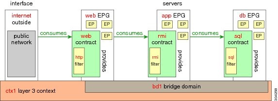
To deploy an application policy, you must create the required application profiles, filters, and contracts. Typically, the APIC fabric hosts a three-tier application within a tenant network. In this example, the application is implemented by using three servers (a web server, an application server, and a database server). See the following figure for an example of a three-tier application.
The web server has the HTTP filter, the application server has the Remote Method Invocation (RMI) filter, and the database server has the Structured Query Language (SQL) filter. The application server consumes the SQL contract to communicate with the database server. The web server consumes the RMI contract to communicate with the application server. The traffic enters from the web server and communicates with the application server. The application server then communicates with the database server, and the traffic can also communicate externally.
Parameters to Create a Filter for http
The parameters to create a filter for http in this example is as follows:
| Parameter Name | Filter for http |
|---|---|
|
Name |
http |
|
Number of Entries |
2 |
|
Entry Name |
Dport-80 Dport-443 |
|
Ethertype |
IP |
|
Protocol |
tcp tcp |
|
Destination Port |
http https |
Parameters to Create Filters for rmi and sql
The parameters to create filters for rmi and sql in this example are as follows:
| Parameter Name | Filter for rmi | Filter for sql |
|---|---|---|
|
Name |
rmi |
sql |
|
Number of Entries |
1 |
1 |
|
Entry Name |
Dport-1099 |
Dport-1521 |
|
Ethertype |
IP |
IP |
|
Protocol |
tcp |
tcp |
|
Destination Port |
1099 |
1521 |
Example Application Profile Database
The application profile database in this example is as follows:
| EPG | Provided Contracts | Consumed Contracts |
|---|---|---|
|
web |
web |
rmi |
|
app |
rmi |
sql |
|
db |
sql |
-- |
Deploying an Application Policy Using the Basic GUI
Verify that the tenant, network, and bridge domain have been created.
| Step 1 |
| ||
| Step 2 | In the Navigation pane, right-click Application Profiles and click Create Application Profile. | ||
| Step 3 | In the Create Application Profile dialog box, enter a name for the profile. Click Submit. | ||
| Step 4 | In the Navigation pane, click and choose the new application profile. | ||
| Step 5 | In the Work pane, from the Drag and drop to configure toolbar, drag and drop the first EPG to the blank screen below. | ||
| Step 6 | In the
Create Application EPG dialog box that is
displayed, perform the following actions:
Repeat this step to create additional EPGs as desired in different bridge domains. | ||
| Step 7 | From the
Drag and drop to configure toolbar, drag and
drop
Contract, and it auto connects as the provider
EPG the consumer EPG as the user desires and drags. The relationship is
displayed with arrows.
The
Config Contract With L4-L7 Service Graph
dialog box is displayed with the selected details auto populated. and the
provider and consumer contracts associated.
| ||
| Step 8 | In the Application Profile Work pane, click Submit. This completes the steps for deploying an application profile. |
 Feedback