- Management Workflows
- Adding Management Access
- In-Band and Out-of-Band Management Access
- Configuring In-Band Management Access Using the Advanced GUI
- Configuring In-Band Management Access Using the NX-OS Style CLI
- Configuring In-Band Management Access Using the REST API
- Configuring Out-of-Band Management Access Using the Advanced GUI
- Configuring Out-of-Band Management Access Using the NX-OS Style CLI
- Configuring Out-of-Band Management Access Using the REST API
- Exporting Tech Support, Statistics, and Core Files
- Overview
- Configuration File Encryption
- Creating a Remote Location Using the GUI
- Configuring an Export Policy Using the GUI
- Configuring an Import Policy Using the GUI
- Configuring an Export Policy Using the NX-OS Style CLI
- Configuring an Import Policy Using the NX-OS Style CLI
- Configuring an Export Policy Using the REST API
- Configuring an Import Policy Using the REST API
- Encrypting Configuration Files Using the GUI
- Encrypting Configuration Files Using the NX-OS Style CLI
- Encrypting Configuration Files Using the REST API
- Backing up, Restoring, and Rolling Back Controller Configuration
- Using Syslog
- Using Atomic Counters
- Using SNMP
Management
This chapter contains the following sections:
- Management Workflows
- Adding Management Access
- Exporting Tech Support, Statistics, and Core Files
- Overview
- Backing up, Restoring, and Rolling Back Controller Configuration
- Using Syslog
- Using Atomic Counters
- Using SNMP
- Using SPAN
- Using Traceroute
Management Workflows
ACI Management Access Workflows
This workflow provides an overview of the steps required to configure management connectivity to switches in the ACI fabric.
|
In-band management access |
Out-of-band management access |
|---|---|
|
|
|
1. Prerequisites
2. Configure the ACI Leaf Switch Access Ports
Choose which of these management access scenarios you will use:
Suggested topics
For additional information, see the following topics:
- Configuring In-Band Management Access Using the Advanced GUI
- Configuring In-Band Management Access Using the NX-OS Style CLI
- Configuring In-Band Management Access Using the REST API
- Configuring Out-of-Band Management Access Using the Advanced GUI
- Configuring Out-of-Band Management Access Using the NX-OS Style CLI
- Configuring Out-of-Band Management Access Using the REST API
Adding Management Access
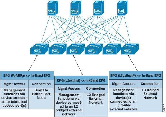
An APIC controller has two routes to reach the management network, one is by using the in-band management interface and the other is by using the out-of-band management interface.
-
In-band management access—You can configure in-band management connectivity to the APIC and the ACI fabric. You first configure the VLANs that will be used by APIC when the APIC is communicating with the leaf switches, and then you configure the VLANs that the VMM servers will use to communicate with the leaf switches.
-
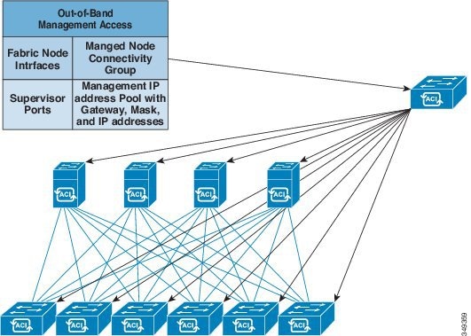
Out-of-band management access—You can configure out-of-band management connectivity to the APIC and the ACI fabric. You configure an out-of-band contract that is associated with an out-of-band endpoint group (EPG), and attach the contract to the external network profile.

Note
The APIC out-of-band management connection link must be 1 Gbps.
The APIC controller always selects the in-band management interface over the out-of-band management interface, if the in-band management interface is configured. The out-of-band management interface is used only when the in-band management interface is not configured, or if the destination address is on the same subnet as the out-of-band management subnet of the APIC. This behavior cannot be changed or reconfigured.
The APIC management interface does not support an IPv6 address and cannot connect to an external IPv6 server through this interface.
Configuring the external management instance profile under the management tenant for in-band or out-of-band has no effect on the protocols that are configured under the fabric-wide communication policies. The subnets and contracts specified under the external management instance profile do not affect HTTP/HTTPS or SSH/Telnet.
- In-Band and Out-of-Band Management Access
- Configuring In-Band Management Access Using the Advanced GUI
- Configuring In-Band Management Access Using the NX-OS Style CLI
- Configuring In-Band Management Access Using the REST API
- Configuring Out-of-Band Management Access Using the Advanced GUI
- Configuring Out-of-Band Management Access Using the NX-OS Style CLI
- Configuring Out-of-Band Management Access Using the REST API
In-Band and Out-of-Band Management Access
The mgmt tenant provides a convenient means to configure access to fabric management functions. While fabric management functions are accessible through the APIC, they can also be accessed directly through in-band and out-of-band network policies.
Configuring In-Band Management Access Using the Advanced GUI
Note |
|
Configuring In-Band Management Access Using the NX-OS Style CLI
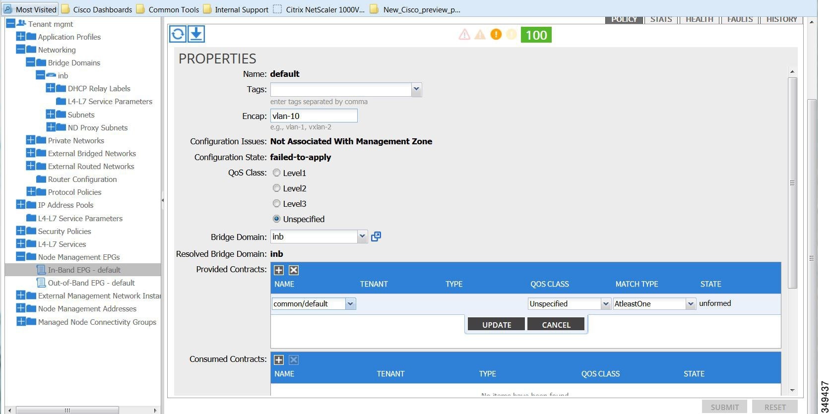
Configuring In-Band Management Access Using the REST API
IPv4 and IPv6 addresses are supported for in-band management access. IPv6 configurations are supported using static configurations (for both in-band and out-of-band). IPv4 and IPv6 dual in-band and out-of-band configurations are supported only through static configuration. For more information, see the KB article,Configuring Static Management Access in Cisco APIC.
| Step 1 | Create a VLAN
namespace.
Example: POST
https://APIC-IP/api/mo/uni.xml
<?xml version="1.0" encoding="UTF-8"?>
<!-- api/policymgr/mo/uni.xml -->
<polUni>
<infraInfra>
<!-- Static VLAN range -->
<fvnsVlanInstP name="inband" allocMode="static">
<fvnsEncapBlk name="encap" from="vlan-10" to="vlan-11"/>
</fvnsVlanInstP>
</infraInfra>
</polUni>
| ||
| Step 2 | Create a
physical domain.
Example: POST
https://APIC-IP/api/mo/uni.xml
<?xml version="1.0" encoding="UTF-8"?>
<!-- api/policymgr/mo/uni.xml -->
<polUni>
<physDomP name="inband">
<infraRsVlanNs tDn="uni/infra/vlanns-inband-static"/>
</physDomP>
</polUni>
| ||
| Step 3 | Create
selectors for the in-band management.
Example: POST
https://APIC-IP/api/mo/uni.xml
<?xml version="1.0" encoding="UTF-8"?>
<!-- api/policymgr/mo/.xml -->
<polUni>
<infraInfra>
<infraNodeP name="vmmNodes">
<infraLeafS name="leafS" type="range">
<infraNodeBlk name="single0" from_="101" to_="101"/>
</infraLeafS>
<infraRsAccPortP tDn="uni/infra/accportprof-vmmPorts"/>
</infraNodeP>
<!-- Assumption is that VMM host is reachable via eth1/40. -->
<infraAccPortP name="vmmPorts">
<infraHPortS name="portS" type="range">
<infraPortBlk name="block1"
fromCard="1" toCard="1"
fromPort="40" toPort="40"/>
<infraRsAccBaseGrp tDn="uni/infra/funcprof/accportgrp-inband" />
</infraHPortS>
</infraAccPortP>
<infraNodeP name="apicConnectedNodes">
<infraLeafS name="leafS" type="range">
<infraNodeBlk name="single0" from_="101" to_="102"/>
</infraLeafS>
<infraRsAccPortP tDn="uni/infra/accportprof-apicConnectedPorts"/>
</infraNodeP>
<!-- Assumption is that APIC is connected to eth1/1. -->
<infraAccPortP name="apicConnectedPorts">
<infraHPortS name="portS" type="range">
<infraPortBlk name="block1"
fromCard="1" toCard="1"
fromPort="1" toPort="3"/>
<infraRsAccBaseGrp tDn="uni/infra/funcprof/accportgrp-inband" />
</infraHPortS>
</infraAccPortP>
<infraFuncP>
<infraAccPortGrp name="inband">
<infraRsAttEntP tDn="uni/infra/attentp-inband"/>
</infraAccPortGrp>
</infraFuncP>
<infraAttEntityP name="inband">
<infraRsDomP tDn="uni/phys-inband"/>
</infraAttEntityP>
</infraInfra>
</polUni>
| ||
| Step 4 | Configure an
in-band bridge domain and endpoint group (EPG).
Example: POST
https://APIC-IP/api/mo/uni.xml
<?xml version="1.0" encoding="UTF-8"?>
<!-- api/policymgr/mo/.xml -->
<polUni>
<fvTenant name="mgmt">
<!-- Configure the in-band management gateway address on the
in-band BD. -->
<fvBD name="inb">
<fvSubnet ip="10.13.1.254/24"/>
</fvBD>
<mgmtMgmtP name="default">
<!-- Configure the encap on which APICs will communicate on the
in-band network. -->
<mgmtInB name="default" encap="vlan-10">
<fvRsProv tnVzBrCPName="default"/>
</mgmtInB>
</mgmtMgmtP>
</fvTenant>
</polUni>
| ||
| Step 5 | Create an
address pool.
Example: POST
https://APIC-IP/api/mo/uni.xml
<?xml version="1.0" encoding="UTF-8"?>
<!-- api/policymgr/mo/.xml -->
<polUni>
<fvTenant name="mgmt">
<!-- Adresses for APIC in-band management network -->
<fvnsAddrInst name="apicInb" addr="10.13.1.254/24">
<fvnsUcastAddrBlk from="10.13.1.1" to="10.13.1.10"/>
</fvnsAddrInst>
<!-- Adresses for switch in-band management network -->
<fvnsAddrInst name="switchInb" addr="10.13.1.254/24">
<fvnsUcastAddrBlk from="10.13.1.101" to="10.13.1.120"/>
</fvnsAddrInst>
</fvTenant>
</polUni>
| ||
| Step 6 | Create
management groups.
Example: POST
https://APIC-IP/api/mo/uni.xml
<?xml version="1.0" encoding="UTF-8"?>
<!-- api/policymgr/mo/.xml -->
<polUni>
<infraInfra>
<!-- Management node group for APICs -->
<mgmtNodeGrp name="apic">
<infraNodeBlk name="all" from_="1" to_="3"/>
<mgmtRsGrp tDn="uni/infra/funcprof/grp-apic"/>
</mgmtNodeGrp>
<!-- Management node group for switches-->
<mgmtNodeGrp name="switch">
<infraNodeBlk name="all" from_="101" to_="104"/>
<mgmtRsGrp tDn="uni/infra/funcprof/grp-switch"/>
</mgmtNodeGrp>
<!-- Functional profile -->
<infraFuncP>
<!-- Management group for APICs -->
<mgmtGrp name="apic">
<!-- In-band management zone -->
<mgmtInBZone name="default">
<mgmtRsInbEpg tDn="uni/tn-mgmt/mgmtp-default/inb-default"/>
<mgmtRsAddrInst tDn="uni/tn-mgmt/addrinst-apicInb"/>
</mgmtInBZone>
</mgmtGrp>
<!-- Management group for switches -->
<mgmtGrp name="switch">
<!-- In-band management zone -->
<mgmtInBZone name="default">
<mgmtRsInbEpg tDn="uni/tn-mgmt/mgmtp-default/inb-default"/>
<mgmtRsAddrInst tDn="uni/tn-mgmt/addrinst-switchInb"/>
</mgmtInBZone>
</mgmtGrp>
</infraFuncP>
</infraInfra>
</polUni>
|
Configuring Out-of-Band Management Access Using the Advanced GUI
Note |
|
The APIC out-of-band management connection link must be 1 Gbps.
| Step 1 | On the menu bar, choose . In the Navigation pane, expand Tenant mgmt. |
| Step 2 | Right-click Node Management Addresses, and click Create Node Management Addresses. |
| Step 3 | In the
Create
Node Management Addresses dialog box, perform the following actions:
|
| Step 4 | In the Navigation pane, expand Node Management Addresses, and click the policy that you created. In the Work pane, the out-of-band management addresses are displayed against the switches. |
| Step 5 | In the Navigation pane, expand . |
| Step 6 | Right-click Out-of-Band Contracts, and click Create Out-of-Band Contract. |
| Step 7 | In the
Create
Out-of-Band Contract dialog box, perform the following tasks:
|
| Step 8 | In the Navigation pane, expand . |
| Step 9 | In the Work pane, expand Provided Out-of-Band Contracts. |
| Step 10 | In the OOB Contract column, from the drop-down list, choose the out-of-band contract that you created (oob-default). Click Update, and click Submit. The contract is associated with the node management EPG. |
| Step 11 | In the Navigation pane, right-click External Network Instance Profile, and click Create External Management Entity Instance. |
| Step 12 | In the
Create
External Management Entity Instance dialog box, perform the
following actions:
|
Configuring Out-of-Band Management Access Using the NX-OS Style CLI
The APIC out-of-band management connection link must be 1 Gbps.
Example: apic1(config-tenant)# external-l3 epg default oob-mgmt apic1(config-tenant-l3ext-epg)#match ip 10.0.0.0/8 apic1(config-tenant-l3ext-epg)# exit apic1(config)# exit |
Configuring Out-of-Band Management Access Using the REST API
IPv4 and IPv6 addresses are supported for out-of-band management access.
The APIC out-of-band management connection link must be 1 Gbps.
| Step 1 | Create an
out-of-band contract.
Example: POST
https://APIC-IP/api/mo/uni.xml
<polUni>
<fvTenant name="mgmt">
<!-- Contract -->
<vzOOBBrCP name="oob-default">
<vzSubj name="oob-default">
<vzRsSubjFiltAtt tnVzFilterName="default" />
</vzSubj>
</vzOOBBrCP>
</fvTenant>
</polUni>
|
| Step 2 | Associate the
out-of-band contract with an out-of-band EPG.
Example: POST
https://APIC-IP/api/mo/uni.xml
<polUni>
<fvTenant name="mgmt">
<mgmtMgmtP name="default">
<mgmtOoB name="default">
<mgmtRsOoBProv tnVzOOBBrCPName="oob-default" />
</mgmtOoB>
</mgmtMgmtP>
</fvTenant>
</polUni>
|
| Step 3 | Associate the
out-of-band contract with an external management EPG.
Example: POST
https://APIC-IP/api/mo/uni.xml
<polUni>
<fvTenant name="mgmt">
<mgmtExtMgmtEntity name="default">
<mgmtInstP name="oob-mgmt-ext">
<mgmtRsOoBCons tnVzOOBBrCPName="oob-default" />
<!-- SUBNET from where switches are managed -->
<mgmtSubnet ip="10.0.0.0/8" />
</mgmtInstP>
</mgmtExtMgmtEntity>
</fvTenant>
</polUni>
|
| Step 4 | Create a
management address pool.
Example: POST
https://APIC-IP/api/mo/uni.xml
<polUni>
<fvTenant name="mgmt">
<fvnsAddrInst name="switchOoboobaddr" addr="172.23.48.1/21">
<fvnsUcastAddrBlk from="172.23.49.240" to="172.23.49.244"/>
</fvnsAddrInst>
</fvTenant>
</polUni>
|
| Step 5 | Create node
management groups.
Example: POST
https://APIC-IP/api/mo/uni.xml
<polUni>
<infraInfra>
<infraFuncP>
<mgmtGrp name="switchOob">
<mgmtOoBZone name="default">
<mgmtRsAddrInst tDn="uni/tn-mgmt/addrinst-switchOoboobaddr" />
<mgmtRsOobEpg tDn="uni/tn-mgmt/mgmtp-default/oob-default" />
</mgmtOoBZone>
</mgmtGrp>
</infraFuncP>
<mgmtNodeGrp name="switchOob">
<mgmtRsGrp tDn="uni/infra/funcprof/grp-switchOob" />
<infraNodeBlk name="default" from_="101" to_="103" />
</mgmtNodeGrp>
</infraInfra>
</polUni>
|
Exporting Tech Support, Statistics, and Core Files
About Exporting Files
An administrator can configure export policies in the APIC to export statistics, technical support collections, faults and events, to process core files and debug data from the fabric (the APIC as well as the switch) to any external host. The exports can be in a variety of formats, including XML, JSON, web sockets, secure copy protocol (SCP), or HTTP. You can subscribe to exports in streaming, periodic, or on-demand formats.
An administrator can configure policy details such as the transfer protocol, compression algorithm, and frequency of transfer. Policies can be configured by users who are authenticated using AAA. A security mechanism for the actual transfer is based on a username and password. Internally, a policy element handles the triggering of data.
File Export Guidelines and Restrictions
-
HTTP export and the streaming API format is supported only with statistics information. Core and Tech Support data are not supported.
Note | Do not trigger Tech Support from more than five nodes simultaneously, especially if they are to be exported into the APIC or to an external server with insufficient bandwidth and compute resources. In order to collect Tech Support from all the nodes in the fabric periodically, you must create multiple policies. Each policy must cover a subset of the nodes and should be scheduled to trigger in a staggered way (at least 30 minutes apart). |
Creating a Remote Location for Exporting Files
This procedure configures the host information and file transfer settings for a remote host that will receive exported files.
| Step 1 | In the menu bar, click Admin. |
| Step 2 | In the submenu bar, click Import/Export. |
| Step 3 | In the Navigation pane, expand Export Policies. |
| Step 4 | Right-click Remote Locations and choose Create Remote Path of a File. |
| Step 5 | In the
Create
Remote Path of a File dialog box, perform the following actions:
|
Sending an On-Demand Techsupport File
| Step 1 | In the menu bar, click Admin. |
| Step 2 | In the submenu bar, click Import/Export. |
| Step 3 | In the Navigation pane, expand Export Policies. |
| Step 4 | Right-click On-demand TechSupport and choose Create On-demand TechSupport. |
| Step 5 | In the
Create
On-demand TechSupport dialog box, perform the following actions:
|
Overview
This topic provides information on:
You can do both scheduled and on-demand backups of user configuration. Recovering configuration states (also known as "roll-back") allows you to go back to a known state that was good before. The option for that is called an Atomic Replace. The configuration import policy (configImportP) supports atomic + replace (importMode=atomic, importType=replace). When set to these values, the imported configuration overwrites the existing configuration, and any existing configuration that is not present in the imported file is deleted. As long as you do periodic configuration backups and exports, or explicitly trigger export with a known good configuration, then you can later restore back to this configuration using the following procedures for the CLI, REST API, and GUI.
For more detailed conceptual information about recovering configuration states using the Cisco APIC, please refer to the Cisco Application Centric Infrastructure Fundamentals Guide.
The following section provides conceptual information about encrypting secure properties of configuration files:
- Configuration File Encryption
- Creating a Remote Location Using the GUI
- Configuring an Export Policy Using the GUI
- Configuring an Import Policy Using the GUI
- Configuring an Export Policy Using the NX-OS Style CLI
- Configuring an Import Policy Using the NX-OS Style CLI
- Configuring an Export Policy Using the REST API
- Configuring an Import Policy Using the REST API
- Encrypting Configuration Files Using the GUI
- Encrypting Configuration Files Using the NX-OS Style CLI
- Encrypting Configuration Files Using the REST API
Configuration File Encryption
As of release 1.1(2), the secure properties of APIC configuration files can be encrypted by enabling AES-256 encryption. AES encryption is a global configuration option; all secure properties conform to the AES configuration setting. It is not possible to export a subset of the ACI fabric configuration such as a tenant configuration with AES encryption while not encrypting the remainder of the fabric configuration. See the Cisco Application Centric Infrastructure Fundamentals Appendix K: Secure Properties for the list of secure properties.
The APIC uses a 16 to 32 character passphrase to generate the AES-256 keys. The APIC GUI displays a hash of the AES passphrase. This hash can be used to see if the same passphrases was used on two ACI fabrics. This hash can be copied to a client computer where it can be compared to the passphrase hash of another ACI fabric to see if they were generated with the same passphrase. The hash cannot be used to reconstruct the original passphrase or the AES-256 keys.
Observe the following guidelines when working with encrypted configuration files:
-
Backward compatibility is supported for importing old ACI configurations into ACI fabrics that use the AES encryption configuration option.
Note
Reverse compatibility is not supported; configurations exported from ACI fabrics that have enabled AES encryption cannot be imported into older versions of the APIC software.
-
Always enable AES encryption when performing fabric backup configuration exports. Doing so will assure that all the secure properties of the configuration will be successfully imported when restoring the fabric.
Note
If a fabric backup configuration is exported without AES encryption enabled, none of the secure properties will be included in the export. Since such an unencrypted backup would not include any of the secure properties, it is possible that importing such a file to restore a system could result in the administrator along with all users of the fabric being locked out of the system.
-
The AES passphrase that generates the encryption keys cannot be recovered or read by an ACI administrator or any other user. The AES passphrase is not stored. The APIC uses the AES passphrase to generate the AES keys, then discards the passphrase. The AES keys are not exported. The AES keys cannot be recovered since they are not exported and cannot be retrieved via the REST API.
-
The same AES-256 passphrase always generates the same AES-256 keys. Configuration export files can be imported into other ACI fabrics that use the same AES passphrase.
-
For troubleshooting purposes, export a configuration file that does not contain the encrypted data of the secure properties. Temporarily turning off encryption before performing the configuration export removes the values of all secure properties from the exported configuration. To import such a configuration file that has all secure properties removed, use the import merge mode; do not use the import replace mode. Using the import merge mode will preserve the existing secure properties in the ACI fabric.
-
By default, the APIC rejects configuration imports of files that contain fields that cannot be decrypted. Use caution when turning off this setting. Performing a configuration import inappropriately when this default setting is turned off could result in all the passwords of the ACI fabric to be removed upon the import of a configuration file that does not match the AES encryption settings of the fabric.
Note
Failure to observe this guideline could result in all users, including fabric administrations, being locked out of the system.
Creating a Remote Location Using the GUI
This procedure explains how to create a remote location using the APIC GUI.
| Step 1 | On the menu bar, click the ADMIN tab. |
| Step 2 | Select IMPORT/EXPORT. |
| Step 3 | Under Import/Export, click Remote Locations. The CREATE REMOTE LOCATION window appears. |
| Step 4 | In the Description field, enter a description. (This step is optional.) |
| Step 5 | In the Host Name (or IP Address) field, enter an IP address or host name. |
| Step 6 | Specify the protocol by selecting a button for either scp, ftp, or sftp. |
| Step 7 | In the Remote Path field, specify a path. |
| Step 8 | In the Username field, enter a user name. |
| Step 9 | In the Password field, enter a password, then confirm it in the Confirm Password field. |
| Step 10 | In the Management EPG field, you can specify the inband option or out-of-band option, or you can choose to leave it blank. |
| Step 11 | Click Submit. You have now created a remote location for backing up your data. |
Configuring an Export Policy Using the GUI
This procedure explains how to configure an Export policy using the APIC GUI. Follow these steps to trigger a backup of your data:
| Step 1 | On the menu bar, click the Admin tab. |
| Step 2 | Select IMPORT/EXPORT. |
| Step 3 | Under Export Policies, select Configuration. |
| Step 4 | Select Create Configuration Export Policy. The CREATE CONFIGURATION EXPORT POLICY window appears. |
| Step 5 | In the Name field, enter a name for the Export policy. |
| Step 6 | In the Description field, enter a description. (This step is optional.) |
| Step 7 | Next to Format, select a button for either JSON or XML format. |
| Step 8 | Next to Start Now, select a button for either No or Yes to indicate whether you want to trigger now or trigger based on a schedule. (The easiest method is to choose to trigger immediately.) |
| Step 9 | In the Target DN field, enter a name if you want to do a partial backup rather than a backup of the entire configuration. For example, if you only want to back up one specific tenant, you could put in a distinguished name (DN) of the tenant. If you leave it blank, it backs up everything, which is the default. |
| Step 10 | In the Scheduler field, select or type to pre-provision. |
| Step 11 | In the Export Destination field, specify the remote location where you want to back up the data. |
| Step 12 | Click Submit. You have now created a backup. You can view this under the Configuration tab. (The backup file will show in the Configuration pane on the right side). There's an Operational tab where you can see if it's running, successful, or failed. If you didn't trigger it yet, it is empty. If you created a backup, it creates a file that is shown in the Operational view of the backup file that was created. If you want to then import that data, you must create an Import policy. |
Configuring an Import Policy Using the GUI
This procedure explains how to configure an Import policy using the APIC GUI. Follow these steps to import your backed up data:
| Step 1 | On the menu bar, click the ADMIN tab. |
| Step 2 | Select IMPORT/EXPORT. |
| Step 3 | Under Import Policies, select Configuration. |
| Step 4 | Under Configuration, select Create Configuration Import Policy. The CREATE CONFIGURATION IMPORT POLICY window appears. |
| Step 5 | In the Name field, the file name must match whatever was backed up and will have a very specific format. The file name is known to whoever did the backup. |
| Step 6 | The next two options relate to recovering configuration states (also known as "roll-back"). The options are Input Type and Input Mode. When you recover a configuration state, you want to roll back to a known state that was good before. The option for that is an Atomic Replace. For more detailed information on these input types and modes including Replace, Merge, Best Effort, and Atomic, refer to the Cisco Application Centric Infrastructure Fundamentals Guide . |
| Step 7 | In the Import Source field, specify the same remote location that you already created. |
| Step 8 | When you have finished your configuration, click Start Now. |
| Step 9 | Click SUBMIT. |
Configuring an Export Policy Using the NX-OS Style CLI
If you want to export snapshots according to a schedule, configure a scheduler before configuring the export policy.
| Command or Action | Purpose | |
|---|---|---|
| Step 1 | configure
Example: apic1# configure |
Enters global configuration mode. |
| Step 2 | [no]
snapshot
export
policy-name
Example: apic1(config)# snapshot export myExportPolicy |
Creates a policy for exporting snapshots. |
| Step 3 | format {xml |
json}
Example: apic1(config-export)# format json |
Specifies the data format for the exported configuration file. |
| Step 4 | [no]
schedule
schedule-name
Example: apic1(config-export)# schedule EveryEightHours | (Optional)
Specifies an existing scheduler for exporting snapshots. |
| Step 5 | [no]
target [infra |
fabric |
tenant-name]
Example: apic1(config-export)# target tenantExampleCorp | (Optional)
Assigns the target of the export, which can be fabric, infra, a specific tenant, or none. If no target is specified, all configuration information is exported. The default is no target. |
| Step 6 | [no]
remote
path
remote-path-name
Example: apic1(config-export)# remote path myBackupServer | (Optional)
Specifies the name of a configured remote path to which the file will be sent. If no remote path is specified, the file is exported locally to a folder in the controller. The default is no remote path. |
| Step 7 | end
Example: apic1(config-export)# end |
Returns to EXEC mode. |
| Step 8 | trigger
snapshot
export
policy-name
Example: apic1# trigger snapshot export myExportPolicy |
Executes the snapshot export task. If the export policy is configured with a scheduler, this step is unnecessary unless you want an immediate export. |
Examples
This example shows how to configure the periodic export of a JSON-format snapshot file for a specific tenant configuration.
apic1# configure
apic1(config)# snapshot export myExportPolicy
apic1(config-export)# format json
apic1(config-export)# target tenantExampleCorp
apic1(config-export)# schedule EveryEightHours
Configuring an Import Policy Using the NX-OS Style CLI
| Command or Action | Purpose | |
|---|---|---|
| Step 1 | configure
Example: apic1# configure |
Enters global configuration mode. |
| Step 2 | [no]
snapshot
import
policy-name
Example: apic1(config)# snapshot import myImportPolicy |
Creates a policy for importing snapshots. |
| Step 3 | file
filename
Example: apic1(config-import)# file ce2_DailyAutoBackup-2015-11-21T01-00-17.tar.gz |
Specifies the name of the file to be imported. |
| Step 4 | action {merge |
replace}
Example: apic1(config-import)# action replace |
Specifies whether the imported configuration settings will be merged with the current settings or whether the imported configuration will completely replace the current configuration. |
| Step 5 | [no]
mode
{atomic |
best-effort}
Example: apic1(config-import)# mode atomic |
Specifies how the import process handles configuration errors when applying the imported settings. The best-effort import mode allows skipping individual configuration errors in the archive, while atomic mode cancels the import upon any configuration error. |
| Step 6 | [no]
remote
path
remote-path-name
Example: apic1(config-import)# remote path myBackupServer | (Optional)
Specifies the name of a configured remote path from which the file will be imported. If no remote path is specified, the file is imported locally from a folder in the controller. The default is no remote path. |
| Step 7 | end
Example: apic1(config-import)# end |
Returns to EXEC mode. |
| Step 8 | trigger
snapshot
import
policy-name
Example: apic1# trigger snapshot import myImportPolicy |
Executes the snapshot import task. |
Examples
This example shows how to configure and execute the importing of a snapshot file to replace the current configuration.
apic1# show snapshot files
File    : ce2_DailyAutoBackup-2015-11-21T01-00-17.tar.gz
Created : 2015-11-21T01:00:21.167+00:00
Root    :
Size    : 22926

apic1# configure
apic1(config)# snapshot import myImportPolicy
apic1(config-import)# file ce2_DailyAutoBackup-2015-11-21T01-00-17.tar.gz
apic1(config-import)# action replace
apic1(config-import)# mode atomic
apic1(config-import)# end
apic1# trigger snapshot import myImportPolicy
Configuring an Export Policy Using the REST API
To configure an export policy using the REST API:
POST
https://<ip-of-apic>/api/mo/uni/fabric.xml
<fabricInst dn="uni/fabric">
<configExportP name="export" format="xml" adminSt="triggered">
<configRsExportDestination tnFileRemotePathName="backup" />
</configExportP>
<fileRemotePath name="backup" host="10.10.10.1" protocol="scp"
remotePath="/home/user" userName="user" userPasswd="pass" />
</fabricInst>
Configuring an Import Policy Using the REST API
To configure an import policy using the REST API:
POST
https://<ip-of-apic>/api/mo/uni/fabric.xml
<fabricInst dn="uni/fabric">
<configImportP name="imp" fileName="aa.tar.gz" adminSt="triggered" importType="replace"
importMode="best-effort">
<configRsImportSource tnFileRemotePathName="backup" />
</configImportP>
<fileRemotePath name="backup" host="10.10.10.1" protocol="scp"
remotePath="/home/user" userName="user" userPasswd="pass" />
</fabricInst>
Encrypting Configuration Files Using the GUI
To encrypt a configuration file using the APIC GUI:
| Step 1 | On the menu bar, select the ADMIN tab. | ||||||||||||
| Step 2 | Select the AAA tab under the ADMIN tab. | ||||||||||||
| Step 3 | Select AES Encryption Passphrase and Keys for Config Export (and Import) from the left navigation pane. The Global AES Encryption Settings for all Configurations Import and Export window displays in the right pane. | ||||||||||||
| Step 4 | Create a passphrase, which can be between 16 and 32 characters long. There are no restrictions on the type of characters used. | ||||||||||||
| Step 5 | Click
SUBMIT.
| ||||||||||||
| Step 6 | Once you have
set and confirmed your passphrase, click the checkbox next to
Enable
Encryption to turn the AES encryption feature on or off.
| ||||||||||||
| Step 7 | Select the IMPORT/EXPORT tab under the ADMIN tab. | ||||||||||||
| Step 8 | Select Import Policies from the left navigation pane. | ||||||||||||
| Step 9 | Select Configuration under Import Policies. If you previously turned Enable Encryption on, there is a configuration import policy (or list of policies) shown in the left navigation pane under Configuration that you can set properties for. | ||||||||||||
| Step 10 | Ensure that
the checkbox next to
Fail Import if
secure fields cannot be decrypted is checked (which is the default
selection).
| ||||||||||||
| Step 11 | You can also set
properties for exporting configuration files in the
Configuration tab under the
Export
Policies tab in the left navigation pane.
Follow
the same steps as previously described for setting properties for configuration
import policies.
| ||||||||||||
| Step 12 | Note the list
of the configuration import behaviors and associated results in the following
table:
|
Encrypting Configuration Files Using the NX-OS Style CLI
To encrypt a configuration file using the NX-OS Style CLI:
apic1# configure
apic1(config)# crypto aes
 <CR>
apic1(config)# crypto aes
apic1(config-aes)#
 clear-encryption-key  Clears AES encryption key
encryption            Enable AES Encryption
no                    Negate a command or set its defaults
passphrase            Configure passphrase for AES encryption

bash                  bash shell for unix commands
end                   Exit to the exec mode
exit                  Exit from current mode
fabric                show fabric related information
show                  Show running system information
where                 show the current mode
apic1(config-aes)# encryption
 <CR>
apic1(config-aes)# encryption
apic1(config-aes)#
 clear-encryption-key  Clears AES encryption key
encryption            Enable AES Encryption
no                    Negate a command or set its defaults
passphrase            Configure passphrase for AES encryption

bash                  bash shell for unix commands
end                   Exit to the exec mode
exit                  Exit from current mode
fabric                show fabric related information
show                  Show running system information
where                 show the current mode
apic1(config-aes)# passphrase
 WORD  Passphrase for AES encryption (Range of chars: 16-32) in quotes
apic1(config-aes)# passphrase "abcdefghijklmnopqrstuvwxyz"
apic1(config-aes)#
Encrypting Configuration Files Using the REST API
To encrypt a configuration file using the REST API, enter the following:
POST
https://<ip-of-apic>/api/mo/uni/fabric.xml
<pkiExportEncryptionKey passphrase="abcdefghijklmnopqrstuvwxyz" strongEncryptionEnabled="true"/>
Backing up, Restoring, and Rolling Back Controller Configuration
This section describes the set of features for backing up (creating snapshots), restoring, and rolling back a controller configuration.
Workflow
This section describes the workflow of the features for backing up, restoring, and rolling back configuration files. All of the features described in this document follow the same workflow pattern. Once the corresponding policy is configured, admintSt must be set to triggered in order to trigger the job.
Once triggered, an object of type configJob (representing that run) is created under a container object of type configJobCont (the naming property value is set to the policy DN). The container's lastJobName field can be used to determine the last job that was triggered for that policy.
Note | Up to five configJob objects are kept under a single job container at a time, with each new job triggered. The oldest job is removed to ensure this. |
The configJob object contains the following information:
Remote Path
The fileRemotePath object holds the following remote location path parameters:
-
hostname or IP
-
port
-
protocol: ftp, scp, and others
-
remote directory (not file path)
-
username
-
password
Note
The password must be re-submitted every time changes are made.
Sample Configuration
The following is a sample configuration:
Under fabricInst (uni/fabric), enter:
<fileRemotePath name="path-name" host="host name or ip" protocol="scp"
remotePath="path/to/some/folder" userName="user-name" userpasswd="password" />
Configuration Export to Controller
The configuration export extracts user-configurable managed object (MO) trees from all thirty-two shards in the cluster, writes them into separate files, then compresses them into a tar gzip. The configuration export then uploads the tar gzip to a pre-configured remote location (configured via configRsRemotePath pointing to a fileRemotePath object) or stores it as a snapshot on the controller(s).
Note | See the Snapshots section for more details. |
The configExportP policy is configured as follows:
-
name - policy name
-
format - format in which the data is stored inside the exported archive (xml or json)
-
targetDn - the domain name (DN) of the specific object you want to export (empty means everything)
-
snapshot - when true, the file is stored on the controller, no remote location configuration is needed
-
includeSecureFields - Set to true by default, indicates whether the encrypted fields (passwords, etc.) should be included in the export archive.
Note | The configSnapshot object is created holding the information about this snapshot (see the Snapshots section). |
Scheduling Exports
An export policy can be linked with a scheduler, which triggers the export automatically based on a pre-configured schedule. This is done via the configRsExportScheduler relation from the policy to a trigSchedP object (see the following Sample Configuration section).
Note | A scheduler is optional. A policy can be triggered at any time by setting the adminSt to triggered. |
Troubleshooting
If you get an error message indicating that the generated archive could not be uploaded to the remote location, refer to the Connectivity Issues section.
Sample Configuration Using the NX-OS Style CLI
The following is a sample configuration using the NX-OS Style CLI:
apic1(config)# snapshot
 download  Configuration snapshot download setup mode
export    Configuration export setup mode
import    Configuration import setup mode
rollback  Configuration rollback setup mode
upload    Configuration snapshot upload setup mode
apic1(config)# snapshot export policy-name
apic1(config-export)#
 format    Snapshot format: xml or json
no        Negate a command or set its defaults
remote    Set the remote path configuration will get exported to
schedule  Schedule snapshot export
target    Snapshot target

bash      bash shell for unix commands
end       Exit to the exec mode
exit      Exit from current mode
fabric    show fabric related information
show      Show running system information
where     show the current mode
apic1(config-export)# format xml
apic1(config-export)# no remote path             [If no remote path is specified, the file is exported locally to a folder in the controller]
apic1(config-export)# target                     [Assigns the target of the export, which can be fabric, infra, a specific tenant, or none. If no target is specified, all configuration information is exported.]
WORD  infra, fabric or tenant-x
apic1(config-export)#
apic1# trigger snapshot export policy-name       [Executes the snapshot export task]
Sample Configuration Using the GUI
The following is a sample configuration using the GUI:
- On the menu bar, click the ADMIN tab.
- Select IMPORT/EXPORT.
- Under Export Policies, select Configuration.
- Under Configuration, click the configuration that you would like to roll back to. For example, you can click defaultOneTime, which is the default.
- Next to Format, select a button for either JSON or XML format.
- Next to Start Now, select a button for either No or Yes to indicate whether you want to trigger now or trigger based on a schedule. (The easiest method is to choose to trigger immediately.)
- For the Target DN field, enter the name of the tenant configuration you are exporting.
- If you want to store the configuration on the controller itself, check the Snapshot option. If you want to configure a remote location, uncheck this option.
- For the Scheduler field, you have the option to create a scheduler instructing when and how often to export the configuration.
-
For the Encryption field, you have the option to enable or disable the encryption
of your configuration file. - When you have finished your configuration, click Start Now.
- Click SUBMIT to trigger your configuration export.
Sample Configuration Using REST API
The following is a sample configuration using the REST API:
<configExportP name="policy-name" format="xml" targetDn="/some/dn or empty which means everything"
snapshot="false" adminSt="triggered">
<configRsRemotePath tnFileRemotePathName="some remote path name" />
<configRsExportScheduler tnTrigSchedPName="some scheduler name" />
</configExportP>
Note | When providing a remote location, if you set the snapshot to True, the backup ignores the remote path and stores the file on the controller. |
Configuration Import to Controller
Configuration import downloads, extracts, parses, analyzes and applies the specified, previously exported archive one shard at a time in the following order: infra, fabric, tn-common, then everything else. The fileRemotePath configuration is performed the same way as for export (via configRsRemotePath). Importing snapshots is also supported.
The configImportP policy is configured as follows:
-
name - policy name
-
fileName - name of the archive file (not the path file) to be imported
-
importMode
-
Best-effort mode: each MO is applied individually, and errors only cause the invalid MOs to be skipped.
Note
If the object is not present on the controller, none of the children of the object get configured. Best-effort mode attempts to configure the children of the object. -
Atomic mode: configuration is applied by whole shards. A single error causes whole shard to be rolled back to its original state.
-
-
importType
-
snapshot - when true, the file is taken from the controller and no remote location configuration is needed.
-
failOnDecryptErrors - (true by default) the file fails to import if the archive was encrypted with a different key than the one that is currently set up in the system.
Troubleshooting
The following scenarios may need troubleshooting:
- If the generated archive could not be downloaded from the remote location, refer to the Connectivity Issues section.
-
If the import succeeded with warnings, check the details.
-
If a file could not be parsed, refer to the following scenarios:
-
If an MO could not be configured, note the following:
Sample Configuration Using the NX-OS Style CLI
The following is a sample configuration using the NX-OS Style CLI:
apic1# configure
apic1(config)# snapshot
 download  Configuration snapshot download setup mode
export    Configuration export setup mode
import    Configuration import setup mode
rollback  Configuration rollback setup mode
upload    Configuration snapshot upload setup mode
apic1(config)# snapshot import
 WORD       Import configuration name
default
rest-user
apic1(config)# snapshot import policy-name
apic1(config-import)#
 action  Snapshot import action merge|replace
file    Snapshot file name
mode    Snapshot import mode atomic|best-effort
no      Negate a command or set its defaults
remote  Set the remote path configuration will get imported from

bash    bash shell for unix commands
end     Exit to the exec mode
exit    Exit from current mode
fabric  show fabric related information
show    Show running system information
where   show the current mode
apic1(config-import)# file < from "show snapshot files" >
apic1(config-import)# no remote path
apic1(config-import)#
apic1# trigger snapshot import policy-name       [Executes the snapshot import task]
Sample Configuration Using the GUI
The following is a sample configuration using the GUI:
-
On the menu bar, click the ADMIN tab.
-
Select IMPORT/EXPORT.
-
Under Import Policies, select Configuration.
-
Under Configuration, select Create Configuration Import Policy. The CREATE CONFIGURATION IMPORT POLICY window appears.
-
In the Name field, the file name must match whatever was backed up and will have a very specific format. The file name is known to whoever did the backup.
-
The next two options relate to recovering configuration states (also known as "roll-back"). The options are Input Type and Input Mode. When you recover a configuration state, you want to roll back to a known state that was good before. The option for that is an Atomic Replace.
-
If you want to store the configuration on the controller itself, check the Snapshot option. If you want to configure a remote location, uncheck this option.
-
In the Import Source field, specify the same remote location that you already created.
-
For the Encryption field, you have the option to enable or disable the encryption
of your configuration file. -
Click SUBMIT to trigger your configuration import.
Sample Configuration Using the REST API
The following shows a sample configuration using the REST API:
<configImportP name="policy-name" fileName="someexportfile.tgz" importMode="atomic" importType="replace" snapshot="false" adminSt="triggered">
<configRsRemotePath tnFileRemotePathName="some remote path name" />
</configImportP>
Snapshots
Snapshots are configuration backup archives, stored (and replicated) in a controller managed folder. To create one, an export can be performed with the snapshot property set to true. In this case, no remote path configuration is needed. An object of configSnapshot type is created to expose the snapshot to the user.
configSnapshot objects provide the following:
-
file name
-
file size
-
creation date
-
root DN indicating what the snapshot is of (fabric, infra, specific tenant, and so on)
-
ability to remove a snapshot (by setting the retire field to true)
To import a snapshot, set the import policy snapshot property to true and provide the name of the snapshot file (from configSnapshot).
Snapshot Manager Policy
The configSnapshotManagerP policy allows you to create snapshots from remotely stored export archives. You can attach a remote path to the policy, provide the file name (same as with configImportP), set the mode to download, and trigger. The manager downloads the file, analyzes it to make sure the archive is valid, stores it on the controller, and creates the corresponding configSnapshot object. The snapshot manager also allow you to upload a snapshot archive to a remote location. In this case, the mode must be set to upload.
Troubleshooting
For troubleshooting, refer to the Connectivity Issues section.
Snapshot Upload from Controller to Remote Path Using the NX-OS CLI
apic1(config)# snapshot upload policy-name
apic1(config-upload)#
 file    Snapshot file name
no      Negate a command or set its defaults
remote  Set the remote path configuration will get uploaded to

bash    bash shell for unix commands
end     Exit to the exec mode
exit    Exit from current mode
fabric  show fabric related information
show    Show running system information
where   show the current mode
apic1(config-upload)# file <file name from "show snapshot files">
apic1(config-upload)# remote path remote-path-name
apic1# trigger snapshot upload policy-name       [Executes the snapshot upload task]
Snapshot Download from Controller to Remote Path Using the NX-OS CLI
apic1(config)# snapshot download policy-name
apic1(config-download)#
 file    Snapshot file name
no      Negate a command or set its defaults
remote  Set the remote path configuration will get downloaded from

bash    bash shell for unix commands
end     Exit to the exec mode
exit    Exit from current mode
fabric  show fabric related information
show    Show running system information
where   show the current mode
apic1(config-download)# file < file from remote path>
apic1(config-download)# remote path remote-path-name
apic1# trigger snapshot download policy-name       [Executes the snapshot download task]
Snapshot Upload and Download Using the GUI
To upload a snapshot file to a remote location:
-
Right-click on the snapshot file listed in the Config Rollbacks pane, and select the Upload to Remote Location option. The Upload snapshot to remote location box appears.
-
Click SUBMIT.
To download a snapshot file from a remote location:
-
Click the import icon on the upper right side of the screen. The Import remotely stored export archive to snapshot box appears.
- Enter the file name in the File Name field.
- Select a remote location from the Import Source pull-down, or check the box next to Or create a new one to create a new remote location.
-
Click SUBMIT.
Snapshot Upload and Download Using the REST API
<configSnapshotManagerP name="policy-name" fileName="someexportfile.tgz" mode="upload|download" adminSt="triggered">
<configRsRemotePath tnFileRemotePathName="some remote path name" />
</configSnapshotManagerP>
Rollback
The configRollbackP policy is used to undo the changes made between two snapshots. Objects are processed as follows:
Note | The rollback feature only operates on snapshots. Remote archives are not supported. To use one, the snapshot manager can be used to create a snapshot from it for the rollback. The policy does not require a remote path configuration. If one is provided, it will be ignored. |
Rollback Workflow
The policy snapshotOneDN and snapshotTwoDn fields must be set and the first snapshot (S1) must precede snapshot two (S2). Once triggered, snapshots are extracted and analyzed, and the difference between them is calculated and applied.
MOs are located that are:
-
Present in S1 but not present in S2 - these MOs are deleted and rollback re-creates them
-
Not present in S1 but not present in S2 - these MOs are created after S1 and rollback deletes them if:
-
Present in both S1 and S2, but with different property values - these MO properties are reverted to S1, unless the property was modified to a diffferent value after S2 is taken. In this case, it is left as is.
The rollback feature also generates a diff file that contains the confiuration generated as a result of these calculations. Applying this configuration is the last step of the rollback process. The content of this file can be retrieved via a special REST API called readiff: apichost/mqapi2/snapshots.readiff.xml?jobdn=SNAPSHOT_JOB_DN.
Rollback (which is difficult to predict) also has a preview mode (set preview to true), which prevents rollback from making any actual changes. It calculates and generates the diff file, allowing you to preview what exactly is going to happen once the rollback is actually performed.
Diff Tool
Another special REST API is available, which provides diff functionality between two snapshots: apichost/mqapi2/snapshots.diff.xml?s1dn=SNAPSHOT_ONE_DN&s2dn=SNAPSHOT_TWO_DN.
Sample Configuration Using the NX-OS Style CLI
This example shows how to configure and execute a rollback using the NX-OS Style CLI:
apic1# show snapshot files
File    : ce2_DailyAutoBackup-2015-11-21T01-00-17.tar.gz
Created : 2015-11-21T01:00:21.167+00:00
Root    :
Size    : 22926

File    : ce2_DailyAutoBackup-2015-11-21T09-00-21.tar.gz
Created : 2015-11-21T09:00:24.025+00:00
Root    :
Size    : 23588

apic1# configure
apic1(config)# snapshot rollback myRollbackPolicy
apic1(config-rollback)# first-file ce2_DailyAutoBackup-2015-11-21T01-00-17.tar.gz
apic1(config-rollback)# second-file ce2_DailyAutoBackup-2015-11-21T09-00-21.tar.gz
apic1(config-rollback)# preview
apic1(config-rollback)# end
apic1# trigger snapshot rollback myRollbackPolicy
Sample Configuration Using the GUI
This example shows how to configure and execute a rollback using the GUI:
- On the menu bar, click the Admin tab.
-
Click Config Rollbacks, located under the Admin tab.
-
Select the first configuration file from the Config Rollbacks list (in the left-side pane).
- Select the second configuration file in the Configuration for selected snapshot pane (in the right-side pane).
- Click the
Compare with previous snapshot
drop-down menu (at the bottom of the right-side pane), then
select the second configuration file from that list. A diff file is then
generated so that you can compare the differences between the two snapshots.
Note
After the file generates, there is an option to undo these changes.
Sample Configuration Using the REST API
This example shows how to configure and execute a rollback using the REST API:
<configRollbackP name="policy-name" snapshotOneDn="dn/of/snapshot/one" snapshotOneDn="dn/of/snapshot/two" preview="false" adminSt="triggered" />
Using Syslog
About Syslog
Note | For a list of syslog messages that the APIC and the fabric nodes can generate, see http://www.cisco.com/c/en/us/td/docs/switches/datacenter/aci/apic/sw/1-x/syslog/guide/aci_syslog/ACI_SysMsg.html. |
Many system log messages are specific to the action that a user is performing or the object that a user is configuring or administering. These messages can be the following:
-
Informational messages, providing assistance and tips about the action being performed
-
Warning messages, providing information about system errors related to an object, such as a user account or service profile, that the user is configuring or administering
In order to receive and monitor system log messages, you must specify a syslog destination, which can be the console, a local file, or one or more remote hosts running a syslog server. In addition, you can specify the minimum severity level of messages to be displayed on the console or captured by the file or host. The local file for receiving syslog messages is /var/log/external/messages.
A syslog source can be any object for which an object monitoring policy can be applied. You can specify the minimum severity level of messages to be sent, the items to be included in the syslog messages, and the syslog destination.
Additional details about the faults or events that generate these system messages are described in the Cisco APIC Faults, Events, and System Messages Management Guide, and system log messages are listed in the Cisco ACI System Messages Reference Guide.
Note | Not all system log messages indicate problems with your system. Some messages are purely informational, while others may help diagnose problems with communications lines, internal hardware, or the system software. |
Creating a Syslog Destination and Destination Group
This procedure configures syslog data destinations for logging and evaluation. You can export syslog data to the console, to a local file, or to one or more syslog servers in a destination group.
| Step 1 | In the menu bar, click Admin. |
| Step 2 | In the submenu bar, click External Data Collectors. |
| Step 3 | In the Navigation pane, expand Monitoring Destinations. |
| Step 4 | Right-click Syslog and choose Create Syslog Monitoring Destination Group. |
| Step 5 | In the
Create
Syslog Monitoring Destination Group dialog box, perform the
following actions:
|
| Step 6 | In the
Create
Syslog Remote Destination dialog box, perform the following
actions:
|
| Step 7 | (Optional) To add more remote destinations to the remote destination group, click + again and repeat the steps in the Create Syslog Remote Destination dialog box |
| Step 8 | Click Finish. |
Creating a Syslog Source
A syslog source can be any object for which an object monitoring policy can be applied.
Create a syslog monitoring destination group.
| Step 1 | From the menu
bar and the navigation frame, navigate to a
Monitoring Policies menu for the area of interest.
You can configure monitoring policies for tenants, fabric, and access. |
| Step 2 | Expand
Monitoring Policies, then select and expand a
monitoring policy.
Under Fabric > Fabric Policies > Monitoring Policies > Common Policy is a basic monitoring policy that applies to all faults and events and is automatically deployed to all nodes and controllers in the fabric. Alternatively, you can specify an existing policy with a more limited scope. |
| Step 3 | Under the monitoring policy, click Callhome/SNMP/Syslog. |
| Step 4 | In the Work pane, choose Syslog from the Source Type drop-down list. |
| Step 5 | From the
Monitoring Object list, choose a managed object to
be monitored.
If the desired object does not appear in the list, follow these steps: |
| Step 6 | In a tenant
monitoring policy, if you select a specific object instead of
All, a
Scope selection appears.
In the Scope field, select a radio button to specify the system log messages to send for this object:
|
| Step 7 | Click + to create a syslog source. |
| Step 8 | In the
Create
Syslog Source dialog box, perform the following actions:
|
| Step 9 | (Optional) To add more syslog sources, click + again and repeat the steps in the Create Syslog Source dialog box |
Out-of-Band DNS Connection
Note | Some applications such as Tech Support and Cisco Call Home require an in-band and out-of-band DNS connection on the leaf switches to successfully resolve host names. |
Using Atomic Counters
About Atomic Counters
Atomic counters allow you to gather statistics about traffic between flows. Using atomic counters, you can detect drops and misrouting in the fabric, enabling quick debugging and isolation of application connectivity issues. For example, an administrator can enable atomic counters on all leaf switches to trace packets from endpoint 1 to endpoint 2. If any leaf switches have nonzero counters, other than the source and destination leaf switches, an administrator can drill down to those leafs.
In conventional settings, it is nearly impossible to monitor the amount of traffic from a bare metal NIC to a specific IP address (an endpoint) or to any IP address. Atomic counters allow an administrator to count the number of packets that are received from a bare metal endpoint without any interference to its data path. In addition, atomic counters can monitor per-protocol traffic that is sent to and from an endpoint or an application group.
Leaf-to-leaf (TEP-to-TEP) atomic counters can provide the following:
-
Counts of sent, received, dropped, and excess packets
- Sent packets: The sent number reflects how many packets were sent from the source TEP (tunnel endpoint) to the destination TEP.
- Received packets: The received number reflects how many packets the destination TEP received from the source TEP.
- Dropped packets: The dropped number reflects how many packets were dropped during transmission. This number is the difference in the amount of packets sent and the amount of packets received.
- Excess packets: The excess number reflects how many extra packets were received during transmission. This number is the amount of packets that were unexpectedly received due to a forwarding mismatch or a misrouting to the wrong place.
-
Short-term data collection such as the last 30 seconds, and long-term data collection such as 5 minutes, 15 minutes, or more
-
A breakdown of per-spine traffic
-
Ongoing monitoring
Note | Leaf-to-leaf (TEP to TEP) atomic counters are cumulative and cannot be cleared. However, because 30-second atomic counters reset at 30-second intervals, they can be used to isolate intermittent or recurring problems. Atomic counters require an active fabric Network Time Protocol (NTP) policy. |
Tenant atomic counters can provide the following:
-
Application-specific counters for traffic across the fabric, including sent, received, dropped, and excess packets
-
Modes include the following:
-
EPtoEP (endpoint to endpoint)
-
EPGtoEPG (endpoint group to endpoint group)
Note
For EPGtoEPG, the options include ipv4 only, ipv6 only, and ipv4, ipv6. Any time there is an ipv6 option, you use twice the TCAM entries, which means the scale numbers may be less than expected for pure ipv4 policies.
-
EPGtoEP (endpoint group to endpoint)
-
EPtoAny (endpoint to any)
-
AnytoEP (any to endpoint)
-
EPGtoIP (endpoint group to IP, used only for external IP address)
-
EPtoExternalIP (endpoint to external IP address)
-
Atomic Counters Guidelines and Restrictions
-
Use of atomic counters is not supported when the endpoints are in different tenants or in different contexts (VRFs) within the same tenant.
-
In pure layer 2 configurations where the IP address is not learned (the IP address is 0.0.0.0), endpoint-to-EPG and EPG-to-endpoint atomic counter policies are not supported. In these cases, endpoint-to-endpoint and EPG-to-EPG policies are supported. External policies are virtual routing and forwarding (VRF)-based, requiring learned IP addresses, and are supported.
-
When the atomic counter source or destination is an endpoint, the endpoint must be dynamic and not static. Unlike a dynamic endpoint (fv:CEp), a static endpoint (fv:StCEp) does not have a child object (fv:RsCEpToPathEp) that is required by the atomic counter.
-
In a transit topology, where leaf switches are not in full mesh with all spine switches, then leaf-to-leaf (TEP to TEP) counters do not work as expected.
-
For leaf-to-leaf (TEP to TEP) atomic counters, once the number of tunnels increases the hardware limit, the system changes the mode from trail mode to path mode and the user is no longer presented with per-spine traffic.
-
The atomic counter does not count spine proxy traffic.
-
Packets dropped before entering the fabric or before being forwarded to a leaf port are ignored by atomic counters.
-
Packets that are switched in the hypervisor (same Port Group and Host) are not counted.
-
Atomic counters require an active fabric Network Time Protocol (NTP) policy.
-
An atomic counter policy configured with fvCEp as the source and/or destination counts only the traffic that is from/to the MAC and IP addresses that are present in the fvCEp managed objects (MOs). If the fvCEp MO has an empty IP address field, then all traffic to/from that MAC address would be counted regardless of the IP address. If the APIC has learned multiple IP addresses for an fvCEp, then traffic from only the one IP address in the fvCEp MO itself is counted as previously stated. In order to configure an atomic counter policy to/from a specific IP address, use the fvIp MO as the source and/or destination.
-
If there is an fvIp behind an fvCEp, you must add fvIP-based policies and not fvCEp-based policies.
Configuring Atomic Counters
| Step 1 | In the menu bar, click Tenants. |
| Step 2 | In the submenu bar, click the desired tenant. |
| Step 3 | In the Navigation pane, expand the tenant and expand Troubleshoot Policies. |
| Step 4 | Under Troubleshoot Policies, expand Atomic Counter Policy and choose a traffic topology. You can measure traffic between a combination of endpoints, endpoint groups, external interfaces, and IP addresses. |
| Step 5 | Right-click the desired topology and choose Add topology Policy to open an Add Policy dialog box. |
| Step 6 | In the
Add
Policy dialog box, perform the following actions:
|
| Step 7 | In the Navigation pane, under the selected topology, choose the new atomic counter policy. The policy configuration is displayed in the Work pane. |
| Step 8 | In the Work pane, click the Operational tab and click the Traffic subtab to view the atomic counter statistics. |
Using SNMP
About SNMP
The Cisco Application Centric Infrastructure (ACI) provides extensive SNMPv1, v2, and v3 support, including Management Information Bases (MIBs) and notifications (traps). The SNMP standard allows any third-party applications that support the different MIBs to manage and monitor the ACI fabric.
SNMPv3 provides extended security. Each SNMPv3 device can be selectively enabled or disabled for SNMP service. In addition, each device can be configured with a method of handling SNMPv1 and v2 requests.
For more information about using SNMP, see the Cisco ACI MIB Quick Reference.
SNMP Access Support in ACI
SNMP support in ACI is as follows:
-
SNMP read queries (Get, Next, Bulk, Walk) are supported by leaf and spine switches and by APIC.
-
SNMP write commands (Set) are not supported by leaf and spine switches or by APIC.
-
SNMP traps (v1, v2c, and v3) are supported by leaf and spine switches and by APIC.
Note
ACI supports a maximum of 10 trap receivers.
-
SNMPv3 is supported by leaf and spine switches and by APIC.
|
Release |
Description |
|---|---|
|
1.2(2) |
IPv6 support is added for SNMP trap destinations. |
|
1.2(1) |
SNMP support for the APIC controller is added. Previous releases support SNMP only for leaf and spine switches. |
For the complete list of MIBs supported in ACI, see http://www.cisco.com/c/en/us/td/docs/switches/datacenter/aci/apic/sw/1-x/mib/list/mib-support.html.
Configuring SNMP
Configuring the SNMP Policy Using the GUI
This procedure configures and enables the SNMP policy on ACI switches.
To allow SNMP communications, you must configure the following:
-
Configure an out-of-band contract allowing SNMP traffic. SNMP traffic typically uses UDP port 161 for SNMP requests.
-
Configure the APIC out-of-band IP addresses in the 'mgmt' tenant. Although the out-of-band addresses are configured during APIC setup, the addresses must be explicitly configured in the 'mgmt' tenant before the out-of-band contract will take effect.
| Step 1 | In the menu bar, click Fabric. |
| Step 2 | In the submenu bar, click Fabric Policies. |
| Step 3 | In the Navigation pane, expand Pod Policies. |
| Step 4 | Under Pod Policies, expand Policies. |
| Step 5 | Right-click
SNMP and choose
Create
SNMP Policy.
As an alternative to creating a new SNMP policy, you can edit the default policy fields in the same manner as described in the following steps. |
| Step 6 | In the SNMP
policy dialog box, perform the following actions:
|
| Step 7 | To configure
allowed SNMP management stations, perform the following actions in the SNMP
policy dialog box:
|
| Step 8 | Click OK. |
| Step 9 | Click Submit. |
| Step 10 | Under
Pod
Policies, expand
Policy
Groups and choose a policy group or right-click
Policy
Groups and choose
Create
POD Policy Group.
You can create a new pod policy group or you can use an existing group. The pod policy group can contain other pod policies in addition to the SNMP policy. |
| Step 11 | In the pod policy group dialog box, perform the following actions: |
| Step 12 | Under Pod Policies, expand Profiles and click default. |
| Step 13 | In the Work pane, from the Fabric Policy Group drop-down list, choose the pod policy group that you created. |
| Step 14 | Click Submit. |
| Step 15 | Click OK. |
Configuring an SNMP Trap Destination Using the GUI
This procedure configures the host information for an SNMP manager that will receive SNMP trap notifications.
Note | ACI supports a maximum of 10 trap receivers. If you configure more than 10, some will not receive notifications. |
| Step 1 | In the menu bar, click Admin. |
| Step 2 | In the submenu bar, click External Data Collectors. |
| Step 3 | In the Navigation pane, expand Monitoring Destinations. |
| Step 4 | Right-click SNMP and choose Create SNMP Trap Destination Group. |
| Step 5 | In the
Create SNMP Trap Destination
Group dialog box, perform the following actions:
|
Configuring an SNMP Trap Source Using the GUI
This procedure selects and enables a source object within the fabric to generate SNMP trap notifications.
| Step 1 | In the menu bar, click Fabric. |
| Step 2 | In the submenu bar, click Fabric Policies. |
| Step 3 | In the Navigation pane, expand Monitoring Policies. You can create an SNMP source in the Common Policy, the default policy, or you can create a new monitoring policy. |
| Step 4 | Expand the desired monitoring policy and choose Callhome/SNMP/Syslog. If you chose the Common Policy, right-click Common Policy, choose Create SNMP Source, and follow the instructions below for that dialog box. |
| Step 5 | In the Work pane, from the Monitoring Object drop-down list, choose ALL. |
| Step 6 | From the Source Type drop-down list, choose SNMP. |
| Step 7 | In the table, click the + icon to open the Create SNMP Source dialog box. |
| Step 8 | In the
Create
SNMP Source dialog box, perform the following actions:
|
Monitoring the System Using SNMP
You can remotely monitor individual hosts (APIC or another host) and find out the state of any particular node.
You can check the system's CPU and memory usage using SNMP to find out if the CPU is spiking or not. The SNMP, a network management system, uses an SNMP client and accesses information over the APIC and retrieves information back from it.
You can remotely access the system to figure out if the information is in the context of the network management system and you can learn whether or not it is taking too much CPU or memory, or if there are any system or performance issues. Once you learn the source of the issue, you can check the system health and verify whether or not it is using too much memory or CPU).
Refer to the Cisco ACI MIB Quick Reference Manual for additional information.
Using SPAN
About SPAN
You can use the Switched Port Analyzer (SPAN) utility to perform detailed troubleshooting or to take a sample of traffic from a particular application host for proactive monitoring and analysis.
SPAN copies traffic from one or more ports, VLANs, or endpoint groups (EPGs) and sends the copied traffic to one or more destinations for analysis by a network analyzer. The process is nondisruptive to any connected devices and is facilitated in the hardware, which prevents any unnecessary CPU load.
You can configure SPAN sessions to monitor traffic received by the source (ingress traffic), traffic transmitted from the source (egress traffic), or both. By default, SPAN monitors all traffic, but you can configure filters to monitor only selected traffic.
Multinode SPAN
APIC traffic monitoring policies can SPAN policies at the appropriate places to track members of each application group and where they are connected. If any member moves, APIC automatically pushes the policy to the new leaf switch. For example, when an endpoint VMotions to a new leaf switch, the SPAN configuration automatically adjusts.
SPAN Guidelines and Restrictions
-
Use SPAN for troubleshooting. SPAN traffic competes with user traffic for switch resources. To minimize the load, configure SPAN to copy only the specific traffic that you want to analyze.
-
You cannot specify an l3extLIfP layer 3 subinterface as a SPAN source. You must use the entire port for monitoring traffic from external sources.
-
Tenant and access SPAN use the encapsulated remote extension of SPAN (ERSPAN) type I, while fabric SPAN uses ERSPAN type II. For information regarding ERSPAN headers, refer to the IETF Internet Draft at this URL: https://tools.ietf.org/html/draft-foschiano-erspan-00.
-
See the Verified Scalability Guide for Cisco ACI document for SPAN-related limits, such as the maximum number of active SPAN sessions.
Configuring a SPAN Session
This procedure shows how to configure a SPAN policy to forward replicated source packets to a remote traffic analyzer.
| Step 1 | In the menu bar, click Tenants. |
| Step 2 | In the submenu bar, click the tenant that contains the source endpoint. |
| Step 3 | In the Navigation pane, expand the tenant, expand Troubleshooting Policies, and expand SPAN. |
| Step 4 | Under SPAN, right-click SPAN Destination Groups and choose Create SPAN Destination Group. |
| Step 5 | In the
Create
SPAN Destination Group dialog box, perform the following actions:
|
| Step 6 | Under SPAN, right-click SPAN Source Groups and choose Create SPAN Source Group. |
| Step 7 | In the
Create
SPAN Source Group dialog box, perform the following actions:
|
What to Do Next
Using a traffic analyzer at the SPAN destination, you can observe the data packets from the SPAN source EPG to verify the packet format, addresses, protocols, and other information.
Using Traceroute
About Traceroute
The traceroute tool is used to discover the routes that packets actually take when traveling to their destination. Traceroute identifies the path taken on a hop-by-hop basis and includes a time stamp at each hop in both directions. You can use traceroute to test the connectivity of ports along the path between the generating device and the device closest to the destination. If the destination cannot be reached, the path discovery traces the path up to the point of failure.
A traceroute that is initiated from the tenant endpoints shows the default gateway as an intermediate hop that appears at the ingress leaf switch.
Traceroute supports a variety of modes, including endpoint-to-endpoint, and leaf-to-leaf (tunnel endpoint, or TEP to TEP). Traceroute discovers all paths across the fabric, discovers point of exits for external endpoints, and helps to detect if any path is blocked.
Traceroute Guidelines and Restrictions
-
When the traceroute source or destination is an endpoint, the endpoint must be dynamic and not static. Unlike a dynamic endpoint (fv:CEp), a static endpoint (fv:StCEp) does not have a child object (fv:RsCEpToPathEp) that is required for traceroute.
-
See the Verified Scalability Guide for Cisco ACI document for traceroute-related limits.
Performing a Traceroute Between Endpoints
| Step 1 | In the menu bar, click Tenants. | ||||
| Step 2 | In the submenu bar, click the tenant that contains the source endpoint. | ||||
| Step 3 | In the Navigation pane, expand the tenant and expand Troubleshoot Policies. | ||||
| Step 4 | Under Troubleshoot Policies, right-click Endpoint-to-Endpoint Traceroute Policies and choose Create Endpoint-to-Endpoint Traceroute Policy. | ||||
| Step 5 | In the
Create
Endpoint-to-Endpoint Traceroute Policy dialog box, perform the
following actions:
| ||||
| Step 6 | In the Navigation pane or the Traceroute Policies table, click the traceroute policy. The traceroute policy is displayed in the Work pane. | ||||
| Step 7 | In the Work pane, click the Operational tab, click the Source End Points tab, and click the Results tab. | ||||
| Step 8 | In the
Traceroute Results table, verify the path or paths
that were used in the trace.
|
 Feedback