Cisco APIC Layer 4 to Layer 7 Service Graph Deployment Guide, Release 1.2(2g)
Bias-Free Language
The documentation set for this product strives to use bias-free language. For the purposes of this documentation set, bias-free is defined as language that does not imply discrimination based on age, disability, gender, racial identity, ethnic identity, sexual orientation, socioeconomic status, and intersectionality. Exceptions may be present in the documentation due to language that is hardcoded in the user interfaces of the product software, language used based on RFP documentation, or language that is used by a referenced third-party product. Learn more about how Cisco is using Inclusive Language.
- Updated:
- April 20, 2016
Chapter: Deploying ASA
- ASA Deployment Modes in ACI Fabric
- About the ASA Operational Model
- Translation of ASA Terminology
- About ASA Multi-Context Mode
- About ASA High Availability and Scalability
- ASA in GoTo Mode
- About Deploying ASA in GoTo Mode
- Overview of Preparing an ASA Device in GoTo Mode
- Configuring Bridge Domains for ASA in GoTo Mode
- Tuning the Server-Side Bridge Domain for Flood Removal for ASA in GoTo Mode
- Adding Endpoint Attach Support for ASA in GoTo Mode
- ASA GoTo Mode Design Examples
- Deploying ASA in GoTo Mode
- ASA in GoThrough Mode
- Verifying the Configuration for an ASA Device
- Undoing a Service Graph Configuration for ASA
Deploying ASA
- ASA Deployment Modes in ACI Fabric
- About the ASA Operational Model
- Translation of ASA Terminology
- About ASA Multi-Context Mode
- About ASA High Availability and Scalability
- ASA in GoTo Mode
- ASA in GoThrough Mode
- Verifying the Configuration for an ASA Device
- Undoing a Service Graph Configuration for ASA
ASA Deployment Modes in ACI Fabric
The following ASA deployment modes are supported in the Cisco Application Centric Infrastructure (ACI) fabric:
-
Single context and multiple context modes with the ASA device package version 1.2 or later.
Both context modes use VLAN sub-interfaces to separate traffic of different tenants.
-
Transparent (bump in the wire) mode for "GoThrough" insertion.
-
Routed (Layer 3 hop) mode for "GoTo" insertion.
You can configure only a single routing table per context, so you must specify destination static routes for target endpoint group subnets, or you can use dynamic routing with the ASA device package version 1.2 or later.
 Note | You do not need to create multiple contexts to create multiple service graphs. You can create multiple service graphs within a single context as long as the interface and ACL names are unique. |
About the ASA Operational Model
In the ASA operational model, the ASA configuration is managed through the Application Policy Infrastructure Controller (APIC). The following figure illustrates the ASA operational model:
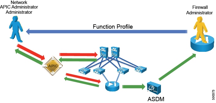
The ASA administrator provides the XML or JSON function profile configuration to the APIC administrator who then pushes the function profile through the APIC to the ASA device.
Translation of ASA Terminology
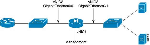
The following table translates which vNIC corresponds to which interface in Cisco ASAv and Cisco Application Centric Infrastructure (ACI):
|
Interface |
VMware |
ASAv |
ACI |
IP address is entered as |
|---|---|---|---|---|
|
Management |
vNIC1 |
Management |
N/A |
N/A |
|
Outside |
vNIC2 |
GigabitEthernet0/0 |
GigabitEthernet0/0 |
ExternalIf |
|
Inside |
vNIC3 |
GigabitEthernet0/1 |
GigabitEthernet0/1 |
InternalIf |
The following figure illustrates the naming convention for the interfaces in the case of a Cisco ASAv firewall:
About ASA Multi-Context Mode
You can partition a single physical ASA into multiple virtual firewalls, known as security/virtual contexts. Each context acts as an independent device with its own security policy, interfaces, and management IP address. You can use ASA multi-context capability in Cisco Application Centric Infrastructure (ACI) along with an ASA service graph. This configuration is supported with an ASA 5500-X device and ASA device package 1.2 or later.
ASA supports multi-context by adding individual ASA contexts as Cdev objects under the Layer 4 to Layer 7 devices. The Layer 4 to Layer 7 parameter configuration is pushed to individual ASA contexts, not to the "Admin" context. ACI pushes the "allocate-interface" configuration to the "Admin" context for the other contexts. This means that the IP address of the "Admin" context must be entered as the management IP address for the logical device configuration.
About ASA High Availability and Scalability
Failover provides simple device-level redundancy. Failover peers are adjacent on data interfaces and have the same active IP address or MAC address. An active/standby failover pair can be initially configured and managed through the Application Policy Infrastructure Controller (APIC). You must first register both ASAs with the APIC. Active/active failover not supported.
The ASA cluster must be deployed out of band, but the APIC can manage the cluster once it is deployed.
ASA in GoTo Mode
About Deploying ASA in GoTo Mode
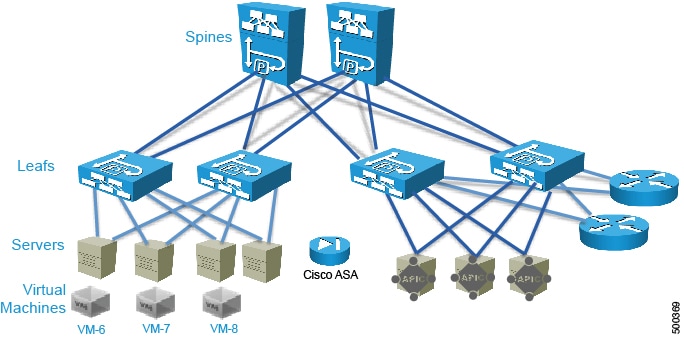
The following figure illustrates the topology for deploying Cisco Application Centric Infrastructure (ACI) fabric with ASA devices:
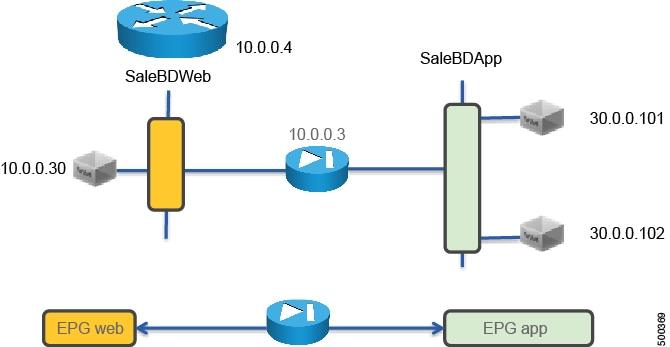
The following figure illustrates the logical topology of an ASA GoTo deployment:
To deploy an ASA device in the GoTo mode, you must do the following things:
-
Configure 2 bridge domains
-
Configure 2 endpoint groups with each one associated with a different bridge domain
-
Configure the ASA device as a GoTo device
-
Set up NAT with a public IP on the same subnet as the bridge domain that ASA connects to on the outside (or consumer side)
-
Configure the contract between the outside and inside endpoint group (or server side or provider side)
-
Associate the service graph with the contract
-
Associate the external logical interface with GigabitEthernet0/0 (which in the case of ASAv is Network Adapter 2)
-
Associate the internal logical interface with GigabitEthernet0/1 (which in the case of ASAv is Network Adapter 3)
Overview of Preparing an ASA Device in GoTo Mode
ASA and ASAv do not have the concept of VRF management. If ASA or ASAv are deployed in GoTo mode you might want to use "inband" management to ASA to avoid conflicting entries in the routing table. If you are using the service device in transparent mode, you do not need to use "inband" management because there is no need for VRF management.
The following procedure provides of overview of preparing an ASA device to be deployed in GoTo mode.
Configuring Bridge Domains for ASA in GoTo Mode
When you configure the bridge domains for ASA in GoTo mode, configure the bridge domains as you would for a generic configuration, except as follows:
-
L2 Unknown Unicast radio buttons—Choose Flood.
-
ARP Flooding check box—Put a check in the check box.
-
Unicast Routing check box—Put a check in the check box if you need to configure an L3Out or for the endpoint attach feature.
For information on how to configure bridge domains, see Creating Bridge Domains and VRFs Using the GUI.
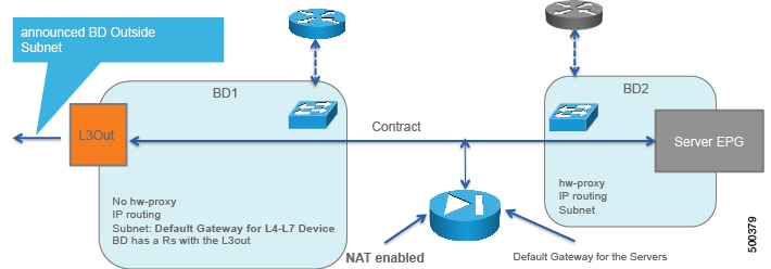
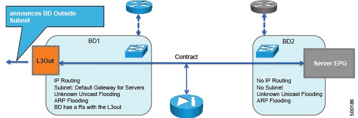
The following figure illustrates the bridge domain configuration for ASA in GoTo mode:
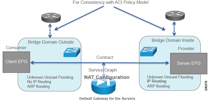
If you need the mapping database, such as for using traceroute or endpoint attach, you must enable unicast routing in the bridge domains.
Tuning the Server-Side Bridge Domain for Flood Removal for ASA in GoTo Mode
In GoTo mode you might want to optimize flooding. This tuning is meaningful only in the case of a service graph with GoTo mode, because in GoThrough mode Cisco Application Centric Infrastructure (ACI) sets the bridge domains to unknown unicast flooding.
On the server-side bridge domain, it can be beneficial to reduce flooding for unknown unicast packets. To do this, you can enable hardware proxy on the bridge domain. You should keep ARP flooding enabled because it might be necessary in the presence of ASA deployed in HA pairs.
Adding Endpoint Attach Support for ASA in GoTo Mode
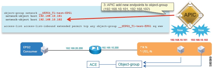
You can deploy an ASA device in a service graph in a way that the endpoints that are discovered in the provider endpoint group are automatically added to an object group. In the ASA device, this feature is called "endpoint attach".
The object group is given a name in the following format:
tenant_name-application_profile_name-EPG_name
For example:
ciscoasa# show run object-group
object-group network __$EPG$_T1-test-EPG1
  network-object host 192.168.10.100
The ACL will then reference this object group. The endpoint group detects the endpoint and populates the ACL. The Application Policy Infrastructure Controller (APIC) dynamically detects the new endpoint, then the endpoint is automatically added to the object group for ACE.
The following procedure enables endpoint attach.
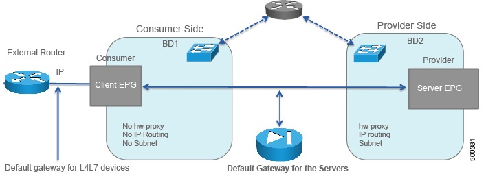
ASA GoTo Mode Design Examples
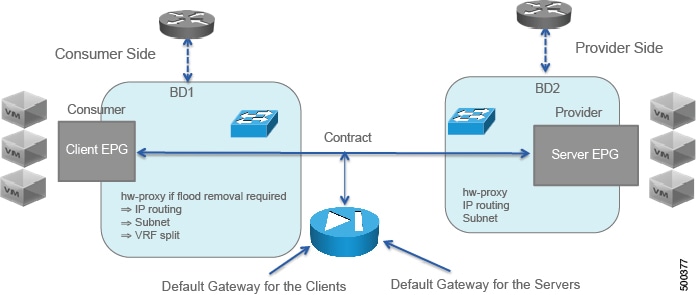
The following figures illustrate ASA GoTo mode deployments with various scenarios: some with the client connected directly to the fabric, some with the fabric providing routing to the outside, and some with an external router. The figures include the recommended bridge domain settings for both client and server-side bridge domains.
The settings for the server-side or provider-side (also known as the internal bridge domain, BD2) include IP routing in case you decide to use the endpoint attach feature. If you do not want to use endpoint attach and you do not care about flood reduction in the server-side bridge domain, you can configure the bridge domain without IP routing.
Deploying ASA in GoTo Mode
The tasks that you must perform to deploy ASA in GoTo mode are nearly identical to the tasks for generically deploying a service graph, with a few differences. The following procedure provides the generic service graph deployment tasks, along with information about what you must do differently to deploy ASA in GoTo mode.
| Step 1 | Import the device package. |
| Step 2 | Create the bridge domains and VRFs.
See Creating Bridge Domains and VRFs Using the GUI.
|
| Step 3 | Create endpoint groups and contracts. |
| Step 4 | Configure logical devices and concrete devices.
See Creating a Logical or Concrete Device Using the GUI.
If you have not yet applied the service graph template, a concrete device will have a health score of 0. This indicates the vNICs are not yet connected to a valid port group, which is normal since the graph has not been applied yet. As long as the device has a Device State of stable, then the communication between Application Policy Infrastructure Controller (APIC) and the device is working. |
| Step 5 | Create or import a function profile.
See Creating a Function Profile Using the GUI or Importing a Function Profile Using the GUI.
The following table describes the mandatory Layer 4 to Layer 7 parameters and provides examples of possible values that you must change for your specific configuration: The following XML illustrates an example of Layer 4 to Layer 7 parameters configuration for the ASA deployment in GoTo mode: <!-- RELATION TO THE EXTERNAL AND INTERNAL INTERFACES -->
<vnsFolderInst ctrctNameOrLbl="webtoapp" graphNameOrLbl="FW-routed" key="ExIntfConfigRelFolder" name="ExtConfig" nodeNameOrLbl="ASA-1-node" >
<vnsCfgRelInst key="ExIntfConfigRel" name="ExtConfigrel" targetName="externalIf"/>
</vnsFolderInst>
<vnsFolderInst ctrctNameOrLbl="webtoapp" graphNameOrLbl="FW-routed" key="InIntfConfigRelFolder" name="IntConfig" nodeNameOrLbl="ASA-1-node" >
<vnsCfgRelInst key="InIntfConfigRel" name="InConfigrel" targetName="internalIf"/>
</vnsFolderInst>
<!-- ACL DEFINITION, ACL NAME "access-list-inbound" -->
<vnsFolderInst ctrctNameOrLbl="webtoapp" graphNameOrLbl="FW-routed" key="AccessList" name="access-list-inbound" nodeNameOrLbl="ASA-1-node" >
<!-- ACE "permit-ssh" -->
<vnsFolderInst ctrctNameOrLbl="webtoapp" graphNameOrLbl="FW-routed" key="AccessControlEntry" name="permit-ssh" nodeNameOrLbl="ASA-1-node" >
<vnsParamInst key="order" name="order1" value="10"/>
<!-- protocol -->
<vnsFolderInst ctrctNameOrLbl="webtoapp" graphNameOrLbl="FW-routed" key="protocol" name="tcp" nodeNameOrLbl="ASA-1-node" >
<vnsParamInst key="name_number" name="tcp" value="tcp"/>
</vnsFolderInst>
<!-- source address -->
<vnsFolderInst ctrctNameOrLbl="webtoapp" graphNameOrLbl="FW-routed" key="source_address" name="src-address" nodeNameOrLbl="ASA-1-node" >
<vnsParamInst key="any" name="any" value="any"/>
</vnsFolderInst>
<!-- destination address -->
<vnsFolderInst ctrctNameOrLbl="webtoapp" graphNameOrLbl="FW-routed" key="destination_address" name="dest-address" nodeNameOrLbl="ASA-1-node" >
<vnsParamInst key="any" name="any" value="any"/>
</vnsFolderInst>
<!-- destination L4 port -->
<vnsFolderInst ctrctNameOrLbl="webtoapp" graphNameOrLbl="FW-routed" key="destination_service" name="dest-service" nodeNameOrLbl="ASA-1-node" >
<vnsParamInst key="operator" name="op" value="eq"/>
<vnsParamInst key="low_port" name="port" value="22"/>
</vnsFolderInst>
<!-- action permit or deny -->
<vnsParamInst key="action" name="action-permit" value="permit"/>
</vnsFolderInst>
<!-- ACE "permit-icmp" -->
<vnsFolderInst ctrctNameOrLbl="webtoapp" graphNameOrLbl="FW-routed" key="AccessControlEntry" name="permit-icmp" nodeNameOrLbl="ASA-1-node" >
<vnsParamInst key="order" name="order1" value="10"/>
<!-- protocol -->
<vnsFolderInst ctrctNameOrLbl="webtoapp" graphNameOrLbl="FW-routed" key="protocol" name="icmp" nodeNameOrLbl="ASA-1-node" >
<vnsParamInst key="name_number" name="icmp" value="icmp"/>
</vnsFolderInst>
<!-- source address -->
<vnsFolderInst ctrctNameOrLbl="webtoapp" graphNameOrLbl="FW-routed" key="source_address" name="src-address" nodeNameOrLbl="ASA-1-node" >
<vnsParamInst key="any" name="any" value="any"/>
</vnsFolderInst>
<!-- destination address -->
<vnsFolderInst ctrctNameOrLbl="webtoapp" graphNameOrLbl="FW-routed" key="destination_address" name="dest-address" nodeNameOrLbl="ASA-1-node" >
<vnsParamInst key="any" name="any" value="any"/>
</vnsFolderInst>
<!-- action -->
<vnsParamInst key="action" name="action-permit" value="permit"/>
</vnsFolderInst>
</vnsFolderInst>
<!-- EXTERNAL INTERFACE -->
<vnsFolderInst ctrctNameOrLbl="webtoapp" graphNameOrLbl="FW-routed" key="Interface" name="externalIf" nodeNameOrLbl="ASA-1-node" >
<vnsFolderInst ctrctNameOrLbl="webtoapp" graphNameOrLbl="FW-routed" key="InterfaceConfig" name="externalIfCfg" nodeNameOrLbl="ASA-1-node" >
<!-- security level -->
<vnsParamInst key="security_level" name="external_security_level" value="50"/>
<!-- IP ADDRESS-->
<vnsFolderInst ctrctNameOrLbl="webtoapp" graphNameOrLbl="FW-routed" key="IPv4Address" name="IPv4Address" nodeNameOrLbl="ASA-1-node" >
<vnsParamInst key="ipv4_address" name="ipv4_address" value="10.0.0.3/255.255.255.0"/>
</vnsFolderInst>
</vnsFolderInst>
<!-- access-group -->
<vnsFolderInst ctrctNameOrLbl="webtoapp" graphNameOrLbl="FW-routed" key="AccessGroup" name="ExtAccessGroup" nodeNameOrLbl="ASA-1-node" >
<vnsCfgRelInst key="inbound_access_list_name" name="name" targetName="access-list-inbound"/>
</vnsFolderInst>
</vnsFolderInst>
<vnsFolderInst ctrctNameOrLbl="webtoapp" graphNameOrLbl="FW-routed" key="Interface" name="internalIf" nodeNameOrLbl="ASA-1-node" >
<vnsFolderInst ctrctNameOrLbl="webtoapp" graphNameOrLbl="FW-routed" key="InterfaceConfig" name="internalIfCfg" nodeNameOrLbl="ASA-1-node" >
<!-- security level -->
<vnsParamInst key="security_level" name="internal_security_level" value="100"/>
<!-- IP ADDRESS-->
<vnsFolderInst ctrctNameOrLbl="webtoapp" graphNameOrLbl="FW-routed" key="IPv4Address" name="IPv4Address" nodeNameOrLbl="ASA-1-node" >
<vnsParamInst key="ipv4_address" name="ipv4_address" value="30.0.0.3/255.255.255.0"/>
</vnsFolderInst>
</vnsFolderInst>
</vnsFolderInst>
|
| Step 6 | Create a service graph template and either use a function profile or enter the
Layer 4 to Layer 7 parameters by hand.
See Creating a Layer 4 to Layer 7 Service Graph Template Using the GUI.
|
| Step 7 | Apply the service graph template.
See Applying a Service Graph Template to Endpoint Groups Using the GUI. |
| Step 8 | Verify that the configuration deployed successfully. |
ASA in GoThrough Mode
About Deploying ASA in GoThrough Mode
The following figure illustrates the topology for deploying Cisco Application Centric Infrastructure (ACI) fabric with ASA devices:
The following figure illustrates the logical topology of an ASA GoThrough deployment:

To deploy an ASA device in the GoThrough mode, you must do the following things:
-
Configure 2 bridge domains
-
Configure 2 endpoint groups with each one associated with a different bridge domain
-
Enable routing on only one of the two bridge domains, which normally would be the outside bridge domain for the purpose of an L3Out
-
Enable ARP flooding and unknown unicast flooding on both bridge domains
-
Configure the ASA device as a GoThrough device
-
Configure the contract between the outside and inside endpoint group (or server side or provider side)
-
Associate the service graph with the contract
-
Associate the external logical interface with GigabitEthernet0/0 (which in the case of ASAv is Network Adapter 2)
-
Associate the internal logical interface with GigabitEthernet0/1 (which in the case of ASAv is Network Adapter 3)
Overview of Preparing an ASA Device in GoThrough Mode
ASA and ASAv do not have the concept of VRF management. For GoThrough mode, you do not need to use "inband" management because there is no need for VRF management.
The following procedure provides of overview of preparing an ASA device to be deployed in GoThrough mode.
Configuring Bridge Domains for ASA in GoThrough Mode
While you can optimize the bridge domain settings for GoThrough mode and optimize flooding, in practice the GoThrough service graph modifies the bridge domains to enable unknown unicast flooding and ARP flooding. ARP flooding is needed to make sure that if a firewall changes its MAC address while keeping the same IP address as a result of a failover, the gratuitous ARP can reach all the servers in the bridge domain to get updated to point to the new MAC address. With ARP flooding enabled, hypothetically unknown unicast flooding would not be needed, but it is assumed that the firewall relies on flooding to discover where each MAC address is and to build the forwarding table.
IP routing can be enabled on both bridge domains if each bridge domain had a different VRF. However, the service graph for GoThrough mode changes the bridge domain settings and does not render if both bridge domains have IP routing enabled.
When you configure the bridge domains for ASA in GoThrough mode, configure the bridge domains as you would for a generic configuration, except as follows:
-
L2 Unknown Unicast radio buttons—Choose Flood.
-
ARP Flooding check box—Put a check in the check box.
-
Unicast Routing check box—Put a check in the check box.
-
Unicast Routing check box—Put a check in the check box if you are configuring the outside bridge domain and the Cisco Application Centric Infrastructure (ACI) fabric is the default gateway for the servers.
The GoThrough mode service graph does not render if IP routing is enabled on both bridge domains, and endpoint attach is not designed to work with GoThrough mode.
For information on how to configure bridge domains, see Creating Bridge Domains and VRFs Using the GUI.
The following figure illustrates the simplest bridge domain configuration for ASA in GoThrough mode:
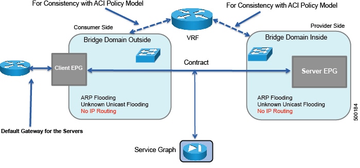
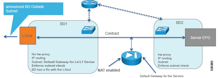
The following figure illustrates the bridge domain configuration for ASA deployment in GoThrough mode with an external router:
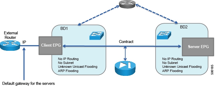
The following figure illustrates the bridge domain configuration for ASA deployment in GoThrough mode with an L3Out:
Deploying ASA in GoThrough Mode
The tasks that you must perform to deploy ASA in GoThrough mode are nearly identical to the tasks for generically deploying a service graph, with a few differences. The following procedure provides the generic service graph deployment tasks, along with information about what you must do differently to deploy ASA in GoThrough mode.
| Step 1 | Import the device package. | ||||||||||||||||||||||||||
| Step 2 | Create the bridge domains and VRFs.
See Creating Bridge Domains and VRFs Using the GUI.
| ||||||||||||||||||||||||||
| Step 3 | Create endpoint groups and contracts. | ||||||||||||||||||||||||||
| Step 4 | Configure logical devices and concrete devices.
See Creating a Logical or Concrete Device Using the GUI.
If you have not yet applied the service graph template, a concrete device will have a health score of 0. This indicates the vNICs are not yet connected to a valid port group, which is normal since the graph has not been applied yet. As long as the device has a Device State of stable, then the communication between Application Policy Infrastructure Controller (APIC) and the device is working. | ||||||||||||||||||||||||||
| Step 5 | Create or import a function profile.
See Creating a Function Profile Using the GUI or Importing a Function Profile Using the GUI.
The following table describes the mandatory Layer 4 to Layer 7 parameters and provides examples of possible values that you must change for your specific configuration:
The following XML is an example of a Layer 4 to Layer 7 parameters configuration: <!-- RELATION TO THE EXTERNAL AND INTERNAL INTERFACES -->
<vnsFolderInst ctrctNameOrLbl="webtoapp" graphNameOrLbl="FW-bridged" key="ExIntfConfigRelFolder" name="ExtConfig" nodeNameOrLbl="ASA-1-node" >
<vnsCfgRelInst key="ExIntfConfigRel" name="ExtConfigrel" targetName="externalIf"/>
</vnsFolderInst>
<vnsFolderInst ctrctNameOrLbl="webtoapp" graphNameOrLbl="FW-bridged" key="InIntfConfigRelFolder" name="IntConfig" nodeNameOrLbl="ASA-1-node" >
<vnsCfgRelInst key="InIntfConfigRel" name="InConfigrel" targetName="internalIf"/>
</vnsFolderInst>
<!-- ACL DEFINITION, ACL NAME "access-list-inbound" -->
<vnsFolderInst ctrctNameOrLbl="webtoapp" graphNameOrLbl="FW-bridged" key="AccessList" name="access-list-inbound" nodeNameOrLbl="ASA-1-node" >
<!-- ACE "permit-ssh" -->
<vnsFolderInst ctrctNameOrLbl="webtoapp" graphNameOrLbl="FW-bridged" key="AccessControlEntry" name="permit-ssh" nodeNameOrLbl="ASA-1-node" >
<vnsParamInst key="order" name="order1" value="10"/>
<!-- protocol -->
<vnsFolderInst ctrctNameOrLbl="webtoapp" graphNameOrLbl="FW-bridged" key="protocol" name="tcp" nodeNameOrLbl="ASA-1-node" >
<vnsParamInst key="name_number" name="tcp" value="tcp"/>
</vnsFolderInst>
<!-- source address -->
<vnsFolderInst ctrctNameOrLbl="webtoapp" graphNameOrLbl="FW-bridged" key="source_address" name="src-address" nodeNameOrLbl="ASA-1-node" >
<vnsParamInst key="any" name="any" value="any"/>
</vnsFolderInst>
<!-- destination address -->
<vnsFolderInst ctrctNameOrLbl="webtoapp" graphNameOrLbl="FW-bridged" key="destination_address" name="dest-address" nodeNameOrLbl="ASA-1-node" >
<vnsParamInst key="any" name="any" value="any"/>
</vnsFolderInst>
<!-- destination L4 port -->
<vnsFolderInst ctrctNameOrLbl="webtoapp" graphNameOrLbl="FW-bridged" key="destination_service" name="dest-service" nodeNameOrLbl="ASA-1-node" >
<vnsParamInst key="operator" name="op" value="eq"/>
<vnsParamInst key="low_port" name="port" value="22"/>
</vnsFolderInst>
<!-- action permit or deny -->
<vnsParamInst key="action" name="action-permit" value="permit"/>
</vnsFolderInst>
<!-- ACE "permit-icmp" -->
<vnsFolderInst ctrctNameOrLbl="webtoapp" graphNameOrLbl="FW-bridged" key="AccessControlEntry" name="permit-icmp" nodeNameOrLbl="ASA-1-node" >
<vnsParamInst key="order" name="order1" value="10"/>
<!-- protocol -->
<vnsFolderInst ctrctNameOrLbl="webtoapp" graphNameOrLbl="FW-bridged" key="protocol" name="icmp" nodeNameOrLbl="ASA-1-node" >
<vnsParamInst key="name_number" name="icmp" value="icmp"/>
</vnsFolderInst>
<!-- source address -->
<vnsFolderInst ctrctNameOrLbl="webtoapp" graphNameOrLbl="FW-bridged" key="source_address" name="src-address" nodeNameOrLbl="ASA-1-node" >
<vnsParamInst key="any" name="any" value="any"/>
</vnsFolderInst>
<!-- destination address -->
<vnsFolderInst ctrctNameOrLbl="webtoapp" graphNameOrLbl="FW-bridged" key="destination_address" name="dest-address" nodeNameOrLbl="ASA-1-node" >
<vnsParamInst key="any" name="any" value="any"/>
</vnsFolderInst>
<!-- action -->
<vnsParamInst key="action" name="action-permit" value="permit"/>
</vnsFolderInst>
</vnsFolderInst>
<!-- BRIDGE-GROUP 1 -->
<vnsFolderInst ctrctNameOrLbl="webtoapp" graphNameOrLbl="FW-bridged" key="BridgeGroupIntf" name="1" nodeNameOrLbl="ASA-1-node" scopedBy="epg">
<vnsParamInst key="ipv6_nd_dad_attempts" name="ipv6_nd_dad_attempts" validation="" value="1"/>
<!-- IP ADDRESS-->
<vnsFolderInst ctrctNameOrLbl="webtoapp" graphNameOrLbl="FW-bridged" key="IPv4Address" name="IPv4Address" nodeNameOrLbl="ASA-1-node" scopedBy="epg">
<vnsParamInst key="ipv4_address" name="ipv4_address" validation="" value="30.0.0.254/255.255.255.0"/>
</vnsFolderInst>
</vnsFolderInst>
<!-- EXTERNAL INTERFACE -->
<vnsFolderInst ctrctNameOrLbl="webtoapp" graphNameOrLbl="FW-bridged" key="Interface" name="externalIf" nodeNameOrLbl="ASA-1-node" >
<vnsFolderInst ctrctNameOrLbl="webtoapp" graphNameOrLbl="FW-bridged" key="InterfaceConfig" name="externalIfCfg" nodeNameOrLbl="ASA-1-node" >
<!-- BRIDGE-GROUP CONFIGURATION -->
<vnsCfgRelInst key="bridge_group" name="extbridge" targetName="1"/>
<!-- security level -->
<vnsParamInst key="security_level" name="external_security_level" value="50"/>
</vnsFolderInst>
<!-- access-group -->
<vnsFolderInst ctrctNameOrLbl="webtoapp" graphNameOrLbl="FW-bridged" key="AccessGroup" name="ExtAccessGroup" nodeNameOrLbl="ASA-1-node" >
<vnsCfgRelInst key="inbound_access_list_name" name="name" targetName="access-list-inbound"/>
</vnsFolderInst>
</vnsFolderInst>
<vnsFolderInst ctrctNameOrLbl="webtoapp" graphNameOrLbl="FW-bridged" key="Interface" name="internalIf" nodeNameOrLbl="ASA-1-node" >
<vnsFolderInst ctrctNameOrLbl="webtoapp" graphNameOrLbl="FW-bridged" key="InterfaceConfig" name="internalIfCfg" nodeNameOrLbl="ASA-1-node" >
<!-- BRIDGE-GROUP CONFIGURATION -->
<vnsCfgRelInst key="bridge_group" name="intbridge" targetName="1"/>
<!-- security level -->
<vnsParamInst key="security_level" name="internal_security_level" value="100"/>
</vnsFolderInst>
</vnsFolderInst>
| ||||||||||||||||||||||||||
| Step 6 | Create a service graph template and either use a function profile or enter the
Layer 4 to Layer 7 parameters by hand.
See Creating a Layer 4 to Layer 7 Service Graph Template Using the GUI.
| ||||||||||||||||||||||||||
| Step 7 | Apply the service graph template.
See Applying a Service Graph Template to Endpoint Groups Using the GUI. You cannot configure an "any" virtual IP or port. You can only choose TCP or UDP option; there is no "all IP protocol" value. | ||||||||||||||||||||||||||
| Step 8 | Verify that the configuration deployed successfully. |
Verifying the Configuration for an ASA Device
After you deployed an ASA device in any mode, you can verify that the configuration is functioning properly by using the following procedure. If you encounter an issue, you can try troubleshooting by viewing the Application Policy Infrastructure Controller (APIC) log that is at the following location:
/data/devicescript/CISCO.ASA.1.2/logs/debug.log
Undoing a Service Graph Configuration for ASA
To undo a service graph configuration for ASA, in the Application Policy Infrastructure Controller (APIC) GUI, delete the service graph template.
 Feedback