Cisco APIC Layer 4 to Layer 7 Service Graph Deployment Guide, Release 1.2(2g)
Bias-Free Language
The documentation set for this product strives to use bias-free language. For the purposes of this documentation set, bias-free is defined as language that does not imply discrimination based on age, disability, gender, racial identity, ethnic identity, sexual orientation, socioeconomic status, and intersectionality. Exceptions may be present in the documentation due to language that is hardcoded in the user interfaces of the product software, language used based on RFP documentation, or language that is used by a referenced third-party product. Learn more about how Cisco is using Inclusive Language.
- Updated:
- April 20, 2016
Chapter: Route Peering
Route Peering
- About Route Peering
- Configuring Route Peering Using the GUI
- Verifying a Route Peering With a Static Route Configuration Using the GUI
- Verifying a Route Peering With OSPF Configuration Using the GUI
About Route Peering
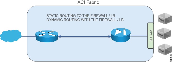
Route peering is a special case of the more generic Cisco Application Centric Infrastructure (ACI) fabric as a transit use case, in which route peering enables the ACI fabric to serve as a transit domain for Open Shortest Path First (OSPF) or Border Gateway Protocol (BGP) protocols. A common use case for route peering is route health injection, in which the server load balancing virtual IP is advertised over OSPF or internal BGP (iBGP) to clients that are outside of the ACI fabric. You can use route peering to configure OSPF or BGP peering on a service device so that the device can peer and exchange routes with the ACI leaf node to which it is connected.
The goal for using route peering is to configure static routing to the firewall or load balancer and to use dynamic routing with the firewall or load balancer, as shown in the following figure:
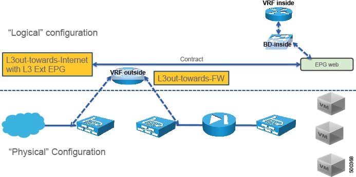
Route peering requires 2 L3Outs, as shown in the following figure:
If you deploy route peering with a virtual appliance, you must specify the exact physical interface to which the virtual appliance is connected.
For more information about route peering, see Cisco APIC Layer 4 to Layer 7 Services Deployment Guide .
Configuring Route Peering Using the GUI
The following procedure provides an example on how to configure route peering using an ASA device that is part of a two-node service graph. The other service device in the service graph is an F5 BIG-IP device.
This example provides values for most of the fields; the values for your setup will vary. You must fill out mandatory fields even if no example values are given in this procedure. This example uses T1 as the name of the Tenant.
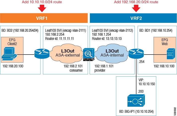
The following figure illustrates the components that you must configure to use route peering.
| Step 1 | Create three bridge domains and two VRFs. This procedure uses BD1, BD2, and BIG-IP1 as the bridge domains, and VRF1 and VRF2 as the VRFs. | ||||||||||||||||||||||||||||||||||||||||||||||||||||||||
| Step 2 | On the menu bar, choose . | ||||||||||||||||||||||||||||||||||||||||||||||||||||||||
| Step 3 | In the Work pane, double click the tenant's name. | ||||||||||||||||||||||||||||||||||||||||||||||||||||||||
| Step 4 | In the
Navigation pane, choose
.
Choose the contract that you will associate with VRF2. | ||||||||||||||||||||||||||||||||||||||||||||||||||||||||
| Step 5 | In the Work pane, choose the Policy tab. | ||||||||||||||||||||||||||||||||||||||||||||||||||||||||
| Step 6 | In the Scope drop-down list, if the provider endpoint group and consumer endpoint group are in different tenants, choose Global. Otherwise, choose Tenant. | ||||||||||||||||||||||||||||||||||||||||||||||||||||||||
| Step 7 | Click Submit. | ||||||||||||||||||||||||||||||||||||||||||||||||||||||||
| Step 8 | Create an L3Out domain for ASA. On the menu bar, choose . | ||||||||||||||||||||||||||||||||||||||||||||||||||||||||
| Step 9 | In the Navigation pane, choose . | ||||||||||||||||||||||||||||||||||||||||||||||||||||||||
| Step 10 | In the Work pane, choose . | ||||||||||||||||||||||||||||||||||||||||||||||||||||||||
| Step 11 | In the Create Layer 3 Domain dialog box, fill in the fields as required, except as specified below: | ||||||||||||||||||||||||||||||||||||||||||||||||||||||||
| Step 12 | In the Create VLAN Pool dialog box, fill in the fields as required, except as specified below: | ||||||||||||||||||||||||||||||||||||||||||||||||||||||||
| Step 13 | Click Submit. | ||||||||||||||||||||||||||||||||||||||||||||||||||||||||
| Step 14 | In the Create Layer 3 Domain dialog box, click Submit. | ||||||||||||||||||||||||||||||||||||||||||||||||||||||||
| Step 15 | In the Work pane, verify that L3_ASA was created. | ||||||||||||||||||||||||||||||||||||||||||||||||||||||||
| Step 16 | Create an external routed network with
either a static route or OSPF.
To create an external routed network with a static route, see Configuring an External Routed Network for Route Peering with a Static Route Using the GUI. To create an external routed network with OSPF, see Configuring an External Routed Network for Route Peering with OSPF Using the GUI. In either case, use the values for the first external routed network. | ||||||||||||||||||||||||||||||||||||||||||||||||||||||||
| Step 17 | Create a second external routed network
using the same protocol as the previous step.
To create an external routed network with a static route, see Configuring an External Routed Network for Route Peering with a Static Route Using the GUI. To create an external routed network with OSPF, see Configuring an External Routed Network for Route Peering with OSPF Using the GUI. In either case, use the values for the second external routed network. | ||||||||||||||||||||||||||||||||||||||||||||||||||||||||
| Step 18 | Create an ASA function profile in the
Common tenant.
See Creating a Function Profile Using the GUI. The following differences in the steps are specific to route peering. In the Create Routed Outside dialog box:
| ||||||||||||||||||||||||||||||||||||||||||||||||||||||||
| Step 19 | Create a BIG-IP function profile in the
Common tenant.
See Creating a Function Profile Using the GUI. The following differences in the steps are specific to this scenario.
| ||||||||||||||||||||||||||||||||||||||||||||||||||||||||
| Step 20 | Create a
service graph template.
See Creating a Layer 4 to Layer 7 Service Graph Template Using the GUI. The following differences in the steps are specific to route peering. In the Create L4-L7 Service Graph Template dialog box:
| ||||||||||||||||||||||||||||||||||||||||||||||||||||||||
| Step 21 | (Optional)In the
Navigation pane, choose
.
Choose the service graph template that you just created and the load balancer function node. | ||||||||||||||||||||||||||||||||||||||||||||||||||||||||
| Step 22 | Apply the
service graph template.
See Applying a Service Graph Template to Endpoint Groups Using the GUI. The following differences in the steps are specific to route peering. In the Apply L4-L7 Service Graph Template to EPGs dialog box:
|
Configuring an External Routed Network for Route Peering with a Static Route Using the GUI
You can configure an external routed network for use with route peering by using a static route. The external routed network specifies the routing configuration in the Cisco Application Centric Infrastructure (ACI) fabric.
You must configure two external routed networks, and as such the following procedure provides two different sets of values—one for each of the networks—where necessary.
Configuring an External Routed Network for Route Peering with OSPF Using the GUI
You can configure an external routed network for use with route peering by using OSPF. The external routed network specifies the routing configuration in the Cisco Application Centric Infrastructure (ACI) fabric.
You must configure two external routed networks, and as such the following procedure provides two different sets of values—one for each of the networks—where necessary.
Verifying a Route Peering With a Static Route Configuration Using the GUI
After configuring a setup to use route peering with a static route, you can verify the configuration with the following procedure.
| Step 1 | Verify the
service graph deployment.
See Verifying a Service Graph Deployment Using the GUI For the deployed devices, you should see ASA-5525X-L3-none and BIGIP-LTM-VRF2. For the ASA-5525X-L3 cluster interfaces, you should see ASA-5525X-L3_consumer and ASA-5525X-L3_provider[ |
| Step 2 | Using the
CLI on the leaf switch, verify that the IP routing table for
VRF1 is correct.
Leaf3# show ip route vrf T1:VRF1
...
10.10.10.0/24, ubest/mbest: 1/0
    *via 192.168.2.101, vlan15, [1/0], 17:29:50, static
11.11.11.11/32, ubest/mbest: 2/0, attached, direct
    *via 11.11.11.11, lo3, [1/0], 4d23h, local, local
    *via 11.11.11.11, lo3, [1/0], 4d23h, direct
192.168.2.0/24, ubest/mbest: 1/0, attached, direct
    *via 192.168.2.254, vlan15, [1/0], 17:29:50, direct
192.168.2.254/32, ubest/mbest: 1/0, attached
    *via 192.168.2.254, vlan15, [1/0], 17:29:50, local, local
192.168.20.0/24, ubest/mbest: 1/0, attached, direct, pervasive
    *via 10.0.80.64%overlay-1, [1/0], 01:53:21, static
The route peering IP route is shown in bold. |
| Step 3 | Verify that
the IP routing table for
VRF2 is correct.
Leaf3# show ip route vrf T1:VRF2
...
10.10.10.0/24, ubest/mbest: 1/0, attached, direct, pervasive
    *via 10.0.80.64%overlay-1, [1/0], 01:54:10, static
10.10.10.254/32, ubest/mbest: 1/0, attached
    *via 10.10.10.254, vlan17, [1/0], 01:54:10, local, local
192.168.1.0/24, ubest/mbest: 1/0, attached, direct
    *via 192.168.1.254, vlan16, [1/0], 02:08:12, direct
192.168.1.254/32, ubest/mbest: 1/0, attached
    *via 192.168.1.254, vlan16, [1/0], 02:08:12, local, local
192.168.10.0/24, ubest/mbest: 1/0, attached, direct, pervasive
    *via 10.0.80.64%overlay-1, [1/0], 01:54:10, static
192.168.20.0/24, ubest/mbest: 1/0
    *via 192.168.1.101, vlan16, [1/0], 02:08:12, static
The route peering IP route is shown in bold. |
| Step 4 | Verify that
the routing table is correct.
ASA5525X/T1# show route
...
S*    0.0.0.0 0.0.0.0 [1/0] via 172.16.255.254, management
S        10.10.10.0 255.255.255.0 [1/0] via 192.168.1.254, internalIf
C        172.16.0.0 255.255.0.0 is directly connected, management
L        172.16.0.101 255.255.255.255 is directly connected, management
C        192.168.1.0 255.255.255.0 is directly connected, internalIf
L        192.168.1.101 255.255.255.255 is directly connected, internalIf
C        192.168.2.0 255.255.255.0 is directly connected, externalIf
L        192.168.2.101 255.255.255.255 is directly connected, externalIf
S     192.168.20.0 255.255.255.0 [1/0] via 192.168.2.254, externalIf
The route peering routes are shown in bold. |
Verifying a Route Peering With OSPF Configuration Using the GUI
After configuring a setup to use route peering with OSPF, you can verify the configuration with the following procedure.
| Step 1 | Verify the service graph deployment.
See Verifying a Service Graph Deployment Using the GUI For the deployed devices, you should see ASA-5525X-L3-none and BIGIP-LTM-VRF2. For the ASA-5525X-L3 cluster interfaces, you should see ASA-5525X-L3_consumer and ASA-5525X-L3_provider[ |
| Step 2 | Using the CLI on the leaf switch, verify that the IP routing table for
VRF1 is correct.
Leaf3# show ip route vrf T1:VRF1
...
10.10.10.0/24, ubest/mbest: 1/0
    *via 192.168.2.101, vlan20, [110/20], 00:00:27, ospf-default, type-2, tag 200
11.11.11.11/32, ubest/mbest: 2/0, attached, direct
    *via 11.11.11.11, lo3, [1/0], 5d02h, local, local
    *via 11.11.11.11, lo3, [1/0], 5d02h, direct
192.168.1.0/24, ubest/mbest: 1/0
    *via 192.168.2.101, vlan20, [110/14], 00:15:51, ospf-default, intra
192.168.2.0/24, ubest/mbest: 1/0, attached, direct
    *via 192.168.2.254, vlan20, [1/0], 00:30:04, direct
192.168.2.254/32, ubest/mbest: 1/0, attached
    *via 192.168.2.254, vlan20, [1/0], 00:30:04, local, local
192.168.20.0/24, ubest/mbest: 1/0, attached, direct, pervasive
    *via 10.0.80.64%overlay-1, [1/0], 00:16:02, static
The route peering IP route is shown in bold. |
| Step 3 | Verify that the IP routing table for VRF2 is correct.
Leaf3# show ip route vrf T1:VRF2
...
10.10.10.0/24, ubest/mbest: 1/0, attached, direct, pervasive
    *via 10.0.80.64%overlay-1, [1/0], 00:16:05, static
10.10.10.254/32, ubest/mbest: 1/0, attached
    *via 10.10.10.254, vlan13, [1/0], 00:16:05, local, local
192.168.1.0/24, ubest/mbest: 1/0, attached, direct
    *via 192.168.1.254, vlan16, [1/0], 04:48:44, direct
192.168.1.254/32, ubest/mbest: 1/0, attached
    *via 192.168.1.254, vlan16, [1/0], 04:48:44, local, local
192.168.2.0/24, ubest/mbest: 1/0
    *via 192.168.1.101, vlan16, [110/14], 00:15:53, ospf-default, intra
192.168.10.0/24, ubest/mbest: 1/0, attached, direct, pervasive
    *via 10.0.80.64%overlay-1, [1/0], 00:01:52, static
192.168.20.0/24, ubest/mbest: 1/0
    *via 192.168.1.101, vlan16, [110/20], 00:01:48, ospf-default, type-2, tag 100
The route peering IP route is shown in bold. |
| Step 4 | Verify that the routing table is correct.
ASA5525X/T1# show route
...
S*    0.0.0.0 0.0.0.0 [1/0] via 172.16.255.254, management
O E2     10.10.10.0 255.255.255.0
           [110/20] via 192.168.1.254, 00:00:32, internalIf
C        172.16.0.0 255.255.0.0 is directly connected, management
L        172.16.0.101 255.255.255.255 is directly connected, management
C        192.168.1.0 255.255.255.0 is directly connected, internalIf
L        192.168.1.101 255.255.255.255 is directly connected, internalIf
C        192.168.2.0 255.255.255.0 is directly connected, externalIf
L        192.168.2.101 255.255.255.255 is directly connected, externalIf
O E2     192.168.20.0 255.255.255.0
           [110/20] via 192.168.2.254, 00:00:32, externalIf
The route peering routes are shown in bold. |
 Feedback