Cisco APIC Layer 4 to Layer 7 Device Package Development Guide, Release 1.1(1j)
Bias-Free Language
The documentation set for this product strives to use bias-free language. For the purposes of this documentation set, bias-free is defined as language that does not imply discrimination based on age, disability, gender, racial identity, ethnic identity, sexual orientation, socioeconomic status, and intersectionality. Exceptions may be present in the documentation due to language that is hardcoded in the user interfaces of the product software, language used based on RFP documentation, or language that is used by a referenced third-party product. Learn more about how Cisco is using Inclusive Language.
- Updated:
- June 3, 2015
Chapter: Fabric Connectivity
Fabric Connectivity
Registering Devices
-
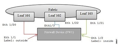
Topology information: How device interfaces are connected to the fabric leaf nodes.
-
Label interfaces: Based on the device requirements. The labels are used by the APIC to bind an interface with a connector for specific functions that are provided by the service device.
-
IP address and port information: Information that is needed to connect to the device.
-
Username and password: Credentials used for configuring the device.
The labels are defined in the device specification using the vnsMIfLbl tag. All interfaces on the firewall device are categorized into one of the types defined by the device specification.
 Note | The APIC does not check if the interface actually exists on the device. |
<polUni>
    <fvTenant
        dn="uni/tn-Tenant1"
        name="Tenant1">
        <vnsLDevVip name="Firewall-1">

            <vnsLIf name="external">
                <vnsRsMetaIf tDn="uni/infra/mDev-CISCO-ASA-1.0.1.16/mIfLbl-external"/>
                <vnsRsCIfAtt tDn="uni/tn-Tenant1/lDevVip-Firewall/cDev-ASA/cIf-Eth1_1"/>
            </vnsLIf>
            <vnsLIf name="internal">
                <vnsRsMetaIf tDn="uni/infra/mDev-CISCO-ASA-1.0.1.16/mIfLbl-internal"/>
                <vnsRsCIfAtt tDn="uni/tn-Tenant1/lDevVip-Firewall/cDev-ASA/cIf-Eth1_2"/>
            </vnsLIf>
            <vnsCDev name="FW1">

                <vnsCIf name="Eth1_1">
                       <vnsRsCIfPathAtt tDn="topology/pod-1/paths-101/pathep-[eth1/20]"/>
                </vnsCIf>
                <vnsCIf name="Eth1_2">
                       <vnsRsCIfPathAtt tDn="topology/pod-1/paths-102/pathep-[eth1/21]"/>
                </vnsCIf>
                <vnsCIf name="Eth1_3">
                       <vnsRsCIfPathAtt tDn="topology/pod-1/paths-103/pathep-[eth1/22]"/>
                </vnsCIf>

                <vnsCMgmt name="devMgmt"
                          host="192.168.78.62"
                          port="80"
                          />

               <vnsCCred name="username"
                          value="admin"
                          />
               <vnsCCredSecret name="password"
                          value="insieme"
                          />
            </vnsCDev>
        </vnsLDevVip>
    </fvTenant>
</polUni>
The following figure shows the topology of registering a device.
Connectors
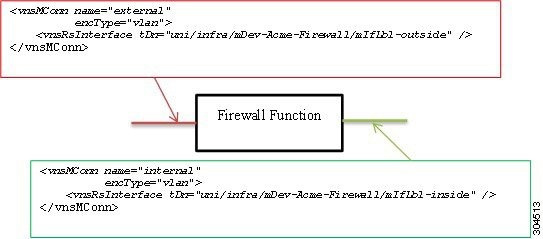
In the following figure, two connectors are associated to a firewall function. The first connector represents connectivity to an external or outside network, and the second connector represents connectivity to an internal or inside network on the firewall device. Both are tagged with a VLAN header.
Service Graphs
A service graph is an ordered set of functions between a set of terminals. You can manually create a service graph using the GUI or CLI, or create one programmatically using the Application Policy Infrastructure Controller (APIC) Northbound Service Integration API. A function within the graph might require one or more parameters and have one or more connectors.
A service graph represents the network using the following elements:
-
Function Nodes (green)—A function applied to traffic such as a transform (SSL termination, VPN gateway), filter (firewalls), or terminal (intrusion detection systems)
-
Terminal Nodes (blue)—Input and outputs from the service graph
-
Connector (white)—Input and output from a node
-
Connections—How traffic is forwarded through the network
The following figure shows a service graph.
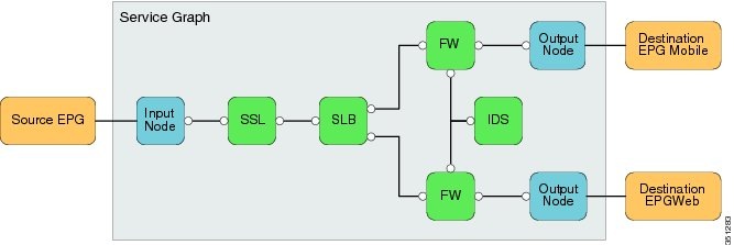
Note | Although this generic service graph shows two output nodes, the fabric supports only a single input node and a single output node from a service graph at this time. The serviceModify function is used to instantiate the network and function configurations. |
Graph Rendering
-
Assigns a VLAN/VXLAN ID for the connector. The APIC checks whether the previous node has been allocated a VLAN/VXLAN ID. It either uses the previous node value or allocates a new tag for the connector. The encType indicates whether the VLAN/VXLAN ID is allocated.
-
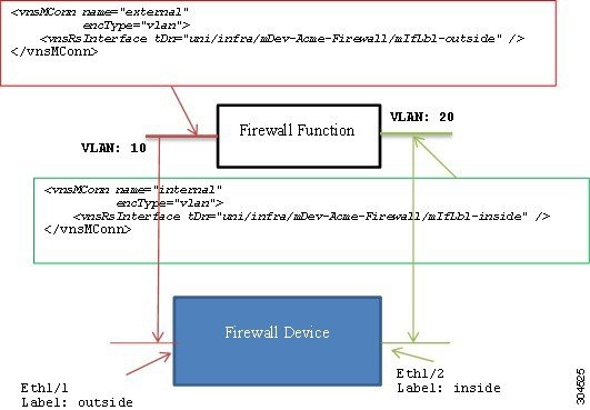
Uses interface relation and device interface label information to associate an interface to a connector. In the previous figure, rendering a firewall function on the firewall device will result in these bindings:
You should enable or bind the VLAN or VXLAN tags that are assigned to the connector to the associated interfaces.
In the following figure, the APIC assigns VLAN 10 to the outside connector and VLAN 20 to the inside connector. The device script must configure VLAN 10 on interface Eth1/1 and bind it to the firewall function. Similarly, the device script must configure VLAN 20 on interface Eth1/2 and bind it to the firewall function.
Device Script Interface
Configuration =
{
 (0, '', <LdevInstance>): {
   ...
   (7, '', <encap-instance>): {'state': 1, 'tag': TagValue, 'type': TagType},
   (7, '', <encap-instance>): {'state': 1, 'tag': TagValue, 'type': 0},
   (8, '', <encap-association-Instance>): {
         'state': 1,
         'encap': <encapInstance>,
         'vif': <LogicalInterfaceInstanceID>}
   },
   (8, '', <encap-association-Instance>): {
         'state': 1,
         'encap': <encapInstance>,
         'vif': <LogicalInterfaceInstanceID>},
   },
   (10, '', <LogicalInterfaceInstance>): {
         'state': 0,
         'cifs': {
            'cDevInstance': <Interface Value>
         }
   },
   (10, '', <LogicalInterfaceInstance>): {
         'state': 0,
         'cifs': {
            'cDevInstance': <Interface Value>
         }
   },
 }
}

Legend:
The dictionary format is as follows:

(type, key, name): {
   'state': StateValue,
   'device': CDevName,
   'connector': connectorValue,
   'value': Parameter Value,
}


type:
7 – Encap Instance [Encap Type=0 (VLAN), Encap Type=1 (VXLAN))]
                    Encap Tag = VLAN ID or VNID (VXLAN case)
8 – VEncapAss (Device Interface and Encap (VXLAN/VLAN) association)
10 – VIF (logical interface) – Identifies interface on the device.

CDevName: Identifies a specific device within a cluster node. This attribute is not applicable to encap, VIF, or vEncapAss.

connectorValue: Identifies the connector to which this parameter should be bound. This attribute is not applicable to encap, VIF, or vEncapAss.

value: Value of the parameter.

StateValue:
0 – No change
1 – Create
2 – Modify
3 - Destroy
Configuration =
{
    (0, '', 'Firewall-1'): {
      'state': 2,
      'value': {
         (7, '', '1553'): {'state': 1, 'tag': 10, 'type': 0},
         (7, '', '7697'): {'state': 1, 'tag': 20, 'type': 0},
         (8, '', 'Firewall-1_outside_1553'): {'state': 1,
                                              'encap': '1553',
                                              'vif': 'Firewall-1_outside'},
         (8, '', 'Firewall-1_inside_7697'): {'state': 1,
                                             'encap': '1553',
                                             'vif': 'Firewall-1_inside'},

         (10, '', 'Firewall-1_outside'): {'state': 1,
                                          'cifs': {'FW2': 'Eth1/1' }
                                         },
         (10, '', 'Firewall-1_inside'):  {'state': 1,
                                          'cifs': {'FW': 'Eth1/2'}}
                                         }
         (1, '', '4552'): {
            'state': 1,
            'value': {
              (3, 'Firewall', 'F1’): {
                  'state': 1,
                  'value': {
                      (2, 'external', 'conn1'): { 'state': 1,
                          'value': {
                             ('9', '', 'outside_1553'): {
                                  'state': 1,
                                  'value': 'Firewall-1-outside_1553'
                             },
                          }
                      },
                      (2, 'internal', 'conn2'): { 'state': 1
                          'value': {
                             ('9', '', 'inside_7697'): {
                                  'state': 1,
                                  'value': 'Firewall-1-inside_7697'
                             },
                          }
                      },
                      (4, 'Firewall-Config', 'FW-Config 1'): {
                           'state': 1,
                           'value' : {
                               (5, 'Param-1', ''): { 'state': 1, 'value': value },
                           . . .
                           }
                      },
                  },
              },
           },
         },
      },
}
Note | The connector value is a dictionary that allows each device within the cluster to use different interfaces. |
 Feedback