Cisco Lean Retail IBM WebSphere Portal Application Deployment Guide
Available Languages
Table Of Contents
Cisco Lean Retail IBM WebSphere Portal
Application Deployment GuideApplication and Application Networking Design
Packet Flow Without Cisco WAAS and Cisco ACE
Packet Flow with Cisco WAAS and Cisco ACE
Implementing and Configuring the Cisco ACE Solution
What Was Not Implemented/Tested
Features, Services, and Application Design Considerations
High Availability, Scalability, and Redundancy
Installing Cisco ACE and MSFC Configuration
Configuring Interface(s) and Default Gateway
Stickiness (Session Persistence)
Implementing and Configuring the Cisco WAAS Solution
Features, Services, and Application Design Considerations
Scalability and Capacity Planning
Appendix A—Cisco ACE Configuration
Appendix B—Cisco WAE Configurations
Data Center Cisco WAE Configuration
Appendix C—Implementing and Configuring the ACE Appliance Solution
What Was Not Implemented/Tested
Configuring the ACE Appliance to the Catalyst 6509 Configuration
WAAS and ACE Appliance Results
Cisco Services Help Accelerate and Optimize ANS Deployments
Cisco Lean Retail IBM WebSphere Portal
Application Deployment Guide
April 14, 2008
Introduction
The Cisco Lean Retail IBM WebSphere Portal solution provides best practices and implementation guidance that optimizes application availability, performance, and security while lowering application ownership costs. Cisco's Lean Retail Architecture provides accelerated application performance and improved access to information. Data center-based applications and hosted managed services can have their performance accelerated to LAN-like speeds. IBM's WebSphere Portal Version 6.0 greatly reduces administrative load, allows more flexible applications to be built, and enhances the user experience by aggregating applications and content as role-based applications.
Cisco's Lean Retail Architecture includes:
•
Application and collaboration services
•
•
A key Lean Retail integrated network service is the Application Networking Service (ANS). This solution focuses on the ANS components of Cisco Application Control Engine (Cisco ACE) and Wide Area Application Services (WAAS) product families. It provides data center, retail store, and remote end user application optimization services. This solution addresses the following IBM WebSphere Portal deployment challenges:
•
•
•
•
The value of Cisco's Lean Retail is accomplished through four key benefits:
•
•
•
•
Deploying new applications and capabilities quickly and effectively are key IT metrics that improve an organization's business agility. Cisco's Lean Retail enables more applications to be deployed centrally, cutting down dramatically on the time and cost of deployment. Deploying centrally also reduces the costs of opening new stores and of integrating acquisitions. While many retailers will choose to deploy some applications in the stores, Lean Retail Architecture improves the capabilities of a central deployment model. To learn more about Cisco's Lean Retail, see:
http://www.cisco.com/web/strategy/retail/lean-retail.html
Prerequisites
The following prerequisites are required to deploy the IBM WebSphere Solution:
•
•
•
•
Document Organization
The following table provides a brief description of each section.
A high-level introduction to the solution. Introduces the solution, historical aspects, potential benefits, and scope and limitations.
Describes the design of the Lean Retail WebSphere Solution.
Describes configuration and implementation of Cisco ACE within the Lean Retail WebSphere Solution.
Describes configuration and implementation of WAAS within the Lean Retail WebSphere Solution.
Sample Cisco ACE configuration.
Sample Cisco WAW configuration.
Appendix C—Implementing and Configuring the ACE Appliance Solution
Describes the configuration and implementation of Cisco ACE Applicance within the Lean Retail WebSphere Solution.
Describes the network management software used in the Lean Retail WebSphere Solution.
Lists references and describes the Cisco services available to accelerate deployment of the Lean Retail WebSphere Solution.
Solution Overview
Solution Description
The Lean Retail WebSphere Solution offers optimized WebSphere application availability, performance, security, and cost savings by providing application optimization services as follows:
•
Cisco ACE product family application optimization services for high WebSphere availability:
–
–
–
•
Cisco ACE and WAAS product family application optimization services for WebSphere high performance:
–
–
–
–
–
–
–
–
•
Cisco ACE product family application optimization services for optimized WebSphere data security:
–
–
•
Virtualization of application optimization services supplies such services for multiple WebSphere instances as well as other enterprise applications (see Figure 1). Specifically, a single physical Cisco ACE can be virtualized into multiple logical Cisco ACEs in which application traffic can traverse between virtualized Cisco ACEs. This virtualization of load balancing is an exclusive Cisco feature.
Figure 1 Virtualization of Application Optimization Services
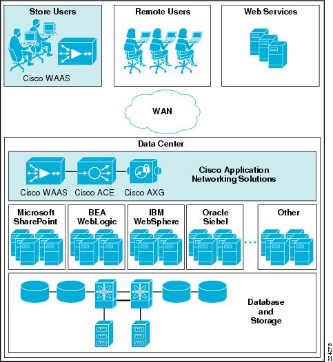
The application optimization services of the ANS WebSphere Solution reside in both the data center and the store to offer end-to-end value, from store and remote users, all the way through to the database and information storage.
•
Cisco ACE and WAAS reside in the data center and are arranged to provide virtualized application optimization services for multiple WebSphere instances as well as other retail enterprise applications.
Because of their location, these solutions can take intelligent action on end-user traffic before it is routed to the WebSphere Portal application servers, including server load balancing, server health monitoring, SSL decryption, TCP connection consolidation, and security access control.
While some of these functions could be provided natively by the WebSphere Portal application or third party server based solutions, Cisco networking provides these services cost-effectively, freeing up server processing and memory needs to focus on business logic computation.
•
Cisco WAAS also resides in the stores and is arranged to provide virtualized application optimization services for all application users in that retail location. Together with the data center WAAS deployment, the two offer a WAN optimization service through the use of intelligent caching, compression, and protocol optimization.
When the WebSphere Portal application servers respond to end-user requests, Cisco WAAS compresses the response and then efficiently passes it across the WAN, minimizing bandwidth usage and maximizing speed. Commonly-used information is cached both at the WAAS device in the store and data center, which significantly reduces the burden on the servers and WAN.
WebSphere refers to a broad category of IBM software products. It sets up and integrates enterprise applications across multiple computers using Web technologies. It includes both the run-time components and the development tools for applications. Enterprise applications are often deployed in a three-tier approach: client tier, middle tier, and data tier (see Figure 2). WebSphere software manages the middle tier.
Figure 2 WebSphere Manages the Middle Tier in a Three-Tier Model
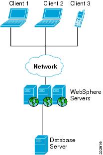
One of the WebSphere products, WebSphere Portal, manages a variety of enterprise applications and supports application development and delivery. In the Lean Retail WebSphere Solution, content development and document management functions of WebSphere Portal were tested.

Note
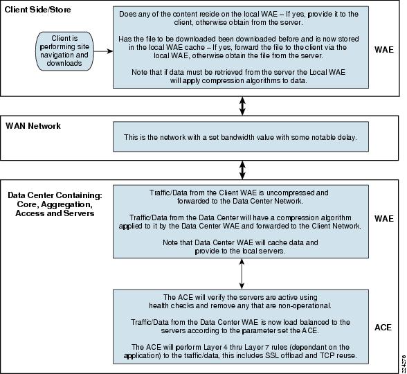
Process Flow
Figure 3 Process Flow
Solution Design
Application and Application Networking Design
Figure 4 Application and Application Networking Design
The Lean Retail Architecture uses WAAS to enhance performance and Cisco ACE to reduce and balance the load on resources in the server farm. The WAAS and Cisco ACE each provide a unique benefit to the solution, however there are additional benefits when they are used together as the two solutions are complimentary. The Cisco ACE provides load balancing to the server farm. If the application uses SSL, then the Cisco ACE can provide SSL termination offload, thereby increasing efficiency by removing the load on the servers' resources and allowing the servers to process more transactions. Increased server efficiency also results if the Cisco ACE is used to provide TCP reuse.
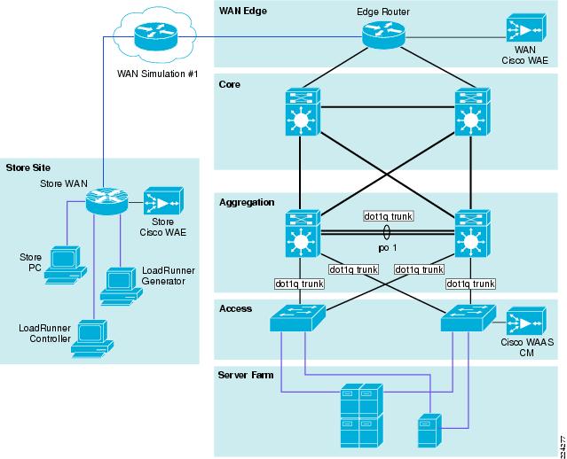
The Lean Retail Solution design is based on the Enterprise Branch Wide Area Application Services Design Guide (Enterprise Branch Design) and the Data Center Infrastructure Design Guide 2.1, both found at www.cisco.com/go/srnd.
In the Lean Retail Solution design, the WAAS Solution is installed within the Cisco Wide Area Application Engine (WAE) Appliances.
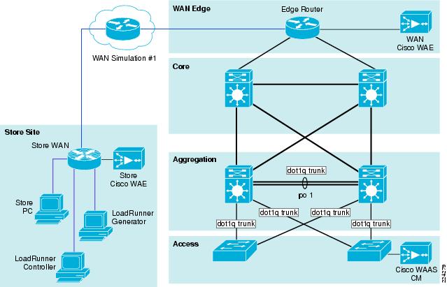
Enterprise Store
The Enterprise Branch Design guide shows the Cisco WAE appliance connected to the local store router, typically a Cisco Integrated Services Router (ISR). The design provides scalability and availability as compared to installing a Cisco WAAS Network Module within a Cisco ISR as the Cisco ISR must share its resources.
HP Mercury LoadRunner, running on a personal computer in the store, simulates users that would perform certain tasks in the application.
The traffic is redirected to the Cisco WAE via Web cache communications protocol (WCCP) from the store router. The Cisco WAE performs the following functions:
•
•
WAN Simulation
The WAN simulator provides simulations of the following WAN links:
1.
a.
2.
a.
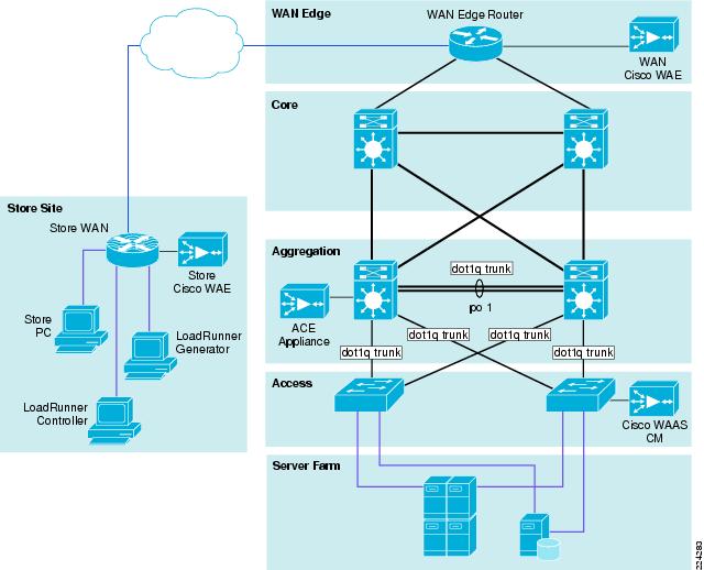
Data Center
The data center (DC) follows the design guidelines found in the Data Center Infrastructure Design Guide 2.1, a Cisco Validated Design found at http://www.cisco.com/go/srnd. The design consists of a data center WAN router, core, aggregation, and access Ethernet switching, and the server farm where the application resides. In this document, the focus is on the DC WAN router, aggregation, and the server farm. The core Ethernet switching provides routing to and from the DC WAN router and the aggregation. The access Ethernet switching provides Layer 2 connectivity for the server farms to the aggregation.
The DC WAN router performs the same function as the store WAN router by redirecting traffic to the DC Cisco WAE. The DC Cisco WAE performs the following:
•
•
Included in the data center is the Cisco WAAS central manager (CM), which runs on the Cisco WAE Appliance. The Cisco WAAS CM provides a centralized mechanism for configuring Cisco WAAS features and reporting and monitoring Cisco WAAS traffic. It can manage a topology containing thousands of Cisco WAE nodes and be accessed from any Web browser using SSL. The Cisco WAAS CM can be configured for high availability by deploying a pair of Cisco WAE appliances as central managers.
Within a Cisco WAAS topology, each Cisco WAE runs a process called central management system (CMS). The CMS process provides SSL-encrypted bidirectional configuration synchronization of the Cisco WAAS CM and the Cisco WAE appliances. The CMS process is also used to exchange reporting information and statistics at a configurable interval. When the administrator applies configuration or policy changes to a Cisco WAE appliance or a group of Cisco WAE appliances, the Cisco WAAS Central Manager automatically propagates the changes to each of the managed Cisco WAEs. Cisco WAEs that are not available to receive the changes will receive them the next time the appliances become available.
The aggregation segment contains Cisco ACE, which provides the following features:
•
•
•
•
•
Cisco ACE provides load balancing of the traffic to the server farm using one of the following methods: Round Robin, Weighted Round Robin, Least Connections, Hash address, Hash cookie, Hash Header, and Hash URL. In the Joint Solution, Least Connections was used, which selects the server with the fewest number of server connections. Cisco ACE is also used to provide SSL offload and TCP reuse.
Inter-chassis Cisco ACE redundancy was used, in which a Cisco ACE module in one Cisco Catalyst 6500 Series Switch chassis is protected by a Cisco ACE module in a peer Cisco Catalyst 6500 Series Switch chassis connected by a fault tolerant (FT) VLAN. The FT VLAN is used to transmit flow-state information, configuration synchronization information, and the redundancy heartbeat.
Server Farm
The server farm consisted of two IBM WebSphere Portal servers, a deployment manager, and an IBM DB2 database (see Figure 5). The two WebSphere portal servers are not only connected to the database server, but also to the deployment manager. A deployment manager acts as a coordinator of the multiple WebSphere portal servers. If there is only one portal server, a deployment manager is not needed. If there is more than one portal server, a deployment manager is required.
Figure 5 Server Farm
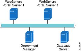
The WebSphere Portal servers run IBM WebSphere Portal Express v6.0. Each of the WebSphere Portal servers resides on the Windows 2003 enterprise server operating system. Dual Xeon processors running at 2.33 Ghz with 4 G of RAM and 4 80 G SATA hard drives were used.
The IBM WebSphere deployment manager runs IBM WebSphere Application Server Network Deployment version 6.0. The deployment manager resides on the Windows 2003 enterprise server operating system. Dual Xeon processors running at 2.33 Ghz with 4 G of RAM and 4 80 G SATA hard drives were used.
The IBM DB2 database version is 8.1.7. The IBM DB2 resides on the Windows 2003 enterprise server operating system. Dual Xeon processors running at 2.33 Ghz with 4 G of RAM and 4 80 G SATA hard drives were used. The gigabit network interface cards are "nic-teamed" for redundancy.
Packet Flow Without Cisco WAAS and Cisco ACE
Application packet flow from a remote site can be categorized into three segments, client, WAN, and server.
Figure 6 Normal Packet Flow
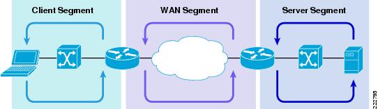
Client Segment
The client segment is defined as the location into which users are connected that allows them to obtain or retrieve data from the application residing on the server farm. Users have connected personal computers (PC) to a local external switch or an integrated switch/router. When a user opens a browser and provides a URL that points to the application residing on the server, the data is sent from the PC to the switch. The switch forwards the data to the router that connects to the wide area network (WAN).
WAN Segment
The WAN provides the connectivity from the client location to the data center where the server farm is located. The WAN is provided by a service provider (SP) with a given service level agreement (SLA). The WAN inherently introduces delay and packet loss to the data traffic (packets).
Server Segment
The server segment consists of a highly available and resilient core, aggregation, and access Ethernet switching. The core routes the data traffic to and from the WAN and the aggregation layer. The aggregation layer provides consolidation of multiple access layers and routes the access layer traffic into the core. The aggregation layer also takes the data traffic from the core layer and sends it to the appropriate access layer. The access layer provides connectivity to the server farm where the applications reside. The data traffic (URL, per the example) from the client segment transverses the data center until the data traffic is received by the appropriate server. The server's application responds to the request and responds back to the user by forwarding the appropriate data back the client segment.
Response Times
Transaction response time consists of server response time and WAN round trip time. Delays in the WAN or the time to process a request on a server lead to a longer wait times for data to be viewed by the end user.
Packet Flow with Cisco WAAS and Cisco ACE
Figure 7 Packet Flow with Cisco WAAS and Cisco ACE
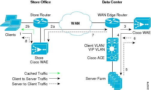
The following sequence describes the handshake between a client and the server farm and the data transfer phase:
1.
2.
3.
4.
5.
6.
7.
8.
Implementing and Configuring the Cisco ACE Solution
Implementation
Implementation Overview
The Cisco ACE module used in this solution is deployed in a Cisco Catalyst 6509 switch in the data center aggregation layer. The Cisco ACE module is deployed in routed mode where the client and server side VLANs each support unique IP subnets. In this deployment mode the Cisco ACE acts as the default gateway for the application servers.
What Was Implemented
Key features implemented on the Cisco ACE module to support this application are:
•
•
•
•
•
What Was Not Implemented/Tested
The following was not implemented in this solution:
•
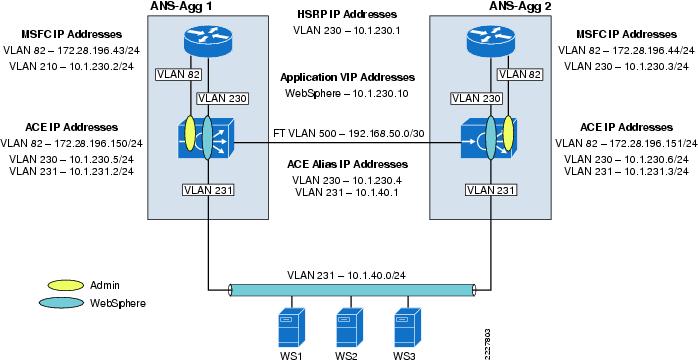
Network Topology
Figure 8 Network Topology
Hardware or Components
Table 1 Hardware
ACE20-MOD-K9
Must be inserted into a Cisco Catalyst 65XX chassis
N/A
Console port
957928 kB
Note
Software
Features and Functionality
Features, Services, and Application Design Considerations
WebSphere servers support active cookie persistence, passive cookie persistence, and SSL persistence. In terms of the Cisco ACE, active cookie persistence is the Cisco ACE cookie insert feature which is used for the Lean Retail WebSphere solution. The Cisco ACE inserts the cookie on behalf of the server upon the return request, so the Cisco ACE can perform cookie stickiness even when the servers are not configured to set cookies. The cookie contains information that the Cisco ACE uses to ensure persistence to a specific real server. Refer to Configuration Task Lists and Appendix A—Cisco ACE Configuration for configuration information. Note that for the SSL offload solution, cookie persistance was done using the learned cookie from the server as shown in Appendix A—Cisco ACE Configuration.
High Availability, Scalability, and Redundancy
The Cisco ACE also offers multitiered redundancy, availability, and scalability for maximum protection. It is the only product in the industry that offers three types of high availability:
•
•
•
All these application availability modes provide rapid, stateful application redundancy with replication of connection state and sticky tables.
Inter-chassis and Inter-partition redundancy is used in the Lean Retail WebSphere solution. Refer to Configuration Task Lists and Appendix A—Cisco ACE Configuration for configuration information.
Configuration Task Lists
This section describes the steps necessary to configure the equipment.
Installing Cisco ACE and MSFC Configuration
A Cisco ACE module interacts with clients and servers via VLANs that are set up in Cisco Catalyst 6500 Series/Cisco 7600 Series Supervisor Engine 720 (Sup 720). These VLANs must be configured on Sup720 to be allowed to be sent to the Cisco ACE module. Without this configuration, by default Cisco ACE does not receive any traffic from any VLAN.
The following sample configuration steps are performed on the MSFC. Refer to Appendix A—Cisco ACE Configuration for a complete configuration.
Step 1
vlan 230name ACE-CLIENT!vlan 231name ACE-SERVER!vlan 500name ACE-FT-VLAN!Step 2
For this deployment, Cisco ACE is installed in slot 3 in the Cisco Catalyst 6500 chassis. The following configuration needs to be added to allow Cisco ACE-specific VLAN traffic to be directed towards Cisco ACE:
svclc multiple-vlan-interfacessvclc module 3 vlan-group 1svclc vlan-group 1 230,231,500Step 3
The SVI (interface VLAN) configuration defines Layer 3 instance on the router MSFC. The Cisco ACE client side VLAN SVI configuration is:
interface Vlan230description ACE Client Side VLANip address 10.1.230.2 255.255.255.0standby 230 ip 10.1.230.1standby 230 Priority 120
Virtualization
Virtualization is a method to allocate available resources into two or more contexts for security and management purposes. Up to 250 (5 with no additional license requirements) contexts can be configured on Cisco ACE. Resources can be allocated to each context to avoid a single context consuming the entire pool of resources. This document only covers key virtualization configuration. Within each context, Domains and Role Base Access Controls (RBACs) can be further configured to provide additional security and access control to the resources.
Context Configuration
Sample context configuration steps are:
Step 1
ACE_1/Admin(config)# resource-class Gold<cr> Carriage return.The different resources that can be segmented are:
ACE_1/Admin(config-resource)# limit-resource ?acl-memory Limit ACL memoryall Limit all resource parametersbuffer Set resource-limit for buffersconc-connections Limit concurrent connections (thru-the-box traffic)mgmt-connections Limit management connections (to-the-box traffic)proxy-connections Limit proxy connectionsrate Set resource-limit as a rate (number per second)regexp Limit amount of regular expression memorysticky Limit number of sticky entriesxlates Limit number of Xlate entriesStep 2
A context is configured by giving it a name, allocating VLANs, and assigning it to a resource-class (previous step):
context webspheredescription WebSphere Testingallocate-interface vlan 230-231member GoldStep 3
ACE_1/Admin# changeto websphere
Redundancy/High Availability
To provide high availability and redundancy, Cisco ACE can be set up and configured in a redundant mode. Cisco ACE can be configured in a typical active/backup redundancy mode or active/active (per context) redundancy mode.
ACE_1/Admin(config)# ft interface vlan 500 Create a VLAN interface for the FT trafficACE_1/Admin(config-ft-intf)# ip address 192.168.50.1 255.255.255.252ACE_1/Admin(config-ft-intf)# peer ip address 192.168.50.2 255.255.255.252ACE_1/Admin(config-ft-intf)# no shutdownACE_1/Admin(config)# ft peer 1 Configure FT peer for this ACE moduleACE_1/Admin(config-ft-peer)# ft-interface vlan 500 Assign FT VLAN to this peerACE_1/Admin(config-ft-peer)# heartbeat count 10ACE_1/Admin(config-ft-peer)# heartbeat interval 300ACE_1/Admin(config)# ft group 1 Create a fault tolerance groupACE_1/Admin(config-ft-group)# peer 1ACE_1/Admin(config-ft-group)# priority 200ACE_1/Admin(config-ft-group)# preemptACE_1/Admin(config-ft-group)# associate-context Admin Admin context, ACTIVE in this ACEACE_1/Admin(config-ft-group)# inservice Enable this FT groupACE_1/Admin(config)# ft group 3 Create a fault tolerance groupACE_1/Admin(config-ft-group)# peer 1ACE_1/Admin(config-ft-group)# priority 200ACE_1/Admin(config-ft-group)# associate-context websphere WebSphere context, ACTIVE in this ACEACE_1/Admin(config-ft-group)# inservice Enable this FT groupBy assigning context(s) to a FT group, a network administrator can create multiple groups for multiple contexts where the ACTIVE contexts can be distributed among the two Cisco ACE modules. This setup provides active/active redundancy setup for load sharing and high availability.
Remote Management Access
To access the Cisco ACE module remotely using Telnet, SSH, SNMP, HTTP, or HTTPS or to allow ICMP access to the Cisco ACE module, a policy must be defined and applied to the interface(s) the access is entering.
The configuration steps in this section are required for both the Admin context and the application context. The following example is for the application context. Refer to Appendix A—Cisco ACE Configuration for a complete configuration.
Step 1
class-map type management match-any REMOTE-MGMT10 match protocol ssh any20 match protocol telnet any30 match protocol icmp any40 match protocol http any50 match protocol https anyStep 2
policy-map type management first-match REMOTE-ACCESSclass REMOTE-MGMTpermitStep 3
interface vlan 230service-policy input REMOTE-ACCESSinterface vlan 231service-policy input REMOTE-ACCESS
Configuring Interface(s) and Default Gateway
Interface VLANs need to be configured for Layer 3 connectivity to Cisco ACE. Service policies for load balancing, security, and management access to Cisco ACE are also applied at the interface VLAN level.
The configuration steps in this section are required for both the Admin context and the application context. The following example is for the application context. Refer to Appendix A—Cisco ACE Configuration for a complete configuration.
Step 1
access-list ANYONE line 10 extended permit icmp any anyaccess-list ANYONE line 20 extended permit ip any anyStep 2
interface vlan 230ip address 10.1.230.5 255.255.255.0peer ip address 10.1.230.6 255.255.255.0alias 10.1.230.4 255.255.255.0interface vlan 231ip address 10.1.50.2 255.255.255.0peer ip address 10.1.50.3 255.255.255.0alias 10.1.50.1 255.255.255.0Step 3
interface vlan 230access-group input ANYONEaccess-group output ANYONEservice-policy input REMOTE-ACCESSno shutdowninterface vlan 231access-group input ANYONEaccess-group output ANYONEservice-policy input REMOTE-ACCESSno shutdownStep 4
ip route 0.0.0.0 0.0.0.0 10.1.230.1Step 5
Type show interface and verify the VLANs are up and assigned from the supervisor.
Here is an example of a working output:
vlan230 is upHardware type is VLANMAC address is 00:1b:d5:9b:88:edVirtual MAC address is 00:0b:fc:fe:1b:02Mode : routedIP address is 10.1.230.5 netmask is 255.255.255.0FT status is activeDescription:Client side vlanMTU: 1500 bytesLast cleared: neverAlias IP address is 10.1.230.4 netmask is 255.255.255.0Peer IP address is 10.1.230.6 Peer IP netmask is 255.255.255.0Assigned from the Supervisor, up on Supervisor53808467 unicast packets input, 17900167965 bytes7331701 multicast, 7776 broadcast0 input errors, 0 unknown, 0 ignored, 0 unicast RPF drops91028995 unicast packets output, 5455629020 bytes4 multicast, 5202 broadcast0 output errors, 0 ignoredvlan231 is upHardware type is VLANMAC address is 00:1b:d5:9b:88:edVirtual MAC address is 00:0b:fc:fe:1b:02Mode : routedIP address is 10.1.231.2 netmask is 255.255.255.0FT status is activeDescription:Server side vlanMTU: 1500 bytesLast cleared: neverAlias IP address is 10.1.231.1 netmask is 255.255.255.0Peer IP address is 10.1.231.3 Peer IP netmask is 255.255.255.0Assigned from the Supervisor, up on Supervisor83222640 unicast packets input, 95861661879 bytes1118208 multicast, 47974 broadcast0 input errors, 0 unknown, 0 ignored, 0 unicast RPF drops53089290 unicast packets output, 4304456323 bytes4 multicast, 14950 broadcast0 output errors, 0 ignored
Probes
Cisco ACE uses probe, one of the available keep-alive methods, to verify the availability of a real server. Probe is configured by defining its type and name.
There are different types of probes that can be configured on Cisco ACE:
ACE_1/Admin(config)# probe ?dns Configure dns probeecho Configure echo probefinger Configure finger probeftp Configure ftp probehttp Configure http probehttps Configure https probeicmp Configure icmp probeimap Configure imap probeldap Configure ldap probepop Configure pop proberadius Configure radius probescripted Configure script probesmtp Configure smtp probetcp Configure tcp probetelnet Configure telnet probeudp Configure udp probeSome key timers and parameters need to be tuned when probes are configured. The value for these parameters influences how rapidly Cisco ACE (or any load balancer) takes a server out of rotation and brings it back in service.
The following parameters need to be tuned for probes of any type (icmp, udp, tcp, http, https, scripted):
•
•
•
–
–
These additional parameters should be configured for TCP, HTTP, and HTTPS probes:
•
•
•
•
–
–
–
–
•
This parameter is only applicable to HTTP/HTTPS probes.
•
–
–
This parameter is only applicable to HTTP/HTTPS probes.
•
ssl cipher:RSA_EXPORT1024_WITH_DES_CBC_SHA EXP1024-DES-CBC-SHA CipherRSA_EXPORT1024_WITH_RC4_56_MD5 EXP1024-RC4-MD5 CipherRSA_EXPORT1024_WITH_RC4_56_SHA EXP1024-RC4-SHA CipherRSA_EXPORT_WITH_DES40_CBC_SHA EXP-DES-CBC-SHA CipherRSA_EXPORT_WITH_RC4_40_MD5 EXP-RC4-MD5 CipherRSA_WITH_3DES_EDE_CBC_SHA 3DES-EDE-CBC-SHA CipherRSA_WITH_AES_128_CBC_SHA AES-128-CBC-SHA CipherRSA_WITH_AES_256_CBC_SHA AES-256-CBC-SHA CipherRSA_WITH_DES_CBC_SHA DES-CBC-SHA CipherRSA_WITH_RC4_128_MD5 RC4-MD5 CipherRSA_WITH_RC4_128_SHA RC4-SHA Cipherssl versions:SSLv2 SSL Version 2.0SSLv3 SSL Version 3.0TLSv1 TLS Version 1.0This parameter is only applicable to HTTPS probes.
The following are configurations for TCP and ICMP:
•
probe tcp PROBE-TCPinterval 2faildetect 2passdetect interval 10passdetect count 2•
probe icmp PINGinterval 2faildetect 2Real Server
Load balancer selects the real servers (called rserver in Cisco ACE) to send the intended traffic based on certain sets of criteria. When configuring a real server, be aware that real server name is case sensitive. The minimum configuration needed for rserver configuration is the IP address and configuring the rserver as inservice.
The same rserver can be used in multiple server farms (shown later in the document). If an rserver is made no inservice at the rserver level, then it is taken out of rotation from every server farm on which it is configured. This provides the flexibility to take a server completely out of rotation with a single command.
To take a server out of rotation on a per-server farm basis, rserver should be made no inservice at the server farm level.
The following is an example of configuring rserver on Cisco ACE:
rserver host WL1ip address 10.1.50.51inserviceServer Farm
A server farm is a logical collection of real servers (rservers) that load balancer selects based on certain sets of criteria. As with real server, serverfarm name is also case sensitive.
Basic server farm configuration includes adding rservers and probes to the server farm.
Key configuration options within server farm sub-configuration mode are:
•
A configurable option is failaction purge, which forces Cisco ACE to remove the connections established to that real and send TCP RST(s) towards the client(s) and real(s).
•
–
–
<1-65535> Specify slowstart duration in seconds
–
•
•
retcode <min> <max> check <remove|count|log> <threshold value> resume-service <value
in seconds>
•
•
The following is an example of basic server farm configuration:
serverfarm host WEBSPHEREpredictor leastconnsprobe ICMPrserver WL1inservicerserver WL2inserviceLayer 4 Load Balancing
Cisco ACE uses class-map, policy-map, and service-policy to classify, enforce, and take action on incoming traffic. Traffic trying to reach a virtual IP address on a certain port can be used as classifiers for Layer 4 load balancing as the classification is only based on destination IP and destination port.
Note
The following example shows the configuration steps needed:
Step 1
class-map match-all VIP-HTTP-102 match virtual-address 10.1.230.10 tcp eq 7041Step 2
policy-map type loadbalance first-match VIP-POLICY-10class class-defaultsticky-serverfarm SRC-IP-STICKYStep 3
policy-map multi-match LB-VIPclass VIP-HTTP-10loadbalance vip inserviceloadbalance policy VIP-POLICY-10loadbalance vip icmp-replyStep 4
interface vlan 230service-policy input LB-VIP
Layer 7 Load Balancing
Similar to Layer 4 policy, Cisco ACE uses class-map, policy-map, and service-policy to classify and enforce a Layer 7 policy. Cisco ACE uses additional information such as URL, HTTP header, or cookie to make a load balancing decision. The following example shows the configuration steps for URL-based matching. Similar steps can be used for cookie or header matching.
The following example shows the configuration steps needed:
Step 1
class-map type http loadbalance match-any L7-URL2 match http url .*.htmStep 2
parameter-map type http L7-mapcase-insensitiveStep 3
class-map match-all VIP-HTTP-102 match virtual-address 10.1.230.10 tcp eq 7041Step 4
policy-map type loadbalance first-match L7-matchclass L7-URLsticky-serverfarm STICKY-INSERT-COOKIEclass class-defaultserverfarm WEBSPHEREStep 5
policy-map multi-match LB-VIPclass VIP-HTTP-10loadbalance vip inserviceloadbalance policy L7-matchloadbalance vip icmp-replyStep 6
interface vlan 230service-policy input LB-VIP
Stickiness (Session Persistence)
Session persistence or sticky configuration allows multiple connections from the same client to be sent to the same real server by Cisco ACE. Cisco ACE supports stickiness based on source/destination (or both) IP address and HTTP cookies. Cisco ACE insert cookie persistence is when the Cisco ACE inserts the cookie on behalf of the server upon the return request, so that the Cisco ACE can perform cookie stickiness even when the servers are not configured to set cookies. The cookie contains information that the Cisco ACE uses to ensure persistence to a specific real server.
The following are the sample configurations for various sticky types along with working demonstrations.
Cisco ACE Inserted Cookie Stickiness
The following steps are needed to configure stickiness based on Cisco ACE inserted cookie:
Step 1
sticky http-cookie acecookie STICKY-INSERT-COOKIEcookie insertserverfarmStep 2
policy-map type loadbalance first-match L7-MATCHclass L7-URLsticky-serverfarm STICKY-INSERT-COOKIEclass class-defaultserverfarm WEBSPHEREStep 3
policy-map multi-match LB-VIPclass VIP-HTTP-10loadbalance vip inserviceloadbalance policy L7-MATCHloadbalance vip icmp-replyStep 4
interface vlan 230description Client side vlanip address 10.1.230.5 255.255.255.0alias 10.1.230.4 255.255.255.0peer ip address 10.1.230.6 255.255.255.0access-group input ANYONEservice-policy input LB-VIPservice-policy input REMOTE-MANAGEMENTno shutdown
SSL Termination
SSL termination configuration on Cisco ACE provides SSL traffic termination on Cisco ACE instead of on the servers. This allows the offloading of server resources and also provides HTTP request inspection for various load balancing functionalities.
Front End SSL Termination
With SSL termination on the Cisco ACE, client to Cisco ACE traffic is SSL encrypted, but Cisco ACE to server traffic is clear-text. The configuration steps to implement front end SSL termination are:
Step 1
ACE_1/testfeature# crypto generate key 512 testkey.keyACE_1/testfeature# show crypto key allFilename Bit Size Type-------- -------- ----testkey.key 512 RSAStep 2
crypto csr-params testparamscountry USstate Californialocality SJorganization-name ASorganization-unit TAScommon-name www.testssl.comserial-number cisco123Step 3
ACE_1/testfeature# crypto generate csr testparams testkey.key-----BEGIN CERTIFICATE REQUEST-----MIIBHjCByQIBADBkMQswCQYDVQQGEwJVUzETMBEGA1UECBMKQ2FsaWZvcm5pYTELMAkGA1UEBxMCU0oxCzAJBgNVBAoTAkFTMQwwCgYDVQQLEwNUQVMxGDAWBgNVBAMTD3d3dy50ZXN0c3NsLmNvbTBcMA0GCSqGSIb3DQEBAQUAA0sAMEgCQQC+xphqQJn9EOzOhkFfVCVO5SYJj7nVjWmaslVZOi7TYKzFgXtJexMt0Y1VyO7XY+U5XdZuvoxEcO4rdAGzo84HAgMBAAGgADANBgkqhkiG9w0BAQQFAANBAAL9EzKcYyOrL3XYc7YGSTgpa1B8tTpCpJIVwrHwolyK3OzvfudLTbF7CQ2V3jUYS//sf2Cei8fe+voKIQE9nI4=-----END CERTIFICATE REQUEST-----Step 4
An SSL certificate can be obtained from various Certificate Authority (CA) companies like VERISIGN. The following example shows using a CISCO router as a CA:
OS-CA-SERVER#crypto pki server CDN-CA request pkcs10 terminal pem% Enter Base64 encoded or PEM formatted PKCS10 enrollment request.% End with a blank line or "quit" on a line by itself.-----BEGIN CERTIFICATE REQUEST-----MIIBHjCByQIBADBkMQswCQYDVQQGEwJVUzETMBEGA1UECBMKQ2FsaWZvcm5pYTELMAkGA1UEBxMCU0oxCzAJBgNVBAoTAkFTMQwwCgYDVQQLEwNUQVMxGDAWBgNVBAMTD3d3dy50ZXN0c3NsLmNvbTBcMA0GCSqGSIb3DQEBAQUAA0sAMEgCQQC+xphqQJn9EOzOhkFfVCVO5SYJj7nVjWmaslVZOi7TYKzFgXtJexMt0Y1VyO7XY+U5XdZuvoxEcO4rdAGzo84HAgMBAAGgADANBgkqhkiG9w0BAQQFAANBAAL9EzKcYyOrL3XYc7YGSTgpa1B8tTpCpJIVwrHwolyK3OzvfudLTbF7CQ2V3jUYS//sf2Cei8fe+voKIQE9nI4=-----END CERTIFICATE REQUEST-----Quit% Granted certificate:-----BEGIN CERTIFICATE-----MIIB6TCCAVKgAwIBAgIBCTANBgkqhkiG9w0BAQQFADARMQ8wDQYDVQQDEwZDRE4tQ0EwHhcNMDYwNDI2MTgxNjQzWhcNMDcwNDI2MTgxNjQzWjBkMQswCQYDVQQGEwJVUzETMBEGA1UECBMKQ2FsaWZvcm5pYTELMAkGA1UEBxMCU0oxCzAJBgNVBAoTAkFTMQwwCgYDVQQLEwNUQVMxGDAWBgNVBAMTD3d3dy50ZXN0c3NsLmNvbTBcMA0GCSqGSIb3DQEBAQUAA0sAMEgCQQC+xphqQJn9EOzOhkFfVCVO5SYJj7nVjWmaslVZOi7TYKzFgXtJexMt0Y1VyO7XY+U5XdZuvoxEcO4rdAGzo84HAgMBAAGjQjBAMB8GA1UdIwQYMBaAFNKc5JGHmabT17tofs9CUD8mxVURMB0GA1UdDgQWBBQAL2ptyfN85SoVNdEiGRav8nI8lTANBgkqhkiG9w0BAQQFAAOBgQAUHyfbs+aMapSEFXmdlKPh8F67gGuYBdyWxmXjR7KVErDxde+4UqJCkNP4R2m11g30j6UveG2wLiP7C4IZHzGfFXUbzdPhaZ1838qgZlFn+lXPtCrayto1PitWeuPbCwLTxmE2vWWLw6lwEzguVbF+6t0nmLAkyiYsuz/MOiql/g==-----END CERTIFICATE-----IOS-CA-SERVER#Step 5
ACE_1/testfeature# crypto import terminal testcert.pemPlease enter PEM formatted data. End with "quit" on a new line.-----BEGIN CERTIFICATE-----MIIB6TCCAVKgAwIBAgIBCTANBgkqhkiG9w0BAQQFADARMQ8wDQYDVQQDEwZDRE4tQ0EwHhcNMDYwNDI2MTgxNjQzWhcNMDcwNDI2MTgxNjQzWjBkMQswCQYDVQQGEwJVUzETMBEGA1UECBMKQ2FsaWZvcm5pYTELMAkGA1UEBxMCU0oxCzAJBgNVBAoTAkFTMQwwCgYDVQQLEwNUQVMxGDAWBgNVBAMTD3d3dy50ZXN0c3NsLmNvbTBcMA0GCSqGSIb3DQEBAQUAA0sAMEgCQQC+xphqQJn9EOzOhkFfVCVO5SYJj7nVjWmaslVZOi7TYKzFgXtJexMt0Y1VyO7XY+U5XdZuvoxEcO4rdAGzo84HAgMBAAGjQjBAMB8GA1UdIwQYMBaAFNKc5JGHmabT17tofs9CUD8mxVURMB0GA1UdDgQWBBQAL2ptyfN85SoVNdEiGRav8nI8lTANBgkqhkiG9w0BAQQFAAOBgQAUHyfbs+aMapSEFXmdlKPh8F67gGuYBdyWxmXjR7KVErDxde+4UqJCkNP4R2m11g30j6UveG2wLiP7C4IZHzGfFXUbzdPhaZ1838qgZlFn+lXPtCrayto1PitWeuPbCwLTxmE2vWWLw6lwEzguVbF+6t0nmLAkyiYsuz/MOiql/g==-----END CERTIFICATE-----quitStep 6
ACE_1/testfeature# crypto verify testkey.key testcert.pemKeypair in testkey.key matches certificate in testcert.pem.Step 7
a.
parameter-map type ssl sslparamscipher RSA_WITH_RC4_128_MD5version SSL3b.
ssl-proxy service testsslkey testkey.keycert testcert.pemssl advanced-options sslparamsStep 8
serverfarm host farm-3probe test-tcprserver real40 80inservicerserver real41 80inserviceclass-map match-all VIP-SSL-1752 match virtual-address 10.74.1.175 tcp eq httpspolicy-map type loadbalance first-match vip-ssl-175class class-defaultserverfarm farm-3policy-map multi-match LB-VIPclass VIP-WEB-175loadbalance vip inserviceloadbalance policy L7-matchloadbalance vip icmp-replyappl-parameter http advanced-options L7-mapclass VIP-SSL-175loadbalance vip inserviceloadbalance policy vip-ssl-175loadbalance vip icmp-replyssl-proxy server testsslStep 9
interface vlan 749ip address 10.74.1.5 255.255.255.0access-group input everyoneaccess-group output everyoneservice-policy input REMOTE-ACCESSservice-policy input LB-VIPno shutdown
Configuration and Menus
See Appendix A—Cisco ACE Configuration for the configuration used to support WebSphere Portal.
Troubleshooting Configuration
These show commands can help troubleshoot issues with the configuration:
•
•
•
•
•
•
•
•
•
•
•
•
Configuration Rollback
Configuration rollback allows the administrator to revert back to a previous good configuration when the new configuration does not work.
Step 1
ACE_1/testfeature# checkpoint create nameStep 2
ACE_1/testfeature# show checkpoint allACE_1/testfeature# checkpoint rollback config-05-09-06
Results and Conclusions
Figure 9 SSL Direct to Server

Number of successful transaction: 6904
Figure 10 SSL Offload
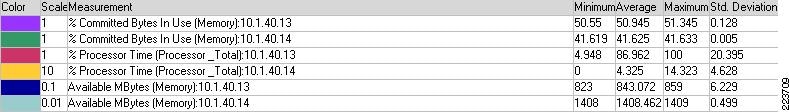
Note
Number of successful transaction: 8422
Note that the processor was slightly higher compared to the SSL direct, but this was due to the number of more successful transactions that occurred during SSL offload testing.
Implementing and Configuring the Cisco WAAS Solution
Implementation
Implementation Overview
The Cisco WAAS solution requires a minimum of three Cisco Wide Area Application Engine (WAE) appliances to auto-discover and deliver applicable application optimizations. One Cisco WAE is placed in the enterprise data center and the other at the store site. The enterprise data center Cisco WAE is placed on the WAN edge connected to the WAN router. The third Cisco WAE is used for the Central Manager. The design offloads the Cisco WAE device from the local store router and leverages the available ports on a local switch. This design provides scalability and availability for the solution.
What Was Implemented
Cisco WAAS technology requires the efficient and predictable interception of application traffic to produce results. It is critical that the Cisco WAE device see the entire TCP conversation. At the WAN edge, Cisco routers support the following four methods of traffic interception:
•
•
•
•
WCCPv2 is the most common method used in the remote store environment; therefore, WCCPv2 has been leveraged for this solution.
Note
What Was Not Implemented
The following was not implemented in this solution:
•
Network Topology
Figure 11 Network Topology
Hardware or Components
Software
Features and Functionality
Features, Services, and Application Design Considerations
Most multi-tiered applications support Web-based clients in addition to native application clients. Web-based clients use port 80 to communicate to the Web server. Applications in this test use port 80. In the context of Cisco WAAS, port 80 is accelerated by default; no further configuration in the Cisco WAE is necessary unless the application requires ports that are not part of the default application profile. For applications that use TCP ports that are not defined in the default application profile, you must define ports to the existing application profile or create a new application profile with the associated ports. With the recommended design of Cisco WAAS at the WAN edge, client data only traverse the Cisco WAEs once, at the ingress/egress of the data center. Further application communication between the Web servers, application servers, and database servers are within the data center and are not affected by Cisco WAAS.
Transport Flow Optimization (TFO), Data Redundancy Elimination (DRE), and Lempel-Ziv (LZ)-compression, the three key technologies of Cisco WAAS, are enabled by default. Each of these features and functionalities are described in Features and Functionality. The net results are reduced traffic and decreased latency across the WAN. Since Cisco WAAS deployments are transparent to the network and application, applications do not need to be aware of the added functionalities and continue to work as-is, but with decreased response time and increased traffic throughput and transactions.
Additional information on Cisco WAAS data center and branch designs are available at:
•
•
Scalability and Capacity Planning
Cisco WAE farms can scale up to 32 devices with WCCP and up to 16000 with Cisco ACE load balancing. Cisco WAAS services scale linearly in a N+1 configuration. In addition to the Max Optimized TCP connections, the fan out ratio between the DC Cisco WAE and store Cisco WAE have to be considered. The fan out ratio is determined by a number of factors, such as the number of Cisco WAEs in the store offices, amount of network traffic, and number of TCP connections. A sizing tool is available internally that can help automate sizing decisions. NetFlow, NetQoS, and other network analysis tools can provide additional traffic flow information for increased accuracy in scalability and capacity planning.
Store devices range from the NME-WAE-302 for very small offices to the 612-4GB or even higher models for bigger store sites. WAE 7326 and up are designed for data center installations.
High Availability
Cisco WAAS deployments are transparent to the application. The application client and server do not know Cisco WAAS is optimizing traffic flows. High availability is built into the WCCP interception. When WCCP is not active or if Cisco WAAS devices are not functioning, WCCP does not forward traffic to the Cisco WAEs, resulting in un-optimized traffic flow. This is the worse case scenario; traffic flow continues but is not optimized.
Device High Availability
The Cisco WAEs have many built-in high availability features. The disk subsystem is recommended to be configured with RAID 1 protection. RAID 1 is mandatory when two or more drives are installed in the Cisco WAE. With RAID 1, failure of the physical drive does not affect normal operations. Failed disks can be replaced during planned downtime. Multiple network interfaces are available. Standby interfaces can be configured for interface failover. A standby interface group guards against network interface failure on the Cisco WAE and switch. When connected to separate switches in active/standby mode, the standby interface protects the Cisco WAE from switch failure.
N+1 Availability
Cisco WAEs and the network provide additional high availability (HA) capabilities. Routers can be configured redundantly providing HSRP or GLBP services. Cisco WAEs can configured in a N+1 configuration. N+1 configuration provides scalability and availability. This design calls for N number of Cisco WAEs for a specific workload, then add a standby Cisco WAE. Since the workload always distributes evenly among the Cisco WAEs, the standby Cisco WAE is utilized, reducing overall workload. In the event that a Cisco WAE fails, the rest of Cisco WAEs can resume normal workload.
Configuration Task Lists
The following subsections describe the information required prior to configuration of the equipment.
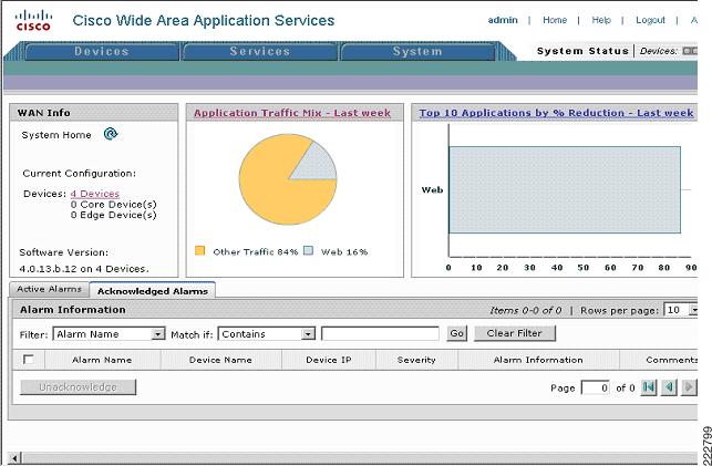
Central Manager
Central Manager (CM) is the management component of Cisco WAAS. CM provides a GUI for configuration, monitoring, and management of multiple store and data center Cisco WAEs. CM can scale to support thousands of Cisco WAE devices for large-scale deployments. The CM is necessary for making any configuration changes via the Web interface. In the event of CM failure, Cisco WAEs continue to function, however changes cannot be made using the Web pages on the CM until the CM comes back online.
Cisco WAEs need to connect to the CM on the initial setup. The registration process adds the Cisco WAE to the CM and initializes the local Cisco WAE data base. When disk encryption on the Cisco WAE is enabled, the CM must be available to distribute the encryption key in the event the Cisco WAE reboots.
Centralized reporting can be obtained from the CM. Individually, the Cisco WAEs provide basic statistics via the CLI and local device GUI. System-wide application statistics are available from the CM GUI. Detailed reports such as total traffic reduction, application mix, and pass-through traffic can be obtained from CM GUI.
The following example shows the configuration steps needed to configure CM.
Note
Step 1
device mode central-managerStep 2
interface GigabitEthernet 1/0ip address 10.1.21.2 255.255.255.0Step 3
ip default-gateway 10.1.21.1Step 4
primary-interface GigabitEthernet 1/0Step 5
ntp server 10.1.6.20Step 6
cms enableStep 7
Figure 12 Cisco WAAS Central Manager
Store and Data Center Router
The store and data center router provides WCCP interception points for Cisco WAAS. Without WCCP interception, Cisco WAAS does not know where to obtain and optimize traffic flow. Different methods of interception and redirection are supported by routers and switches. Redirection methods depend on the speed requirement and router/switch platform. In this deployment, Generic Router Encapsulation (GRE) redirection is used.
The loopback interface on the router is essential for identifying the router ID. While any IP address can be used to identify the router ID, the loopback interface is preferred over the physical interfaces. Loopback interfaces are always available; there are no physical ties to them. Other routing protocols also use loopback interfaces as a preferred method for naming the router ID. With the IP address tied to a specific physical interface, when the physical interface goes down, the IP address becoming unavailable, causing unexpected issues with WCCP groups.
Step 1
interface Loopback0ip address 10.1.6.21 255.255.255.255WCCP service 61 and 62 direct the router to re-route traffic from the interface to the WCCP group. Service 61 redirects ingress traffic and service 62 redirects egress traffic. Both service 61 and 62 are needed to complete redirect bi-directional traffic flow. WCCP is an open standard. Other equipment that implements the WCCP protocol can participate in the WCCP group. Passwords should be assigned to WCCP groups to prevent rogue traffic interception and redirection.
Step 2
ip wccp 61 password ANSip wccp 62 password ANSStep 3
interface Vlan301description WAE vlan - 301ip address 10.1.12.1 255.255.255.0Step 4
ip wccp redirect exclude inStep 5
ip flow egressStep 6
interface FastEthernet1/0description WAE portswitchport access vlan 301Step 7
interface Vlan300description client vlan - 300ip address 10.1.11.1 255.255.255.0Step 8
ip wccp 61 redirect inip wccp 62 redirect outStep 9
ip flow egressStep 10
ntp server 10.1.6.20Step 11
ip flow-export source Loopback0ip flow-export version 5ip flow-export destination 10.1.70.10 9995
WAE-612-K9, WAE-7326-K9
Step 1
device mode application-acceleratorStep 2
interface GigabitEthernet 1/0ip address 10.1.20.2 255.255.255.0Step 3
ip default-gateway 10.1.20.2Step 4
primary-interface GigabitEthernet 1/0Step 5
wccp version 2Step 6
wccp router-list 1 10.1.20.1Step 7
wccp tcp-promiscuous router-list-num 1 password ciscoStep 8
ntp server 10.1.20.1Step 9
central-manager address 10.1.21.2Step 10
cms enableStep 11
flow monitor tcpstat-v1 host 10.1.70.11flow monitor tcpstat-v1 enable
Configuration and Menus
See Appendix B—Cisco WAE Configurations for the configuration used by WebSphere Portal.
Troubleshooting Configuration
Cisco WAE Commands
These show commands can help troubleshoot issues with the configuration:
•
•
•
•
•
Router Commands
•
•
•
•
Summary and Conclusions
The Cisco Lean Retail WebSphere design provides best practices and implementation guidance that optimizes WebSphere application availability, performance, and security while lowering application ownership costs.
All of the WAAS test results indicate significant round trip time and bandwidth savings performance improvements.
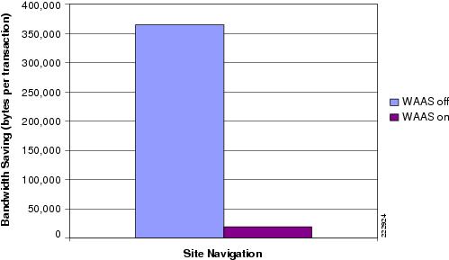
Figure 13 Bandwidth Savings for 1.544 Mbps WAN Link
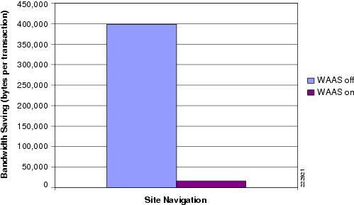
Figure 13 shows the amount data volume traversing the 1.544 Mbps WAN link with and without the Cisco WAAS device that was observed during in a 30 minute cycle with 40 users performing site navigation on the WebSphere Portal application. Figure 13 is based on the total amount data passing through the WAN divided by the total number of transactions under the conditions identified earlier.
The Cisco WAAS device reduces the amount of unnecessary data that traverses the WAN by locally caching data and using compression algorithms on the data the must traverse the WAN. As seen in Figure 13, the Cisco WAAS-enabled network becomes more efficient as less data must traverse the WAN.
With this efficiency, the end-user response time is faster and more transactions can occur, as shown in Figure 14 and Figure 15. Figure 14 shows the decreased average response time with Cisco WAAS enabled. This would result in the end-user obtaining quicker responses from the application and allowing more transactions to occur as the end-user is not waiting as long for the responses, as seen in the transaction summary charts.
Figure 14 Response Time for 1.544 Mbps WAN Link
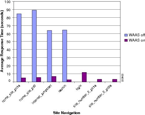
Figure 15 indicates the number of transactions that were observed for the same 30 minute cycle.
Figure 15 Number of Transactions for 1.544 Mbps WAN Link—With and Without Cisco WAAS
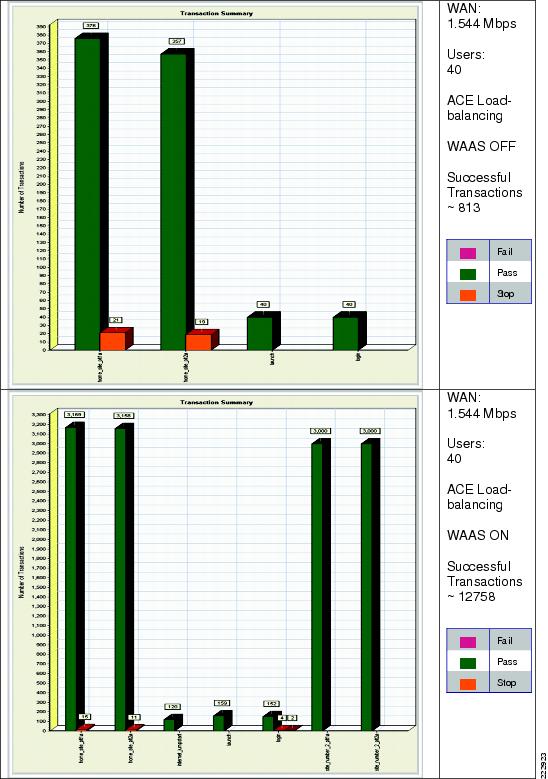
Figure 16 provides the amount data volume traversing the 512 Kbps WAN link with and without the Cisco WAAS device that was observed during in a 30 minute cycle with 40 users performing site navigation on the WebSphere Portal application. The chart is based on the total amount data passing through the WAN divided by the total number of transactions under the conditions identified earlier.
Figure 16 Bandwidth Savings for 512 Kbps WAN Link
The Cisco WAAS device reduces the amount of unnecessary data that traverses the WAN by locally caching data and using compression algorithms on the data the must traverse the WAN. As seen in Figure 16, the Cisco WAAS-enabled network becomes more efficient as less data must traverse the WAN.
With this efficiency, the end-user response time is faster and more transactions can occur, as shown in Figure 17 and Figure 18. Figure 17 shows the decreased average response time with Cisco WAAS enabled. This would result in the end-user obtaining quicker responses from the application and allowing more transactions to occur as the end-user is not waiting as long for the responses, as seen in the transaction summary charts.
Figure 17 Response Time for 512 Kbps WAN Link
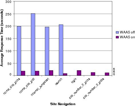
Figure 18 indicates the number of transactions that were observed for the same 30 minute cycle.
Because of the size of this WAN link, it became very congested with 40 users performing site navigation. Comparing to 1.544 Mbps WAN link, average response time is longer and the number of transactions are smaller, with and without Cisco WAAS.
Figure 18 Number of Transactions for 512 Kbps WAN Link—With and Without Cisco WAAS
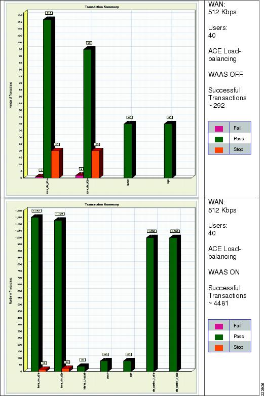
In summary, with Cisco WAAS enabled the WAN link becomes more efficient, allowing transactions to respond to end-user requests. The Cisco WAAS devices remove the congestion by reducing the amount of unnecessary data traffic that traverses the WAN by locally caching data and using compression algorithms on the data the must traverse the WAN. More transactions are successful and more transactions are completed.
The Cisco Application Networking Services, featuring the Cisco Application Control Engine and Wide Area Application Services product families, provide data center, retail store, and remote end user application optimization services.
Appendix A—Cisco ACE Configuration
Cisco ACE Admin Context
login timeout 60line vtysession-limit 100hostname ACE1-Slot3boot system image:c6ace-t1k9-mz.3.0.0_A1_5a.binresource-class Goldlimit-resource all minimum 0.00 maximum unlimitedlimit-resource conc-connections minimum 10.00 maximum unlimitedlimit-resource sticky minimum 10.00 maximum unlimited! Define an access control list to include all IP and ICMP trafficaccess-list anyone line 10 extended permit ip any anyaccess-list anyone line 20 extended permit icmp any anyclass-map type management match-any REMOTE-ACCESSdescription remote access traffic match rule10 match protocol telnet any20 match protocol ssh any30 match protocol icmp any! Define a policy to allow management trafficpolicy-map type management first-match REMOTE-MGTclass REMOTE-ACCESSpermitinterface vlan 82description To OOB Management Networkip address 172.28.196.150 255.255.255.0access-group input anyoneservice-policy input REMOTE-MGTno shutdownft interface vlan 500ip address 192.168.50.1 255.255.255.252peer ip address 192.168.50.2 255.255.255.252no shutdownft peer 1heartbeat interval 300heartbeat count 10ft-interface vlan 500ft group 1peer 1no preemptpriority 200associate-context Admininserviceip route 0.0.0.0 0.0.0.0 172.28.196.1! Create a context for each applicationcontext dicomdescription Dicom Testingallocate-interface vlan 240-241context sharepointdescription SharePoint Testingallocate-interface vlan 82allocate-interface vlan 210-211context weblogicdescription Web Logic Testingallocate-interface vlan 220-221member Goldcontext webspheredescription Web Sphere Testingallocate-interface vlan 230-231member Goldsnmp-server community ANSwerLab group Network-Monitor! For each fault tolerance group, associate a context with itft group 2peer 1no preemptpriority 200associate-context sharepointinserviceft group 3peer 1priority 200associate-context weblogicinserviceft group 4peer 1priority 200associate-context websphereinserviceft group 5peer 1priority 200associate-context dicominserviceCisco ACE WebSphere Context
login timeout 60! Configue the CSR Parametercrypto csr-params wsparamscountry USstate Californialocality SJorganization-name CMOorganization-unit TMEcommon-name wspsserial-number cisco! Define an access control list to include all IP and ICMP trafficaccess-list ANYONE line 10 extended permit ip any anyaccess-list ANYONE line 20 extended permit icmp any any! Configure different types of probe to check if servers are healthyprobe icmp PINGinterval 2faildetect 2probe tcp PROBE-WSport 10038interval 2faildetect 2passdetect interval 10passdetect count 2! Define the SSL version and encrytion typeparameter-map type ssl SSLPARMScipher RSA_WITH_RC4_128_MD5version SSL3! Setup session persistanceparameter-map type http persistpersistence-rebalanceset header-maxparse-length 8096! Configure WebSphere portal servers as real servers and place them in servicerserver host WS1ip address 10.1.40.13inservicerserver host WS2ip address 10.1.40.14inservice! Define SSL service with key and generated certificatessl-proxy service SSLPROXYkey ws_2.keycert ws_2.cerssl advanced-options SSLPARMS! Add real servers with port 10038 to a server farm and place them in serviceserverfarm host WEBSPHERE_FARM_1predictor leastconnsprobe PINGprobe PROBE-WEBSPHERErserver WS1inservicerserver WS2inserviceserverfarm host WEBSPHEREpredictor leastconnsprobe PINGprobe PROBE-WSrserver WS1 10038inservicerserver WS2 10038inservice! Setup learned Cookie Session Persistencesticky http-cookie JSESSIONID learntimeout 120serverfarm WEBSPHERE_FARM_SSL! Define various classes for http traffic,! for management traffic,! for traffic destined to VIP with port 10038class-map type http loadbalance match-any L7-URL2 match http url .*.*class-map type management match-any REMOTE-MANAGEMENT2 match protocol telnet any3 match protocol icmp any4 match protocol ssh any5 match protocol snmp any6 match protocol http any7 match protocol https anyclass-map match-all VIP-HTTP-102 match virtual-address 10.1.230.10 tcp eq 10038class-map match-all VIP-HTTPS-102 match virtual-address 10.1.230.10 tcp eq 10035! Define various policies to allow management traffic,! to insert a cookie and load balance for http traffic.! to use a previously defined policy and enable the VIP to reply to ICMP requestspolicy-map type management first-match REMOTE-MANAGEMENTclass REMOTE-MANAGEMENTpermitpolicy-map type loadbalance first-match VIP-POLICY-10class class-defaultsticky-serverfarm learnpolicy-map type loadbalance first-match VIP-SSL-10class class-defaultsticky-serverfarm learninsert-http x-CISCO-Uses-SSL header-value "true"policy-map multi-match LB-VIPclass VIP-HTTP-10loadbalance vip inserviceloadbalance policy VIP-POLICY-10loadbalance vip icmp-replyappl-parameter http advanced-options persistclass VIP-HTTPS-10loadbalance vip inserviceloadbalance policy VIP-SSL-10loadbalance vip icmp-replyappl-parameter http advanced-options persistssl-proxy server SSLPROXY! For the client side interface, define IP address for this ACE, the other ACE and the ! shared alias address of the two ACEs. Load balance traffic destined to VIPinterface vlan 230description Client side vlanip address 10.1.230.5 255.255.255.0alias 10.1.230.4 255.255.255.0peer ip address 10.1.230.6 255.255.255.0access-group input ANYONEservice-policy input LB-VIPservice-policy input REMOTE-MANAGEMENTno shutdown! For the server side interface, define IP address for this ACE, the other ACE and the ! shared alias address of the two ACEs, load balance.interface vlan 231description Server side vlanip address 10.1.40.2 255.255.255.0alias 10.1.40.1 255.255.255.0peer ip address 10.1.40.3 255.255.255.0access-group input ANYONEservice-policy input REMOTE-MANAGEMENTno shutdown! Default route to the HSRP address on aggregation routersip route 0.0.0.0 0.0.0.0 10.1.230.1Appendix B—Cisco WAE Configurations
Store Cisco WAE Configuration
! WAAS version 4.0.13 (build b12 Aug 9 2007)! Configure this device to function as a Cisco WAAS Enginedevice mode application-accelerator!!hostname ANS-EDGE!!clock timezone US/Pacific -7 0!!ip domain-name cisco.com!!!primary-interface GigabitEthernet 1/0!!! Connect to the branch routerinterface GigabitEthernet 1/0ip address 10.1.12.2 255.255.255.0exit!! This is the address of interface vlan301 on the branch router.ip default-gateway 10.1.12.1!no auto-register enable!! ip path-mtu-discovery is disabled in Cisco WAAS by default!ip name-server 171.70.168.183!!! Designate the server for network time protocolntp server 10.1.20.1!!wccp router-list 1 10.1.12.1wccp tcp-promiscuous router-list-num 1 password ****wccp version 2!!!snmp-server community ANSwerLab!!!windows-domain netbios-name "ANS-EDGE"!authentication login local enable primaryauthentication configuration local enable primary!!! Enable central managercentral-manager address 10.1.21.2cms enable!!!flow monitor tcpstat-v1 host 10.1.70.11flow monitor tcpstat-v1 enable!tfo tcp optimized-send-buffer 512tfo tcp optimized-receive-buffer 512!!no adapter epm enable!! The application traffic is traversing the WAN using port 80. The default policy configured on the Cisco WAE will be applied. Note that the application configuration can be modified to any port.policy-engine application...classifier HTTPmatch dst port eq 80match dst port eq 8080match dst port eq 8000match dst port eq 8001match dst port eq 3128exitclassifier HTTPSmatch dst port eq 443exit...classifier NetQoSmatch dst port eq 7878exit! Full optimization is applied to the application WAN trafficmap basicname NetQoS classifier NetQoS action optimize full...name Web classifier HTTP action optimize fullname Web classifier HTTPS action optimize DRE no compression none...! End of WAAS configurationData Center Cisco WAE Configuration
! WAAS version 4.0.13 (build b12 Aug 9 2007)! Configure this device to function as a Cisco WAAS Enginedevice mode application-accelerator!!hostname ANS-CoreWAE!!clock timezone US/Pacific -7 0!!ip domain-name cisco.com!!!primary-interface GigabitEthernet 1/0!!! Connect to the data center WAN edge routerinterface GigabitEthernet 1/0ip address 10.1.20.2 255.255.255.0exit!!! This is the address of interface GigabitEthernet2/0 on data center WAN edge router.ip default-gateway 10.1.20.1!no auto-register enable!! ip path-mtu-discovery is disabled in Cisco WAAS by default!ip name-server 171.70.168.183!!! Designate the server for network time protocolntp server 10.1.20.1!!wccp router-list 1 10.1.20.1wccp tcp-promiscuous router-list-num 1 password ****wccp version 2!!!snmp-server community ANSwerLab!!!windows-domain netbios-name "ANS-COREWAE"!authentication login local enable primaryauthentication configuration local enable primary!!! Enable central managercentral-manager address 10.1.21.2cms enable!!!flow monitor tcpstat-v1 host 10.1.70.11flow monitor tcpstat-v1 enable!tfo tcp optimized-send-buffer 2048tfo tcp optimized-receive-buffer 2048!!! The application traffic is traversing the WAN using port 80. The default policy configured on the Cisco WAE will be applied. Note that the application configuration can be modified to any port.policy-engine application...classifier HTTPmatch dst port eq 80match dst port eq 8080match dst port eq 8000match dst port eq 8001match dst port eq 3128exitclassifier HTTPSmatch dst port eq 443exit...classifier NetQoSmatch dst port eq 7878exit! Full optimization is applied to the application WAN trafficmap basicname NetQoS classifier NetQoS action optimize full...name Web classifier HTTP action optimize fullname Web classifier HTTPS action optimize DRE no compression none...! End of WAAS configurationAppendix C—Implementing and Configuring the ACE Appliance Solution
Implementation
The ACE Appliance deployed in this solution is a "one-armed" connection to the Catalyst 6509 switch, via a Etherchannel, in the data center aggregation layer. The ACE Appliance is deployed in routed mode where the client and server side VLANs each support unique IP subnets. In this deployment mode the ACE acts as the default gateway for the application servers.
What Was Implemented
Key features implemented on the ACE module to support this application are:
•
•
•
•
•
What Was Not Implemented/Tested
The following was not implemented in this solution:
•
•
Network Topology
Figure 19 Network Topology
Configuration Task Lists
This section describes the steps necessary to configure the equipment. Note that the configuration steps are similar for the ACE Appliance and the ACE module with the exception of redundancy (as it was not tested) and the following.
Configuring the ACE Appliance to the Catalyst 6509 Configuration
The ACE Appliance interacts with clients and servers via VLANs that are set up in Sup720. These VLANs must be configured on Sup720 to be allowed to be sent to the ACE module. Without this configuration, by default ACE does not receive any traffic from any VLAN.
The following configuration steps are performed on the MSFC:
Step 1
vlan 230name ACE-CLIENT!vlan 231name ACE-SERVER!Step 2
The following configuration needs to be added to allow ACE-specific VLAN traffic to be directed towards ACE:
interface Port-channel11switchportswitchport trunk encapsulation dot1qswitchport trunk allowed vlan 220,221,230,231switchport mode trunkno ip addressinterface GigabitEthernet2/13description to ACE 4710 Int 1switchportswitchport trunk encapsulation dot1qswitchport trunk allowed vlan 220,221,230,231switchport mode trunkno ip addressspeed 1000duplex fullchannel-group 11 mode on!interface GigabitEthernet2/14description to ACE 4710 Int 2switchportswitchport trunk encapsulation dot1qswitchport trunk allowed vlan 220,221,230,231switchport mode trunkno ip addressspeed 1000duplex fullchannel-group 11 mode on!interface GigabitEthernet2/15description to ACE 4710 Int 3switchportswitchport trunk encapsulation dot1qswitchport trunk allowed vlan 220,221,230,231switchport mode trunkno ip addressspeed 1000duplex fullchannel-group 11 mode on!interface GigabitEthernet2/16description to ACE 4710 Int 4switchportswitchport trunk encapsulation dot1qswitchport trunk allowed vlan 220,221,230,231switchport mode trunkno ip addressspeed 1000duplex fullchannel-group 11 mode onStep 3
The SVI (interface VLAN) configuration defines Layer 3 instance on the router (MSFC). The ACE client side VLAN SVI configuration is:
interface Vlan230description ACE Client Side VLANip address 10.1.230.1 255.255.255.0
Results and Conclusions
SSL Results
SSL Direct
Running 400 users performing site navigation for 5 minutes.
Transaction results:
•
•
Figure 20 SSL Direct

SSL Offload
Running 400 users performing site navigation for 5 minutes.
Transaction results:
•
•
Figure 21 SSL Offload

WAAS and ACE Appliance Results
Figure 22 Bandwidth Savings for 1.544 Mbps WAN Link
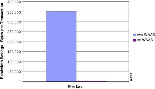
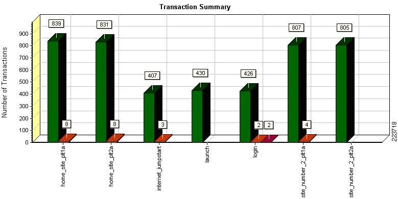
Table 8 Transaction Summary for a 1.544Mbps Circuit Without WAAS
Total Passed: 831
Total Failed: 6
Total Stopped: 37
Figure 23 Transaction Summary for a 1.544Mbps Circuit Without WAAS
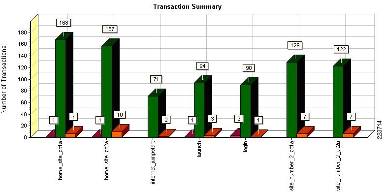
Table 9 Transaction Summary for a 1.544Mbps Circuit With WAAS
Total Passed: 9,008
Total Failed: 2
Total Stopped: 9
Figure 24 Transaction Summary for a 1.544Mbps Circuit With WAAS
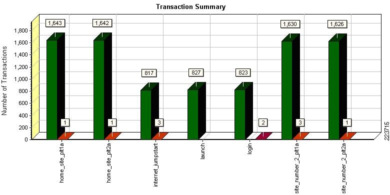
Figure 25 Bandwidth Savings for 512Kbps WAN Link
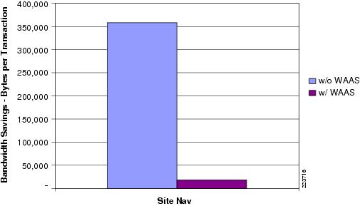
Table 10 Transaction Summary for a 512Kbps Circuit Without WAAS
Total Passed: 271
Total Failed: 14
Total Stopped: 40
Figure 26 Transaction Summary for a 512Kbps Circuit Without WAAS
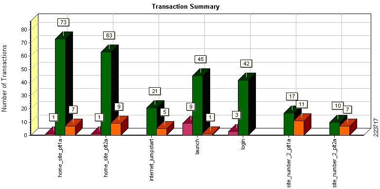
Table 11 Transaction Summary for a 512Kbps Circuit With WAAS
Total Passed: 4,545
Total Failed: 2
Total Stopped: 25
Figure 27 Transaction Summary for a 512Kbps Circuit With WAAS
Appendix D—Network Management
This section focuses on the network management system (NMS) that was used to monitor and provide results indicating the benefits of the Cisco WAAS optimization. The NMS tool used was NetQoS SuperAgent with NetQoS Collector and Reporter. NetQoS Collector gathers the pre-optimized traffic and reports the data to the NetQoS SuperAgent. The NetQoS SuperAgent provides details on the protocols and applications traversing the network(s), including:
•
•
•
•
•
•
•
This information provides the baseline of the application under test with valid overall transaction times (end user experience).
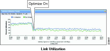
NetQoS Reporter gathers the optimized traffic and reports the data to NetQoS Super Agent. NetQoS Super Agent uses the data from the NetQoS Collector (un-optimized) and compares it to the optimized traffic, indicating the benefits of optimization using the Cisco WAAS as shown in the generic samples in Figure 28, Figure 29, and Figure 30.
Figure 28 Benefit of Optimization Using the Cisco WAAS—Application Response Time
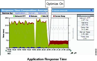
Figure 29 Benefit of Optimization Using the Cisco WAAS—Application Data Rate
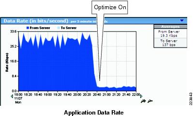
Figure 30 Benefit of Optimization Using the Cisco WAAS—Link Utilization
NetQoS devices passively listen in by using the rspan feature of Cisco routers and switches. They do not poll servers and hence do not add to the server load. For more information about this tool, see:
http://www.netqos.com/CiscoWAASSolutions/Cisco_WAAS_overview.html
Appendix E—References
Enterprise Data Center Wide Area Application Services Design Guide:
http://www.cisco.com/application/pdf/en/us/guest/netsol/ns377/c649/ccmigration_09186a008081c7da.pdf
Cisco Advanced Services
Cisco Services Help Accelerate and Optimize ANS Deployments
Application deployments are complex projects. Cisco Services can help mitigate the risk of making changes to the environment and accelerate deployment of Cisco ANS solutions. Our product and technology expertise is constantly enhanced by hands-on experience with real-life networks and broad exposure to the latest technology and implementations. Cisco uses leading practices to help our customers define their IT and business requirements and help them deliver fast, secure and highly available application access in a scalable environment.
•
•
•
•
•
Cisco ANS Services:
http://www.cisco.com/en/US/products/ps6892/serv_group_home.html
http://www.cisco.com/en/US/products/ps6894/serv_group_home.html
Cisco Validated Design
The Cisco Validated Design Program consists of systems and solutions designed, tested, and documented to facilitate faster, more reliable, and more predictable customer deployments. For more information visit:
http://www.cisco.com/go/validateddesigns
ALL DESIGNS, SPECIFICATIONS, STATEMENTS, INFORMATION, AND RECOMMENDATIONS (COLLECTIVELY, "DESIGNS") IN THIS MANUAL ARE PRESENTED "AS IS," WITH ALL FAULTS. CISCO AND ITS SUPPLIERS DISCLAIM ALL WARRANTIES, INCLUDING, WITHOUT LIMITATION, THE WARRANTY OF MERCHANTABILITY, FITNESS FOR A PARTICULAR PURPOSE AND NONINFRINGEMENT OR ARISING FROM A COURSE OF DEALING, USAGE, OR TRADE PRACTICE. IN NO EVENT SHALL CISCO OR ITS SUPPLIERS BE LIABLE FOR ANY INDIRECT, SPECIAL, CONSEQUENTIAL, OR INCIDENTAL DAMAGES, INCLUDING, WITHOUT LIMITATION, LOST PROFITS OR LOSS OR DAMAGE TO DATA ARISING OUT OF THE USE OR INABILITY TO USE THE DESIGNS, EVEN IF CISCO OR ITS SUPPLIERS HAVE BEEN ADVISED OF THE POSSIBILITY OF SUCH DAMAGES.
THE DESIGNS ARE SUBJECT TO CHANGE WITHOUT NOTICE. USERS ARE SOLELY RESPONSIBLE FOR THEIR APPLICATION OF THE DESIGNS. THE DESIGNS DO NOT CONSTITUTE THE TECHNICAL OR OTHER PROFESSIONAL ADVICE OF CISCO, ITS SUPPLIERS OR PARTNERS. USERS SHOULD CONSULT THEIR OWN TECHNICAL ADVISORS BEFORE IMPLEMENTING THE DESIGNS. RESULTS MAY VARY DEPENDING ON FACTORS NOT TESTED BY CISCO.
CCDE, CCENT, Cisco Eos, Cisco Lumin, Cisco Nexus, Cisco StadiumVision, Cisco TelePresence, the Cisco logo, DCE, and Welcome to the Human Network are trademarks; Changing the Way We Work, Live, Play, and Learn and Cisco Store are service marks; and Access Registrar, Aironet, AsyncOS, Bringing the Meeting To You, Catalyst, CCDA, CCDP, CCIE, CCIP, CCNA, CCNP, CCSP, CCVP, Cisco, the Cisco Certified Internetwork Expert logo, Cisco IOS, Cisco Press, Cisco Systems, Cisco Systems Capital, the Cisco Systems logo, Cisco Unity, Collaboration Without Limitation, EtherFast, EtherSwitch, Event Center, Fast Step, Follow Me Browsing, FormShare, GigaDrive, HomeLink, Internet Quotient, IOS, iPhone, iQ Expertise, the iQ logo, iQ Net Readiness Scorecard, iQuick Study, IronPort, the IronPort logo, LightStream, Linksys, MediaTone, MeetingPlace, MeetingPlace Chime Sound, MGX, Networkers, Networking Academy, Network Registrar, PCNow, PIX, PowerPanels, ProConnect, ScriptShare, SenderBase, SMARTnet, Spectrum Expert, StackWise, The Fastest Way to Increase Your Internet Quotient, TransPath, WebEx, and the WebEx logo are registered trademarks of Cisco Systems, Inc. and/or its affiliates in the United States and certain other countries.
All other trademarks mentioned in this document or Website are the property of their respective owners. The use of the word partner does not imply a partnership relationship between Cisco and any other company. (0807R)
1 Gartner: Server consolidation can save money 12/2005.
 Feedback