-
null
Bias-Free Language
The documentation set for this product strives to use bias-free language. For the purposes of this documentation set, bias-free is defined as language that does not imply discrimination based on age, disability, gender, racial identity, ethnic identity, sexual orientation, socioeconomic status, and intersectionality. Exceptions may be present in the documentation due to language that is hardcoded in the user interfaces of the product software, language used based on RFP documentation, or language that is used by a referenced third-party product. Learn more about how Cisco is using Inclusive Language.
- Updated:
- November 20, 2017
Chapter: Chapter 1 - Introduction
Introduction
Preface
The Cisco Connected Utilities Field Area Network 2.0 Design and Implementation Guide provides a comprehensive explanation of the Cisco Smart Grid Field Area Network system design for Cisco Connected Grid Mesh (CG-Mesh) Advanced Metering Infrastructure (AMI) with the Cisco Industrial Operations Kit (IOK).
The Cisco Connected Utilities Field Area Network 2.0 Design and Implementation Guide includes: information about the system’s architecture, possible deployment models, and guidelines for implementation and configuration. The guide also recommends best practices and potential issues when deploying the reference architecture.
Navigator
Table 1-1 describes the chapters in this document.
|
|
|
|---|---|
Introduction to smart grid concepts, Cisco’s Connected Utilities program, Field Area Network, Advanced Metering Infrastructure, and Cisco Industrial Operations Kit. |
|
Overview of the FAN and the three tiers: Neighborhood Area Network, Wide Area Network, and Energy Operations Center. |
|
Includes the FAN 2.0 system topology and description of the functional components of the solution. It also contains the design specifications and functional description of aspects such as network infrastructure, routing, security, and quality of service QoS) across the FAN tiers. |
|
The Implementation Guide for the FAN 2.0 solution, which includes configuration of the IOK, CG-Mesh, and so on, to implement the solution for AMI with IOK. |
|
This chapter describes the implementation steps and configurations needed to deploy the end-to-end IOK AMI solution using the recommended reference topology. |
|
Chapter 6, “Service Deployment for SAToP with Alstom Relays” |
|
Executive Summary
Smart Grid Overview
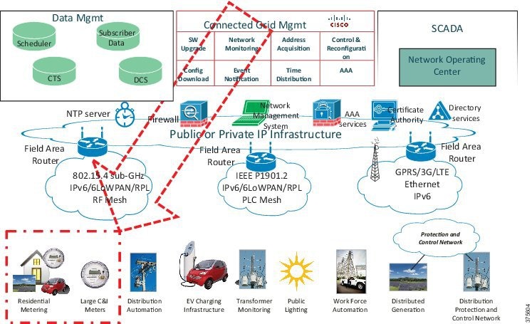
Figure 1-1 Smart Grid Ecosystem
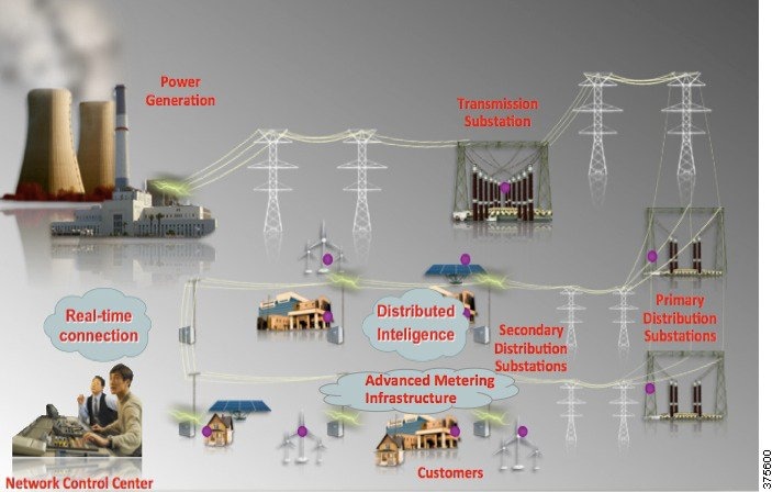
The smart grid is a combination of the electric power grid and the associated information and communications technology (ICT) designed to efficiently delivering sustainable, economic, and secure electricity supplies. This renders the power delivery chain observable, controllable, automated, and integrated, thus providing complete awareness and control of the grid state, the ability to adapt to rapidly changing conditions without human intervention where possible, and enabling the interaction of the grid devices, systems, and business processes to yield the optimal business value.
Some of the smart grid applications are intelligent transmission and distribution, distributed generation, distribution automation, advanced metering infrastructure, and demand response. This document addresses the advanced metering infrastructure in particular.
Figure 1-1 depicts the major components of the smart grid ecosystem, from the power generation center up to the customers, along with the network control center, which provides a monitoring and control system for the smart grid. Electric energy is transported on high-voltage lines since the line losses are much smaller than with low-voltage lines. Grid architectures in Europe and other parts of the world have secondary substations that condition the power from medium voltage (1000V to 35kV) to low voltage (up to 1000V) for use by homes and businesses. These substation huts can be located underground or above ground and, in some instances, on pole tops. In North America, the pole-top transformer is used to condition the power for consumer or commercial use.
Cisco Connected Utilities
The Cisco Connected Utilities program brings together IP-based solutions to cater to the growing needs of the energy industry. These solutions are secure, scalable, and flexible, are based on open standards, and aim to accommodate multiple services by leveraging common infrastructure.
The energy industry is rapidly evolving in size and complexity. Utilities are now focused on grid modernization to optimize the power supply chain. Smart meters, grid sensors, advanced distribution automation, substation automation, wide area measurements, etc. are proliferating in this area, typically known as operational technology (OT). The Cisco Smart Grid solution enables grid modernization and maximizes business outcomes by providing an end-to-end, IP-based reference architecture—from data centers responsible for grid operations to homes and industries. Information technology integrates with the Operations Technology of the utilities to manage these complex advanced systems while meeting security and regulatory requirements.
Substation Automation and Field Area Networks (FANs) are the two programs under Cisco Connected Utilities. This document is the Cisco Validated Design (CVD) for Field Area Network 2.0; a separate CVD for Substation Automation 2.0 is available.
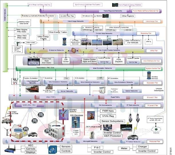
The Cisco Grid Blocks architecture (as depicted in Figure 1-2) provides a framework for integrating the end-to-end electrical grid to deliver a highly secure and reliable communications infrastructure. This modular approach allows projects to be implemented over time, leveraging existing infrastructure, while building toward a strategic, forward-looking architecture. Each grid block module offers specific design guidance for deploying applications and solutions as a part of a grid modernization roadmap.
This document provides the design and implementation guidelines for urban and rural FANs and for residential and commercial Neighborhood Area Networks (indicated in red).
Figure 1-2 Cisco Smart Grid Reference Model
Multi-Services Field Area Network
Figure 1-3 Field Area Network Overview
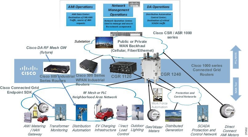
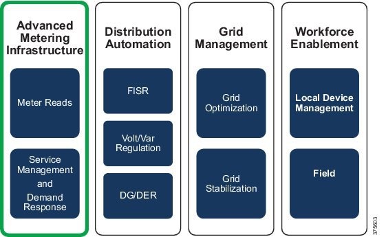
The Field Area Network (FAN) is the communication network overlay for the electric distribution grid (as shown in Figure 1-3). The Cisco vision for the smart grid multi-services Field Area Network (FAN) is to help enable pervasive monitoring and control of energy distribution networks to enhance energy delivery. The Cisco multi-services FAN solution is based on a flexible two-tier architecture that provides IP network services such as security, quality of service, resilience, and management. When deployed, the Cisco FAN network is capable of supporting use cases such as Advanced Metering Infrastructure, Distribution Automation, work force automation, Electric Vehicles, Distributed Generation and Storage, and Street Lighting (see Figure 1-4). This document provides the design and implementation guidelines for the Advanced Metering Infrastructure in particular.
Figure 1-4 Multi-Services FAN Model
The two-tier FAN architecture (as represented in Figure 1-3) that provides the communication network for the Smart Grid consists of the following:
- The Neighborhood Area Network (NAN) that interconnects a range of devices such as smart meters, streetlights, or DA devices to a series of Field Area Routers on an RF mesh, PLC network, Ethernet, or serial interfaces such as RS232 and RS485.
- A Wide Area Network (WAN) that connects the Field Area Routers to the Energy Operations Center (EOC), either directly or through the substation network infrastructure.
The two tiers act as backhaul networks for a variety of other electric grid control devices, multi-tenant services (gas and water meters), and optionally data exchanges to home area network (HAN) devices.
Cisco’s FAN portfolio consists of the pole-top and DIN-rail mounted dual-stack Cisco 1000 Series Connected Grid Routers and the Connected Grid RF Mesh and PLC Mesh standards-based IPv6 reference designs to enable large scale IP connectivity for devices such as smart meters, sensors, and EV charging stations. Cisco also provides a comprehensive Connected Grid Security and Network Management Platform for providing a single end-to-end view of the IP network that can scale to millions of devices.
With the introduction of the IR509, IR809, and IR829 series Industrial Routers, the Cisco FAN solution is extended to Distribution Automation. Grid architectures in Europe and other parts of the world have secondary substations that condition the power from medium to low voltage for use by homes and businesses. These substation huts can be located underground or above ground, and in some instances, on pole tops. In these cases, the IR509, IR809, or IR829 serves as multi-service WAN router in a secondary substation to connect RTU/SCADA, concentrate metering communication, and connect to Volt/VAR controllers. However, the CG-Mesh is currently available for the 902-928MHz band (and its subsets) only, therefore the countries where the band cannot be used are outside the scope of the IR509 and CG-Mesh usage.
Field Area Networks are often closed, proprietary systems that generally support just a single service. As a result, they do not support interoperability across multiple vendors or take advantage of the decades of networking expertise available within the Internet Protocol suite.
The Wi-SUN ® Alliance is a global ecosystem of organizations creating interoperable wireless solutions for use in energy management and smart-utility network applications. Cisco supports the Wi-SUN alliance and is certified for the Wi-SUN 1.0 PHY profile.
The Wi-SUN defined Field Area Network is based upon the IP Protocol suite, with the initial release based on IEEE 802.15.4g PHY and 802.15.4e MAC wireless mesh technologies. Usage of the IP protocol suite provides many benefits, including the ability to support additional PHY/MAC technologies in the future.
By supporting Wi-SUN, Cisco will help drive the technical definition for standards based, multi-service, secure, and scalable Field Area Networks.
Advanced Metering Infrastructure
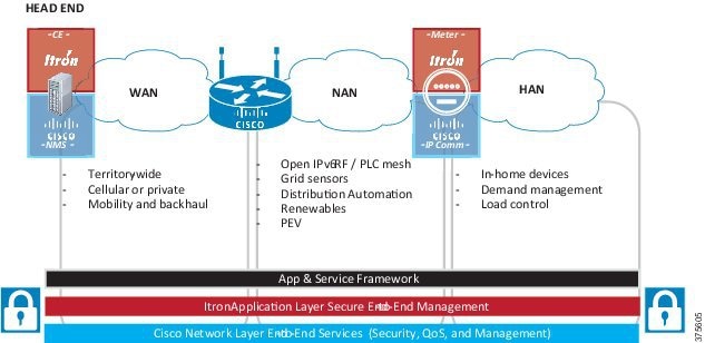
Advanced Metering Infrastructure (AMI) is the architecture for an automated, two-way communication system between a smart meter and a utility’s operational technology (OT) network. Figure 1-5 shows an overview of the AMI.
AMI is an important part of any smart grid initiative. This enables the utility to obtain real-time data about power consumption and allows customers to make informed choices about energy usage based on the price at the time of use.
Figure 1-5 AMI Services in the FAN Ecosystem
Cisco has the following two solution offerings to achieve AMI functionality:
- A full scale head-end solution that can scale to millions of end-points such as smart meters.
- A small-scale, virtual head-end solution that dramatically reduces the cost, time, and complexity of head-end deployment with a pre-packaged software bundle, ideal for proof of concepts, pilot, small scale, or router-only deployments. This solution uses the Cisco Industrial Operations Kit (IOK) to provide the head-end functionality.

Note![]() This document contains the design and implementation guide for the latter.
This document contains the design and implementation guide for the latter.
Cisco collaborates with industry partners to develop solutions that integrate with Connected Grid architectures to support advanced smart grid capabilities. Devnet partners for Cisco-enabled grid endpoints include IPenable, Itron, EDMI, I-Dutto, WEG Industries, EM-Lite, Cooper Power Systems, Sistemas Tecnicos Digitais, Kamstrup, FITEC, Tatung, Incotex, Vision Metering, Elster, Grid-Sentry, GAS Sentinel, ICIL, M2M Telemetria, Tollgrade, QinetiQ, and Sentient Energy. The design specified in this document is validated with Itron Centron OpenWay Smart Meters powered by the Cisco IP communication stack and the Itron OpenWay Collection Engine for AMI application management.
Figure 1-6 Advanced Metering Infrastructure Overview
The goal of AMI is to provide a means to achieve two-way communication between a smart meter and the utility network. This enables the utility to obtain real-time data about power consumption and allows customers to make informed choices about energy usage based on the price at the time of use. A smart meter is different from a legacy meter in that it is capable of two-way communication and is typically reachable by IP.
Meter data reading is one of the primary applications of AMI. The following are typical AMI functions:
- Over the air firmware upgrades for meters.
- Remote connect and disconnect of power from meter to load.
- Power Outage Notification (PON) and Power Notification Restoration (PNR) messages from meters and the Field Area Routers (FARs).
- Tamper notification messages from the meters.
- Demand Response and Pricing messages for Home Area Network (HAN) devices behind the meter, such as in-home displays, thermostats, HVAC/Water Heater/Pool Pump controllers, and so on.
- Network management tools for troubleshooting, such as ping and traceroute.
- Network device communications status and statistics.
- Transport network control plane messages necessary for timing distribution, neighbor discovery, IP routing updates, and so on.
The architecture provides network functionality necessary to meet the above requirements by ensuring two-way communication between the smart meters and the head-end systems.
The architecture defines a network infrastructure on which other services such as Distribution Automation and workforce management can be built, the design of which will be added in this CVD at a later stage.
The Cisco Industrial Operations Kit
The Cisco Industrial Operations Kit (IOK) is a software solution designed to simplify and accelerate the setup of a field area network. The Cisco IOK is a fully virtualized head-end in a box which incorporates multiple virtual appliances for management and security enforcement and other head-end services for the Cisco Internet of Things (IoT) Network solution.
In the Cisco Industrial Operations Kit, multiple systems exist as individual virtual machines within a single physical server such as the Cisco Unified Computing System (UCS). Pre-tested orchestration scripts shipped with the kit enable easy provisioning of the virtual machines. IOK also simplifies zero touch deployment (ZTD) offered by the connected grid management system, namely the Cisco IoT Field Network Director, by configuring routers with pre-ZTD configuration. The setup is further simplified with the predefined configuration template and the orchestrator provides management of the complete infrastructure.
The solution is suitable and cost-effective for small scale and pilot deployments of up to 1,000 routers and 250,000 end points. It is ideal for customers looking to pilot a completely capable field area deployment. It supports IoT field network solutions and routers, such as the Cisco 1000 Series CGR, Cisco 819 hardened Integrated Services Router, and the Cisco 500 Series Wireless Personal Area Network (WPAN) Industrial Routers (IR 500).
However, it must be noted that the IOK does not support high availability of the head-end systems, such as the Field Network Director, which is the network management system.
Due to such limitations, it is recommended that the IOK not be deployed in production environments. The kit may be used to provide proof of concepts of a functional head-end that delivers AMI capabilities, with a relatively faster time to install and ease of deployment.
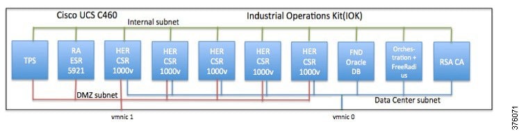
The following are the components of the Cisco Industrial Operations Kit:
- Cisco IoT Field Network director with Oracle database
- Head-end routers based on Cloud Services Router (CSR) 1000V
- Registration authority based on Cisco Embedded Series Router (ESR) 5921
- Tunnel Provisioning Server
- RSA-based Certificate Authority
- Orchestrator with FreeRADIUS
Figure 1-7 Virtual Machines in the Cisco Industrial Operations Kit
Updates in FAN 2.0
The Cisco FAN 1.0 solution was released as the Cisco Smart Grid Multi-Services Field Area Network (FAN) Design Implementation Guide, which included AMI and DA use cases.
The FAN 2.0 solution will upgrade the FAN 1.0 AMI use case with new solution components, including the Cisco 1000 Series CGR running Cisco IOS, Field Network Director (FND) 3.0, and integrated head-end Industrial Operations Kit (IOK) 2.0.
Subsequent releases will upgrade the Distribution Automation use case with IR509, IR809, and IR829 routers for secondary substations. Future releases will cover 800 MHz RF mesh and IEEE 1901.2 PLC technologies when these technologies are made available.
Business Drivers and Benefits
Utilities are faced with a number of challenges with the production and distribution of energy. The challenges driving the need for a smart grid are efficiency of electric transmission on the grid, grid security, compliance with government regulations such as North American Electric Reliability Corporation (NERC), aging workforce, costly peak load management, lack of visibility into the grid, and manual grid operations such as handling power outages.
Cisco’s vision in the smart grid ecosystem entails IP networks for end-to-end smart grid communication. The key benefits include reduced operations expense, improved grid security, reduced capital expense, and regulatory compliance.
The benefits of virtualization of the head-end design are multifold. Operation costs are dramatically decreased due to the reduced cost of deployment, as the entire functionality of the energy operations center’s head-end systems are made available from a single server, such as the Cisco Unified Computing System. The simplified head-end design provides reduced time for installations. The utility can thus have quicker time to deployment of a field area network with fewer skilled personnel.
 Feedback