-
null
Bias-Free Language
The documentation set for this product strives to use bias-free language. For the purposes of this documentation set, bias-free is defined as language that does not imply discrimination based on age, disability, gender, racial identity, ethnic identity, sexual orientation, socioeconomic status, and intersectionality. Exceptions may be present in the documentation due to language that is hardcoded in the user interfaces of the product software, language used based on RFP documentation, or language that is used by a referenced third-party product. Learn more about how Cisco is using Inclusive Language.
- Updated:
- November 20, 2017
Chapter: Chapter 6 - Service Deployment for SAToP with Alstom Relays
- Alstom
- SAToP Circuit Overview
- Using IOS CLI for Provisioning Relay Connectivity over SAToP
- Using IOS CLI to Validate Relay Connectivity over SAToP
- Using NMS for Provisioning Relay Connectivity over SAToP
- Configuration Collection in Cisco Prime Provisioning
- MPLS-TP Discovery in Cisco Prime Provisioning
- Confirm Status of Last Task
- Create a CEM CLASS with Dejitter Buffer of 2 and 46 Byte Payload
- Create a TP Tunnel Interface
- Create a Pseudowire Class that Uses the TP Tunnel (Tunnel-tp0)
- Create a Teleprotection Policy
- Commissioning the Service on a New E1 CEM Interface
Alstom
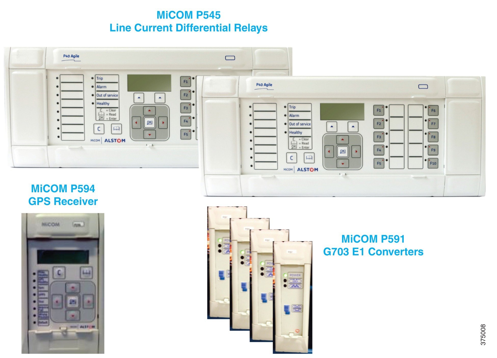
Alstom P545 Line Differential Relays Overview
Figure 6-1 illustrates the components of the Alstom Line Differential Relay solution.
Figure 6-1 Alstom P545 Line Differential Relays
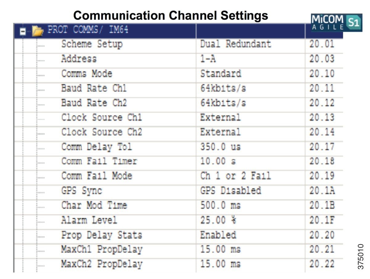
Alstom Relay Settings
Figure 6-2 and Figure 6-3 illustrate the settings applied to the Alstom Line Differential Relay solution.
Figure 6-2 Alstom Relay Settings—1
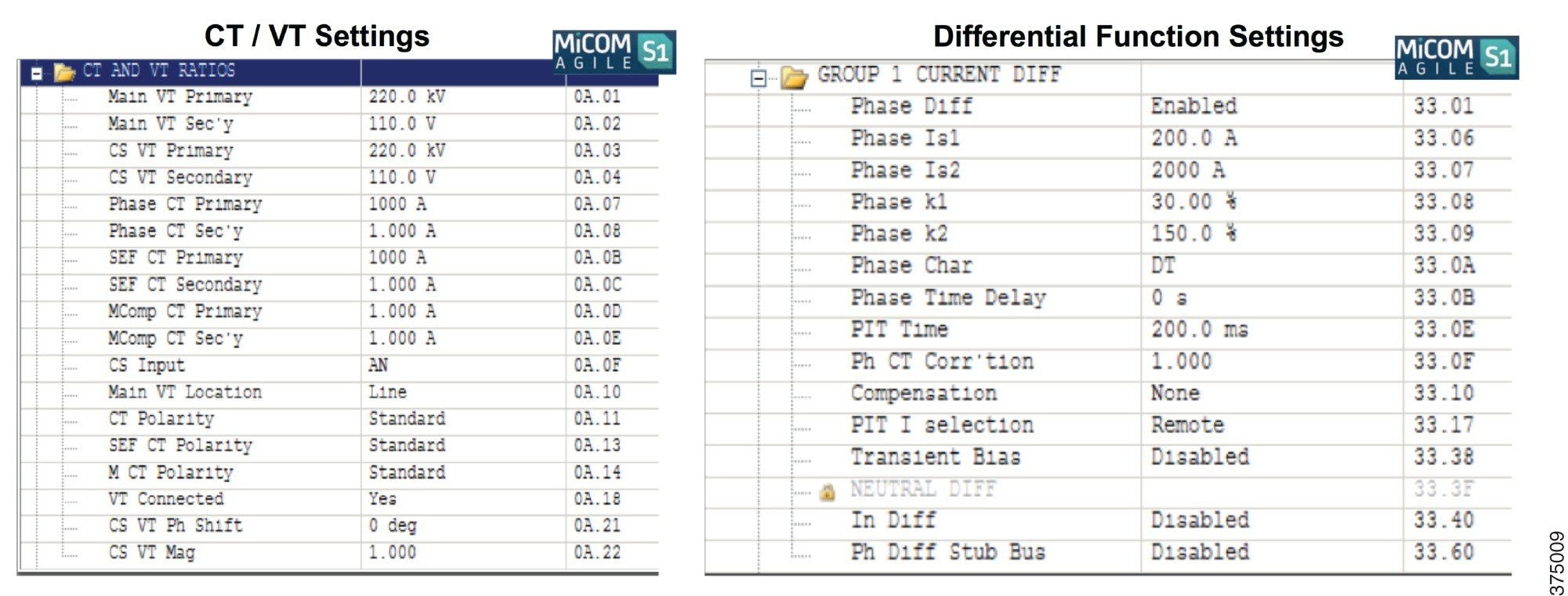
Figure 6-3 Alstom Relay Settings—2
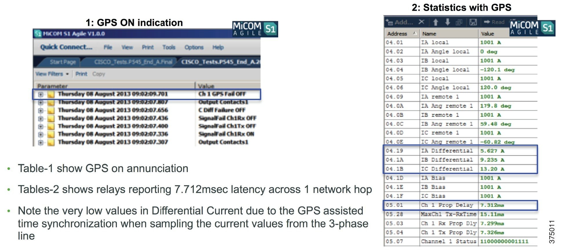
Alstom Relay Status with GPS Assist
Figure 6-4 illustrates the behavior of the Alstom Line Differential Relay solution when GPS is available.
Figure 6-4 Alstom Relay Status with GPS Assist
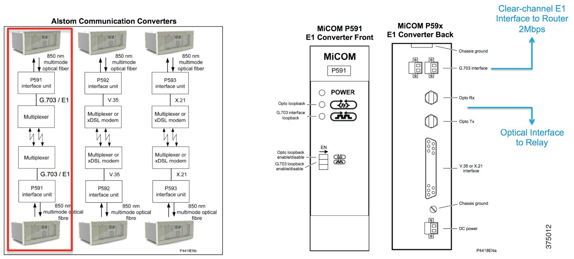
Alstom E1/T1 Converters
Figure 6-5 illustrates the various converters available for the Alstom Line Differential Relay solution.
Figure 6-5 Alstom E1/T1 Converters
Special Considerations
The TDM circuit emulation pseudowire employs a de-jitter buffer to compensate for the network Packet Delay Variation (PDV).

Note The ASR900 de-jitter buffer is configurable between 1-500msec. There is a trade-off between de-jitter buffer and latency. A large de- jitter buffer will impact the end-to-end latency of the protection scheme, and therefore its size must be optimally tuned to smooth out network PDV to maintain TDM line synchronization and not more.
SAToP Circuit Overview
Alstom Relay Clear Channel E1 Protection
The data rate from Alstom relays over the optical interface is 64kbps. Alstom Serial Converters convert the 64kbps optical signal into a 2 Mbps E1 clear-channel signal.
ASR900 substation routers enable circuit emulation for transporting E1 relay telegrams to the remote end using a SAToP pseudowire over MPLS/IP. The SAToP pseudowire de-jitter buffer is configured at 1msec. See Figure 6-6.
Figure 6-6 SAToP Circuit Overview

ASR900 substation routers are frequency synchronized for TDM circuit emulation using SyncE. The pseudowire traffic is carried over MPLS-TE tunnels using explicit routing or MPLS-TP tunnels to ensure symmetrical forward and return paths.
TE-FRR protection is used to achieve 50ms recovery against failures in the transport network.
Alstom Latency
The primary MPLS label switched path traverses a direct link between the two ASR900s.The backup MPLS label switched path traverses 5 ASR900 routers. Latency delta between 1-hop and 5-hops is only 83usec due to ASR900 centralized architecture and Cisco low-latency ASIC.
Note Latency numbers reflected here do not account for distances between substations. Add 1msec propagation delay (speed of light through fiber optic) for every 200km between substations.
Using IOS CLI for Provisioning Relay Connectivity over SAToP
MPLS-TP Tunnel Endpoints
Configure MPLS-TP Tunnel Endpoints. The following is a sample endpoint configuration on the ASR902-W2413:
The following is a sample endpoint configuration on the ASR903-W2504:
MPLS-TP Tunnel Midpoints
Configure MPLS-TP LSP at midpoint routers. In the bottom ring in the system topology, the following router midpoints need configuration:
Using IOS CLI to Validate Relay Connectivity over SAToP
Validate MPLS PW Circuit Emulation
The following verifications are made when the short path (MPLS-TP working path) is ACTIVE:
Legend: XC ST=Xconnect State S1=Segment1 State S2=Segment2 State UP=Up DN=Down AD=Admin Down IA=Inactive SB=Standby HS=Hot Standby RV=Recovering NH=No Hardware
XC ST Segment 1 S1 Segment 2 S2 ------+---------------------------------+--+---------------------------------+--
The following verifications are made when the long path (MPLS-TP protect path) is ACTIVE:
Legend: XC ST=Xconnect State S1=Segment1 State S2=Segment2 State UP=Up DN=Down AD=Admin Down IA=Inactive SB=Standby HS=Hot Standby RV=Recovering NH=No Hardware
Using NMS for Provisioning Relay Connectivity over SAToP
Configuration Collection in Cisco Prime Provisioning
Complete the following steps to run a configuration collection on all routers through which an MPLS-TP tunnel will traverse (all midpoints and endpoints) in Cisco Prime Provisioning:
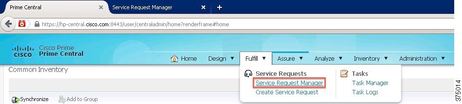
Step 1 Launch Prime Provisioning from Cisco Prime Central’s Fulfill – Service Request Manager menu, as shown in Figure 6-7.
Figure 6-7 Launch Cisco Prime Provisioning
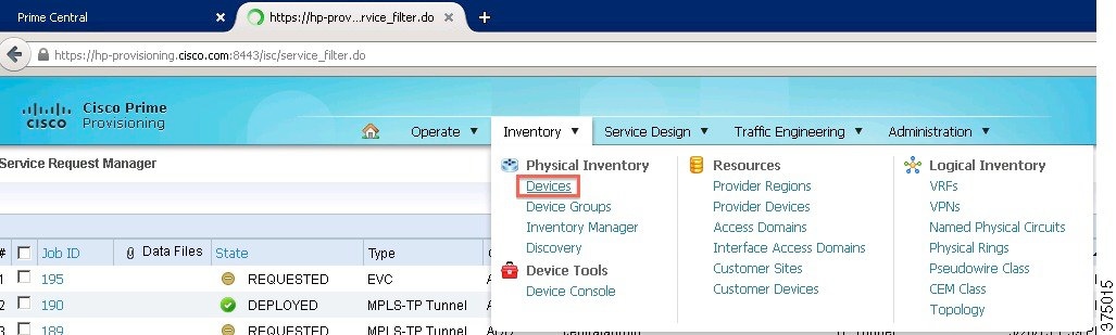
Step 2 Select Devices from Inventory - Physical Inventory – Devices, as shown in Figure 6-8.
Figure 6-8 Cisco Prime Provisioning Select Devices
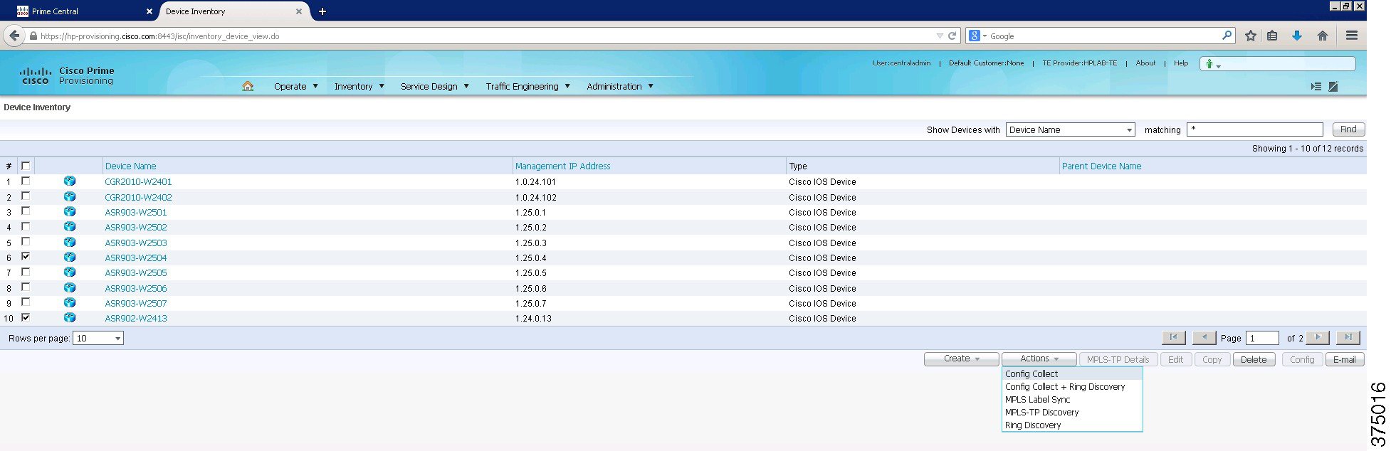
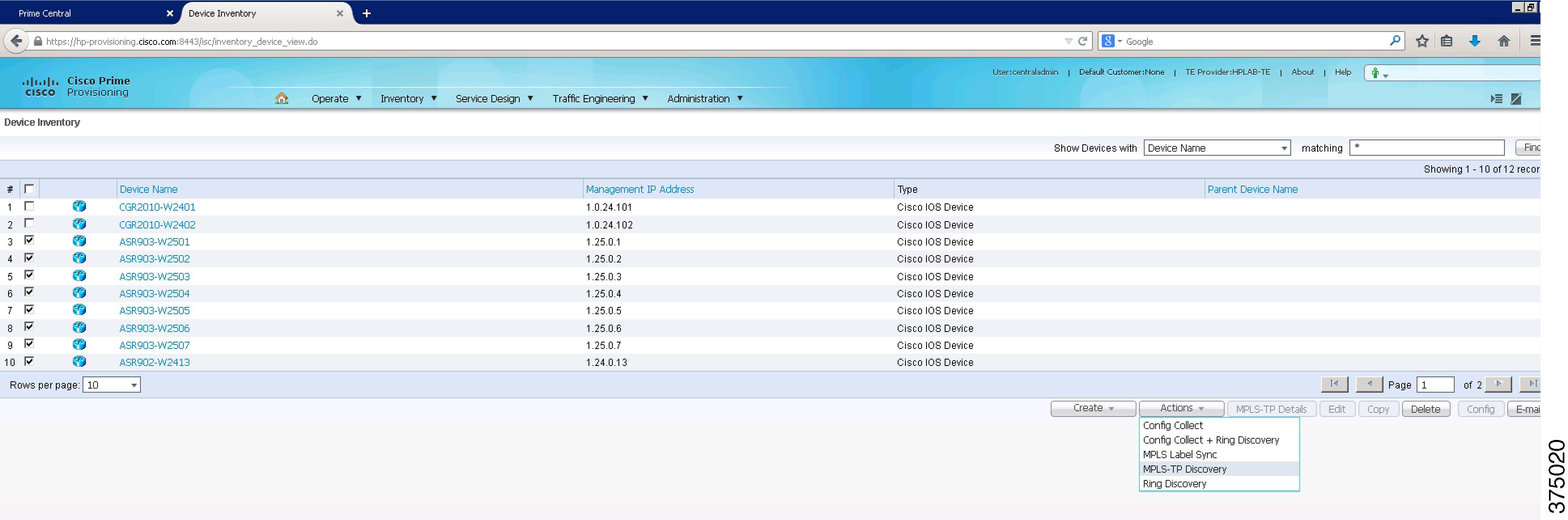
Step 3 Select Device(s) and go to Actions - Config Collect, as shown in Figure 6-9.
Figure 6-9 Cisco Prime Provisioning Configuration Collection
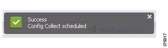
Step 4 Once the configuration collection is scheduled, you should receive a Success message, as shown in Figure 6-10.
Figure 6-10 Cisco Prime Provisioning—Configuration Collection Success
MPLS-TP Discovery in Cisco Prime Provisioning
In Cisco Prime Provisioning, complete the following steps to run an MPLS-TP discovery on all routers through which an MPLS-TP tunnel will traverse (all midpoints and endpoints):
Step 1 Launch Prime Provisioning from the Fulfill – Service Request Manager menus in Prime Central, as shown in Figure 6-11.
Figure 6-11 Launch Cisco Prome Provisioning

Step 2 Select Devices from Inventory - Physical Inventory – Devices, as shown in Figure 6-12.
Figure 6-12 Cisco Prime Provisioning Devices

Step 3 Select Device(s) and go to Actions - MPLS-TP Discovery, as shown in Figure 6-13.
Figure 6-13 Cisco Prime Provisioning MPLS-TP Discovery
Confirm Status of Last Task
After running a configuration collection and MPLS-TP discovery, you can confirm the status of these or any other tasks by completing the following steps:
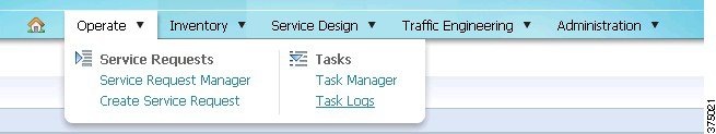
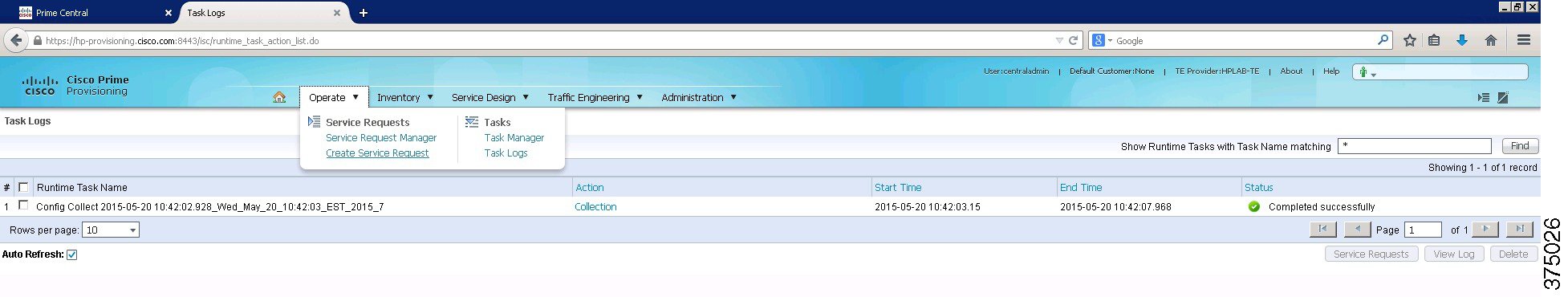
Step 1 Select Operate – Tasks - Task Logs, as shown in Figure 6-14.
Figure 6-14 Cisco Prime Provisioning Task Logs
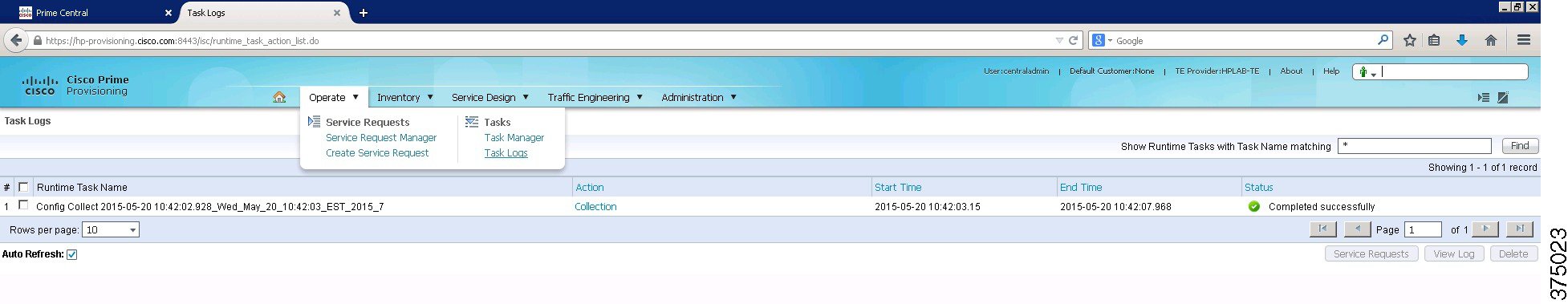
Step 2 Look under the last column for status of the operation, as shown in Figure 6-15.
Figure 6-15 Cisco Prime Provisioning Task Status
Create a CEM CLASS with Dejitter Buffer of 2 and 46 Byte Payload
To create a CEM CLASS with dejitter buffer of 2 and 46 byte payload, complete the following steps:
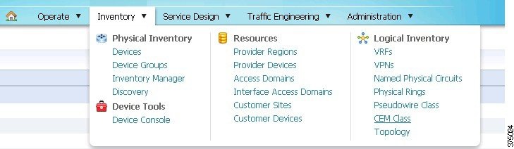
Step 1 Select Inventory - Logical Inventory - CEM Class, as shown in Figure 6-16.
Figure 6-16 Cisco Prime Provisioning CEM Class
Step 2 Click the Create button and the new CEM class window opens up, as shown in Figure 6-17.
Figure 6-17 Cisco Prime Provisioning New CEM Class from SAToP
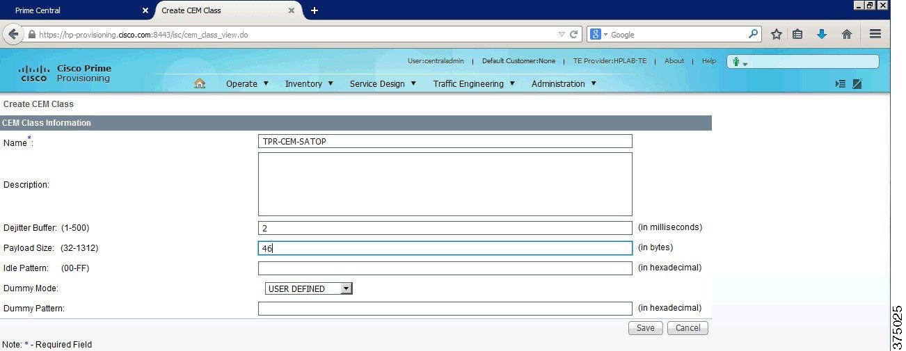
Step 3 Click Save when finished.
Create a TP Tunnel Interface
To create a TP Tunnel interface, compete the following steps:
Step 1 Starting from Cisco Prime Provisioning, select Operate – Service Requests – Create Service Request, as shown in Figure 6-18.
Figure 6-18 Cisco Prime Provisioning Create a Service Request
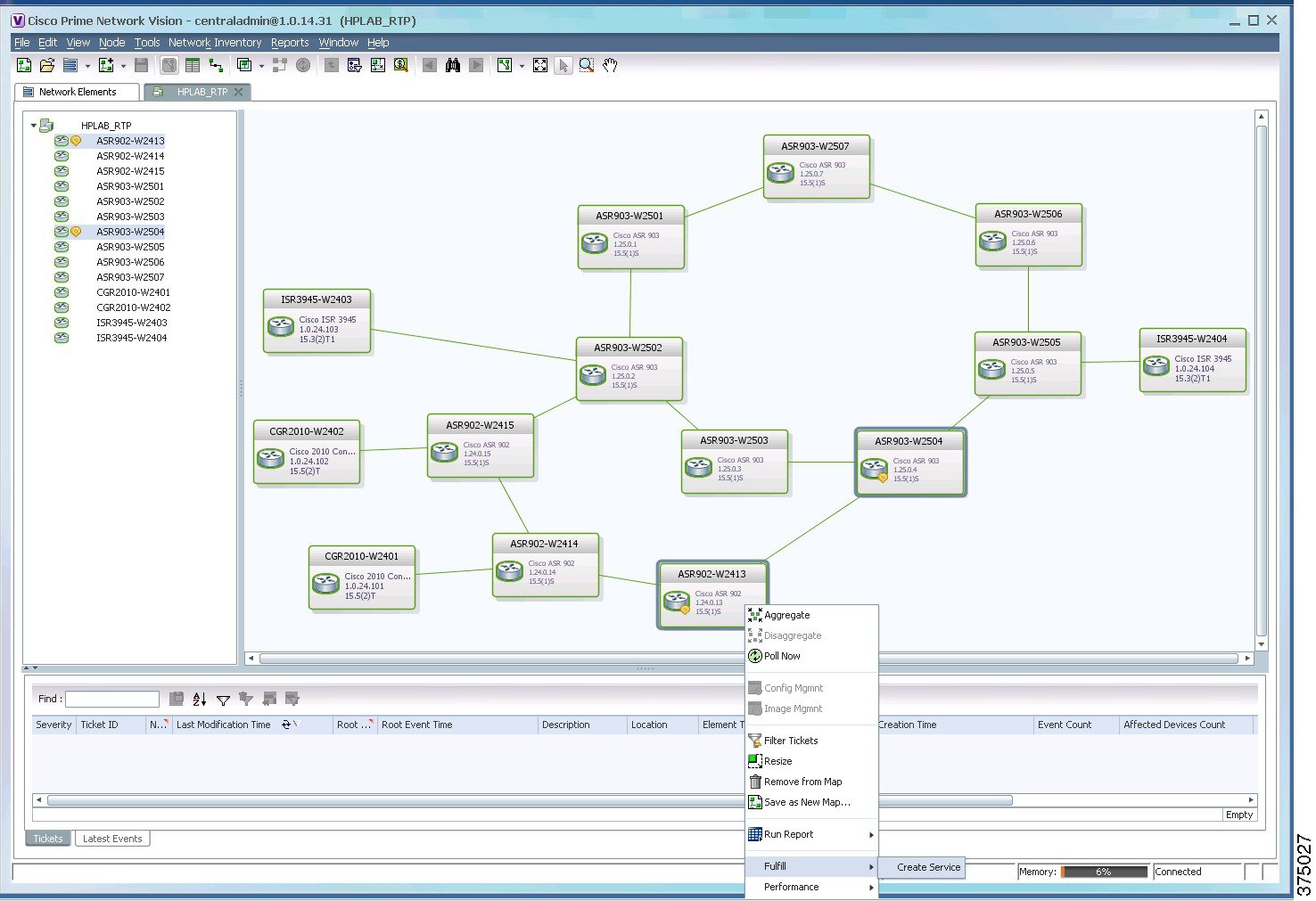
You can also start from Cisco Prime Network Vision, by selecting the TP tunnel endpoints, right-clicking, and choosing Fulfill – Create Service, as shown in Figure 6-19.
Figure 6-19 Prime Network Create a Service Request
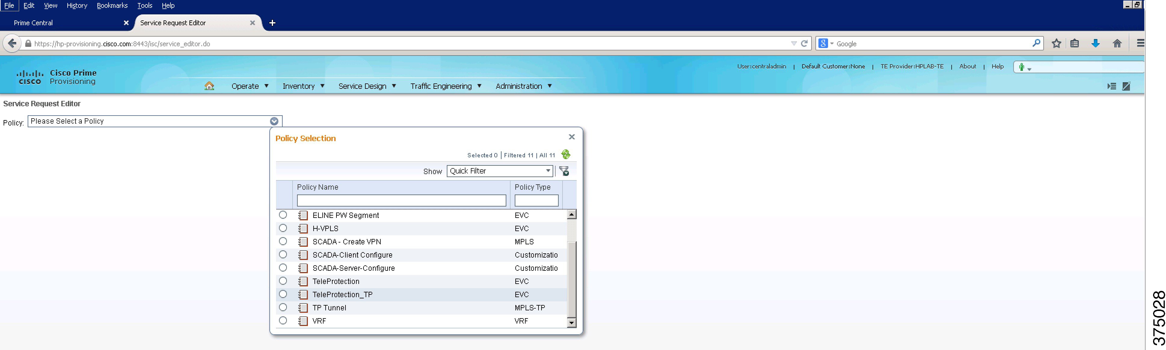
Step 2 Select the policy TP Tunnel (MPLS-TP policy type), as shown in Figure 6-20.
Figure 6-20 TP Tunnel Service Request—1
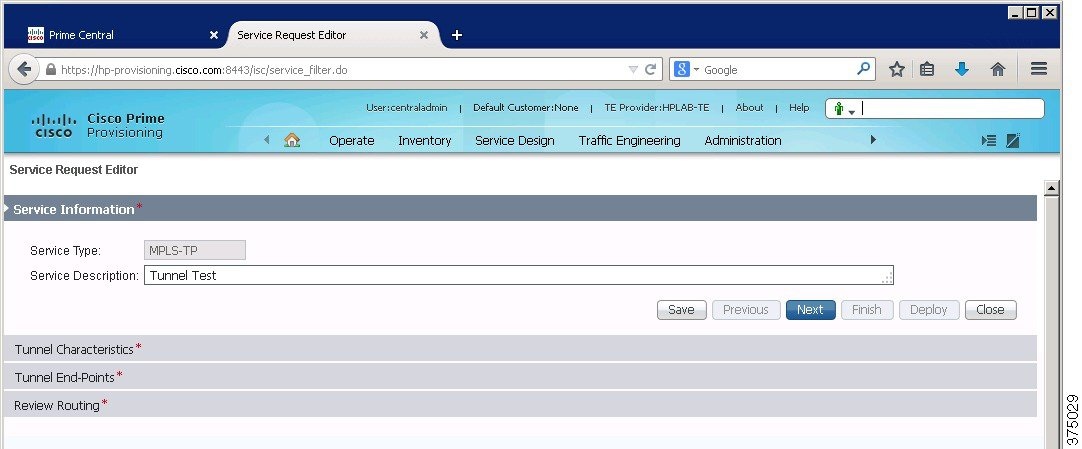
Step 3 Enter the service description and click Next, as shown in Figure 6-21.
Figure 6-21 TP Tunnel Service Request—2
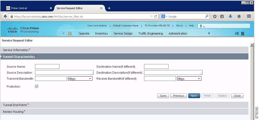
Step 4 Enter relevant information around the tunnel characteristics and click Next, as shown in Figure 6-22.
Figure 6-22 TP Tunnel Service Request—3
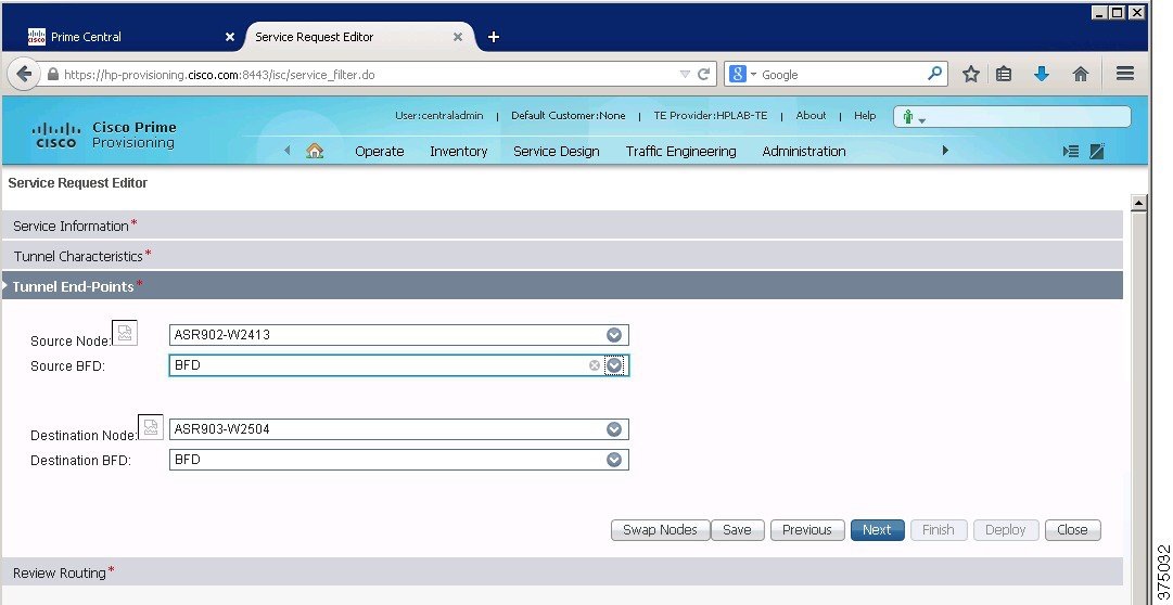
Step 5 Enter relevant information around the tunnel end points and click Next , as shown in Figure 6-23.
Figure 6-23 TP Tunnel Service Request—4
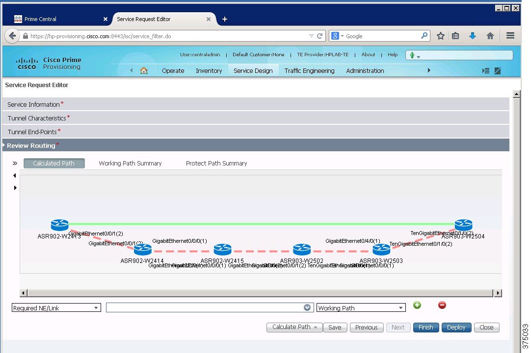
Step 6 Review routing information about the calculated path, as shown in Figure 6-24.
Figure 6-24 TP Tunnel Service Request—5
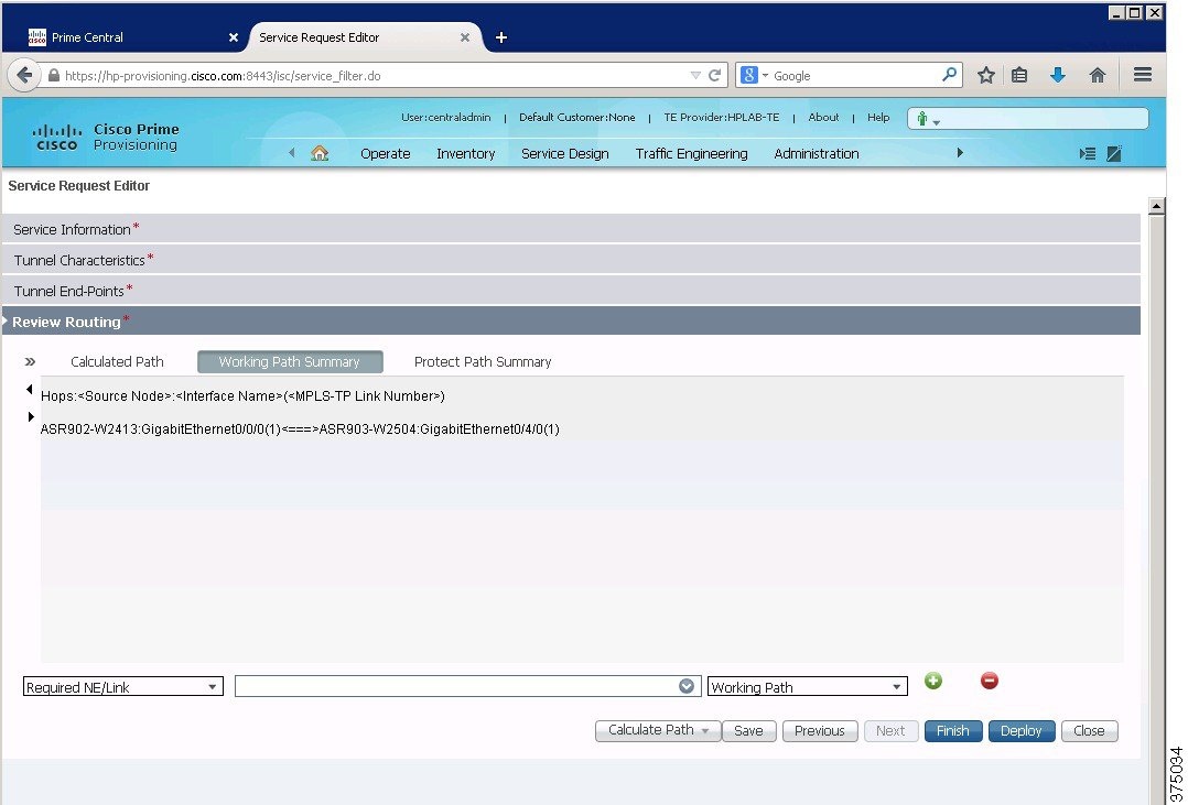
Step 7 Review routing information about the working path, as shown in Figure 6-25.
Figure 6-25 TP Tunnel Service Request—6
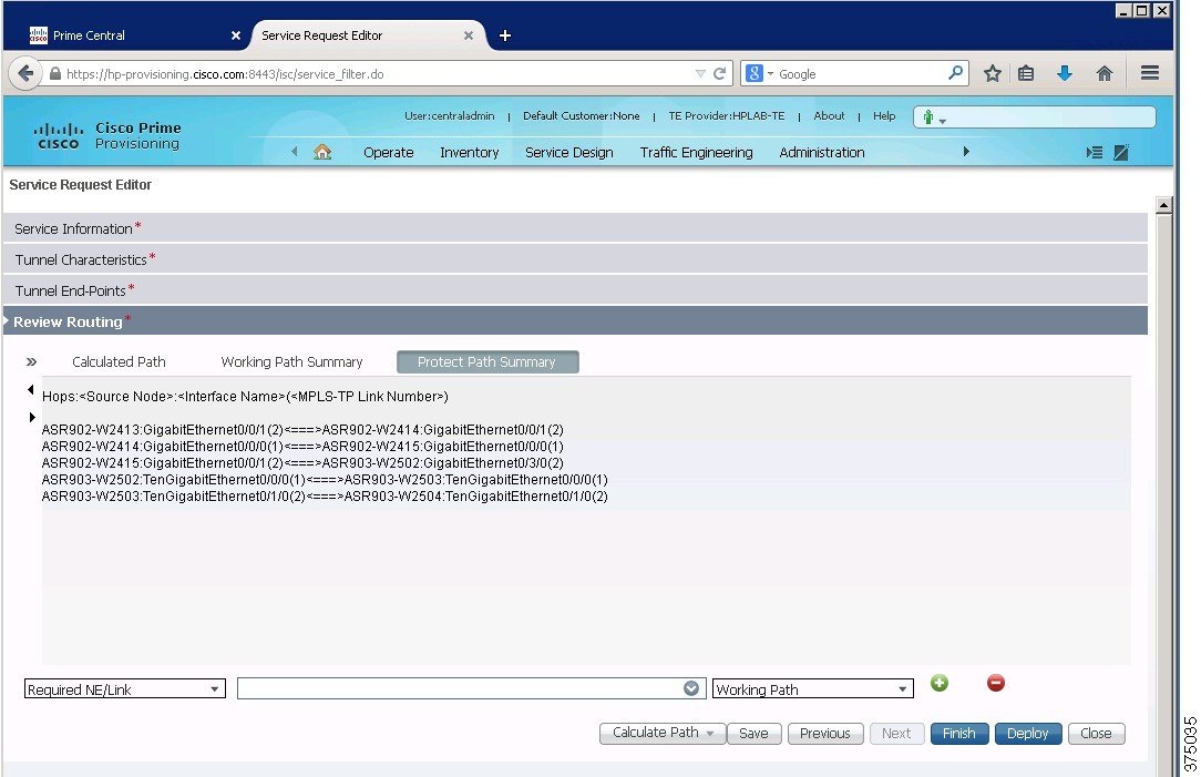
Step 8 Review routing information about the protect path and click Finish, as shown in Figure 6-26.
Figure 6-26 TP Tunnel Service Request—7
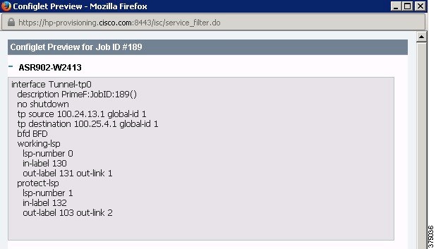
Step 9 An MPLS-TP tunnel endpoint configuration preview is shown in Figure 6-27.
Figure 6-27 TP Tunnel Service Request—8
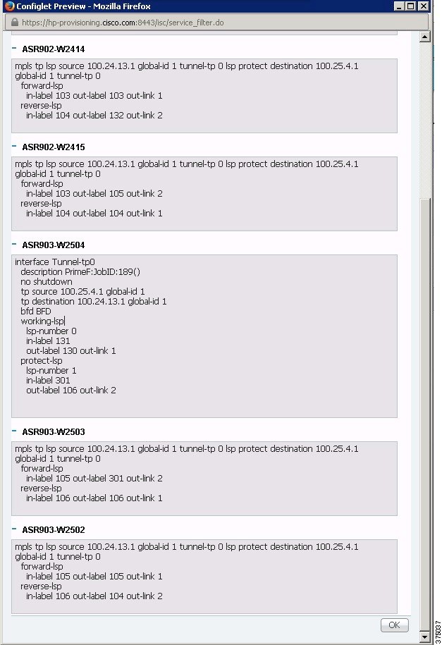
Step 10 An MPLS-TP tunnel midpoint configuration preview is shown in Figure 6-28.
Figure 6-28 TP Tunnel Service Request—9
Step 11 Once you deploy the service, check the status to confirm deployment by selecting Operate – Service Requests – Service Request Manager, as shown in Figure 6-29.
Figure 6-29 Cisco Prime Provisioning Service Request Manager
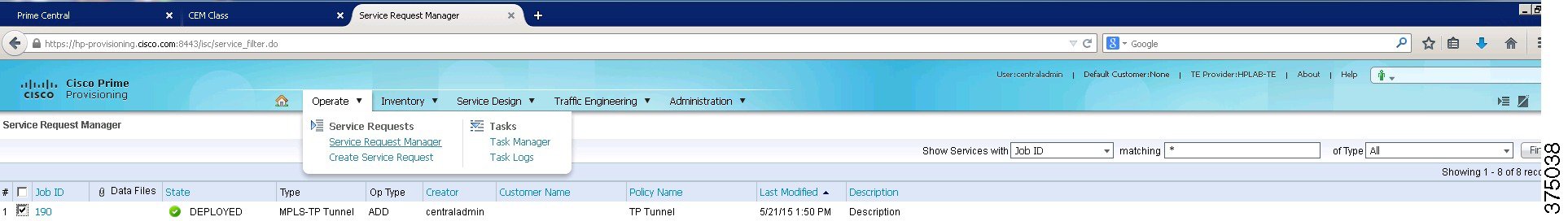
Note The MPLS-TP tunnel number for future use. In the screenshots above, the TP tunnel number is 0.
Create a Pseudowire Class that Uses the TP Tunnel (Tunnel-tp0)
To create a pseudowire class that uses the TP tunnel (Tunnel-tp0), complete the following steps:
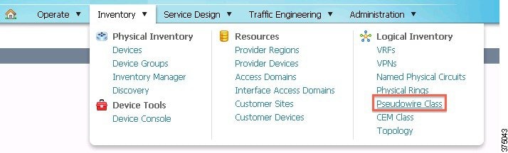
Step 1 Select Inventory - Logical Inventory - Pseudowire Class, as shown in Figure 6-30.
Figure 6-30 Cisco Prime Provisioning Pseudowire Classes
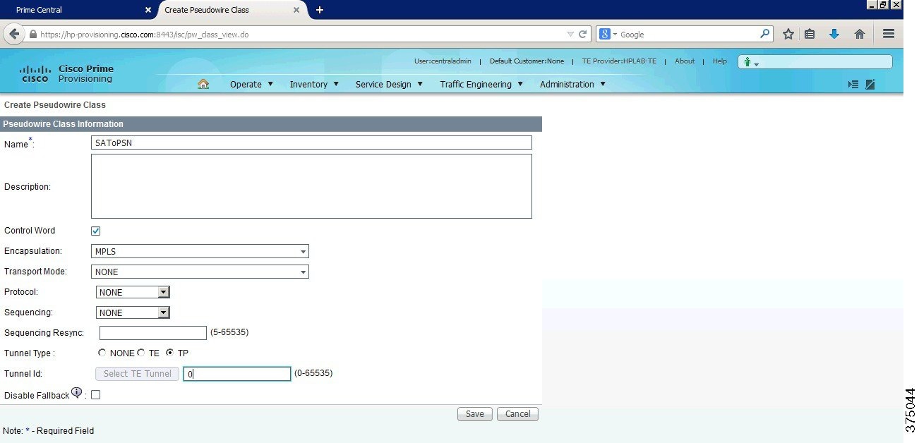
Step 2 Fill in the information, as shown in Figure 6-31.
Figure 6-31 Cisco Prime Provisioning Pseudowire Class Creation
Create a Teleprotection Policy
To create a teleprotection policy, complete the following steps:
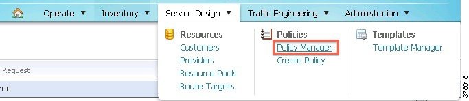
Step 1 Select Service Design - Policies - Policy Manager, as shown in Figure 6-32.
Figure 6-32 Cisco Prime Provisioning Policy Manager
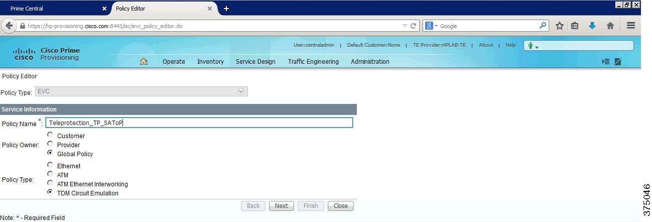
Step 2 Fill in basic service information, including the name of the policy, as shown in Figure 6-33.
Figure 6-33 Cisco Prime Provisioning New Policy—1
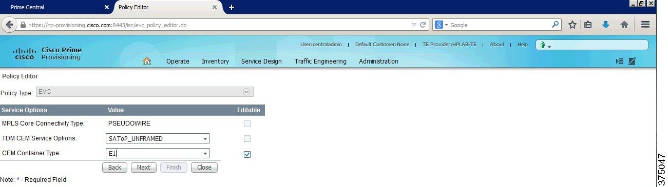
Step 3 Select service options, as shown in Figure 6-34.
Note The Alstom relays use SAToP over E1.
Figure 6-34 Cisco Prime Provisioning New Policy—2
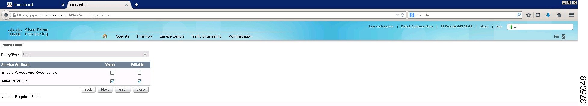
Step 4 Select service attributes, as shown in Figure 6-35.
Figure 6-35 Cisco Prime Provisioning New Policy—3
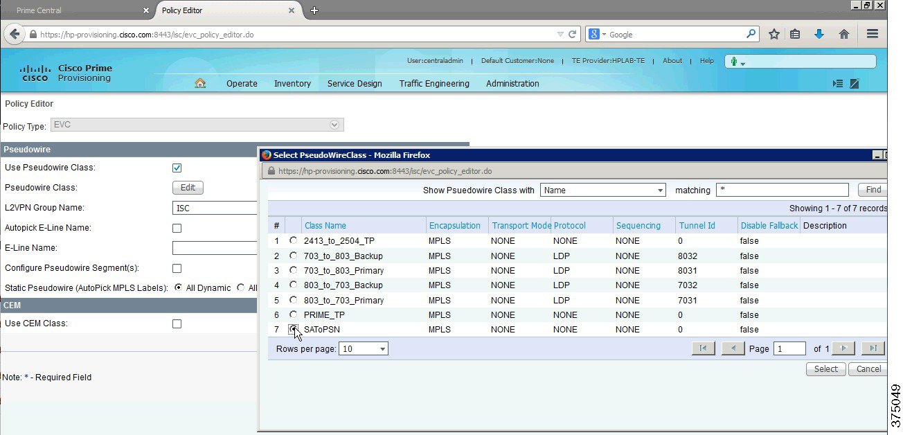
Step 5 Fill in pseudowire and CEM details and select a pseudowire class, as shown in Figure 6-36.
Figure 6-36 Cisco Prime Provisioning New Policy—4
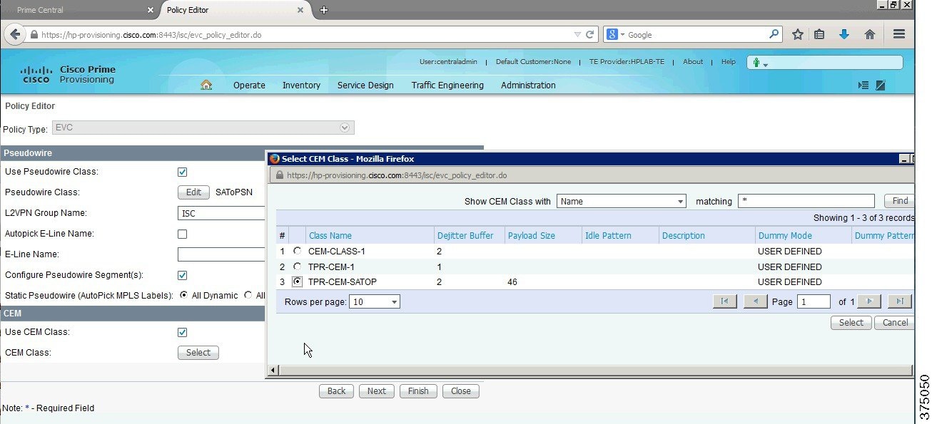
Step 6 Enable and select a CEM class, as shown in Figure 6-37.
Figure 6-37 Cisco Prime Provisioning New Policy—5
Commissioning the Service on a New E1 CEM Interface
To create an E1 interface using correct timeslots and an EVC Service that applies the CEM Class and Pseudowire Class, complete the following steps:
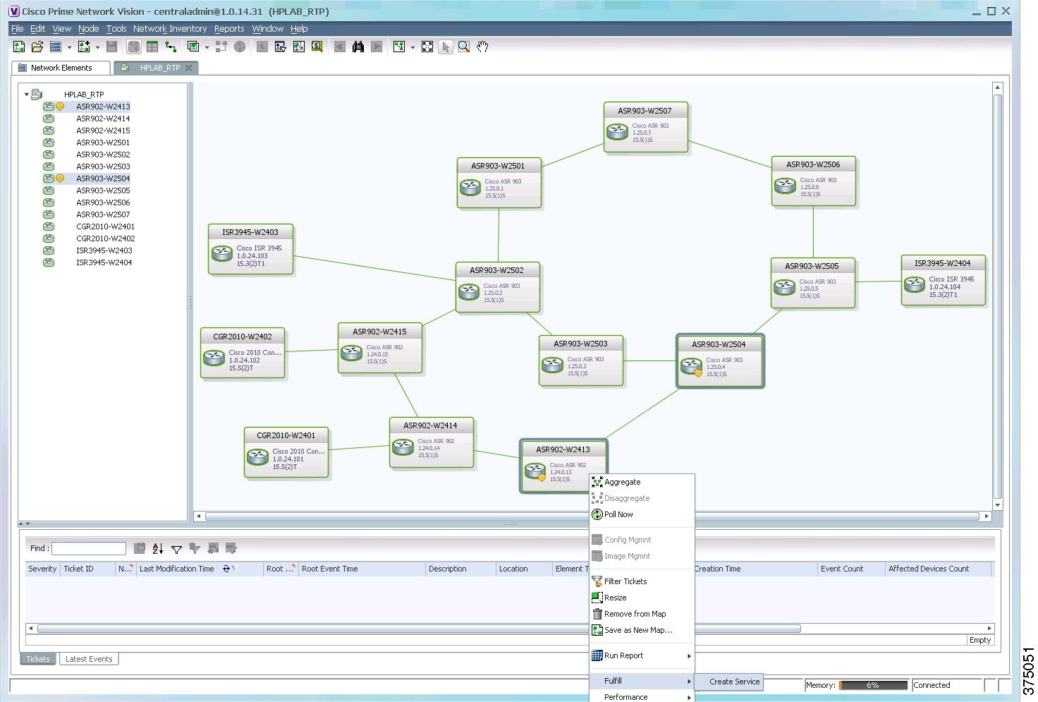
Step 1 Launch Topology from Prime Vision. Select the devices for which to create a service, as shown in Figure 6-38.
Figure 6-38 Cisco Prime Network Select Devices for Service Fulfillment
Step 2 Once Cisco Prime Provisioning is launched, select the Teleprotection_TP_SAToP (EVC) service request. Select CEM Class and interfaces, as shown in Figure 6-39.
Figure 6-39 Cisco Prime Provisioning New Teleprotection_TP_SAToP Service Request—1
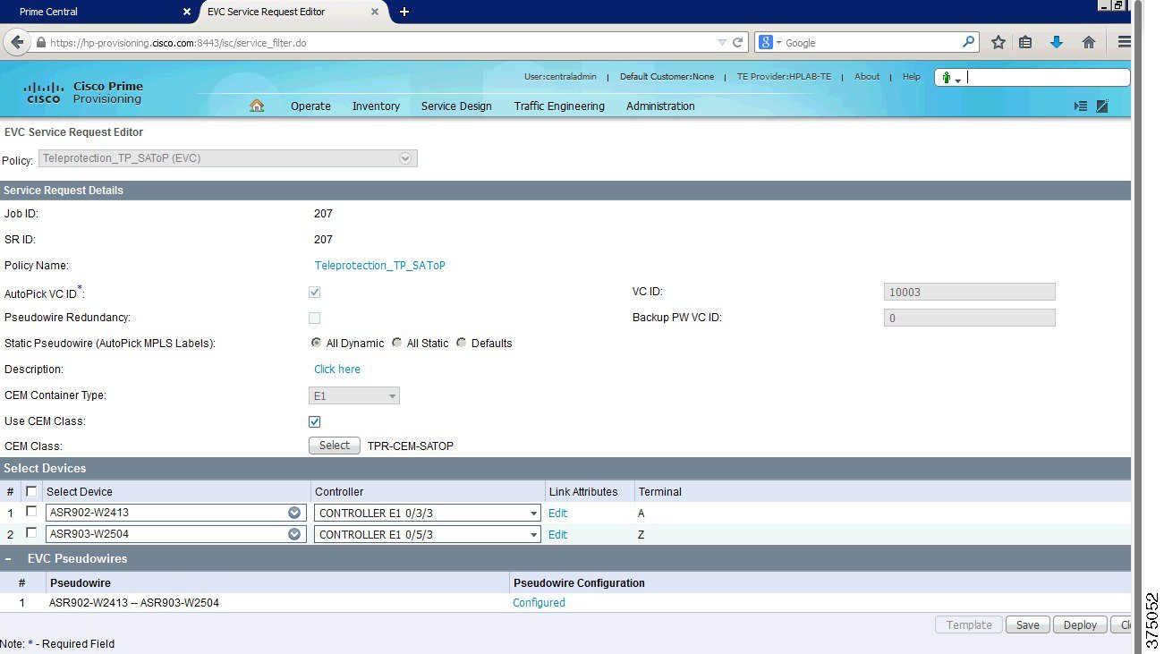
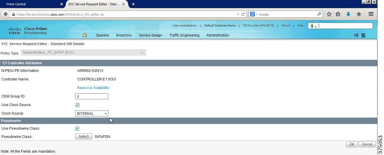
Step 3 Edit the Link Attributes. Enter a CEM group ID, clock source internal, timeslots 1, and select pseudowire class, as shown in Figure 6-40.
Figure 6-40 Cisco Prime Provisioning New Teleprotection_TP_SAToP Service Request—2
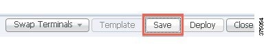
Step 4 Save the service request, as shown in Figure 6-41.
Figure 6-41 Cisco Prime Provisioning New Teleprotection_TP_SAToP Service Request—3
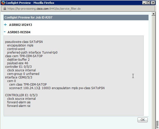
Step 5 Preview the configurations to be applied, as shown in Figure 6-42.
Figure 6-42 Cisco Prime Provisioning New Teleprotection_TP_SAToP Service Request—4
 Feedback