-
null
VMS Technology
As VMS evolves, new technology or concepts will be integrated into the solution to meet the architecture goals set forth for the release. VMS architecture goals included solution simplification, solution modularization, solution extendibility, and solution hardening, technology added in the VMS 2.0 release start to address these areas.
Service Interface
The Customer Facing Service (CFS) role is VMS Solution customer experience, it is the responsibility of the Service Interface to capture the service intent of the customer and then form the service request to the Network Service Orchestrator (NSO). The Service Interface is composed to two subsystems, the Front-End and the Back-End. The Front-End is the Web portal that supports several roles, admin, operator, and customer. Based on a Username/Password combination, the Service Interface will determine the role of the user based on the log on authentication process. With a successful authentication, the user is directed to the Web based on the pre-defined role of the username. The Back-End is the composition of micro-services that together communicate with various components in the VMS Solution. From the customer perspective, the Back-End is responsible for processing their service intent, based on the interaction with the customer Web interface or self-service user portal, and creating a parameterized service request to send to the VMS Platform NSO.
Figure 6-1 shows a modular view of the Service Interface, the Front-End consists of several portal interfaces, that based on a user role, provides the following operations:
The VMS Services that are available through the portals are dependent on the Service Packages made available by the Service Provider; currently VMS 2.0 provides the Cloud VPN Service Package. Access to various interface portals is based on the role of the user, determined during the login process; all interface access is secured by a password. The VMS Service Interface utilizes an OpenAM ID system to determine customer identity; the user login information is available to the Front-End and Back-End modules.
The Service Interface Back-End communicates with the Front-End through a REST API Gateway. The interface portals of the Front-End rely on Back-End micro-services to process user data entered in the various interface portal screens. Dependent on the type of interface portal and data entered, the information will be sent to/from the Back-End API and delivered to/sent from the micro-service responsible for processing the incoming data. The Back-End micro-services are responsible for multiple functions listed below; individual micro-services will communicate with VMS modules or other OSS modules to fulfill their functions.
–![]() Identity Management (Authentication & Federation)
Identity Management (Authentication & Federation)
–![]() Manage (Service Provisioning and Life-Cycle)
Manage (Service Provisioning and Life-Cycle)
–![]() Monitor (Service Status & Metrics)
Monitor (Service Status & Metrics)
–![]() Orchestration (NSO RFS Integrations)
Orchestration (NSO RFS Integrations)
–![]() Notification (Email Templates)
Notification (Email Templates)
–![]() Scalable, swappable and extensible (DevOps Enablement)
Scalable, swappable and extensible (DevOps Enablement)
–![]() Each service can be deployed independently of other services - easier to deploy new versions of services frequently
Each service can be deployed independently of other services - easier to deploy new versions of services frequently
–![]() Each micro service is relatively small (Easier for a developer to understand)
Each micro service is relatively small (Easier for a developer to understand)
–![]() Improved fault isolation. For example, if there is a memory leak in one service then only that service will be affected
Improved fault isolation. For example, if there is a memory leak in one service then only that service will be affected
–![]() Each service can be developed and deployed independently
Each service can be developed and deployed independently
–![]() Eliminates any long-term commitment to a technology stack
Eliminates any long-term commitment to a technology stack
–![]() Use our out-of-box UI or build your own
Use our out-of-box UI or build your own
Figure 6-1 Service Interface Reference Architecture
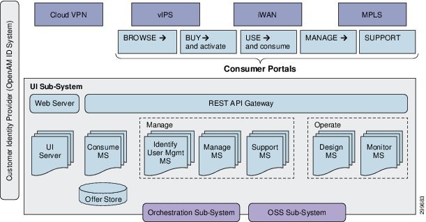
VMS 2.0 introduces the Service Interface and serves as the Customer Facing Service layer in the architecture. Designed as two separate modules, the Service Interface’s Front-End and Back-End both play important roles in simplifying the provisioning of services.
As part of solution simplification, the Front-End is designed as an all in one Web based solution GUI. Based on the user login type, the user will be presented with one of three service interfaces: administer, operator, or user. The Service Interface, based on user role, will allow the Service Provider administrator to provision tenant space for end-users, while the Service Provider operator can view the status of all services running, and lastly the user role is for the Service Provider end-customer to order the service based on their requirements.
The Service Interface also contains an independent Back-End module that is responsible for forming a user service definition or intent into a well-defined request to present to the VMS Platform for service provisioning. The Back-End is designed with a REST interface, allowing the Service Provider the choice of Front-Ends, the VMS Service Interface or another OSS front-end. The logic behind the inclusion of a Service Interface Back-End is to ensure a well-formed service request message to the VMS Solution.
Service Interface—Front-End, The VMS Customer Experience
When accessing the Service Interface Web interfaces, the user will be presented with a login screen as shown in Figure 6-2, based on the user login, they will be present with interface portal for their defined role.
Figure 6-2 VMS Service Interface: Login Screen

When logging in as the administrator, the user is presented with the screen in Figure 6-3. As the administrator, VMS service management and customer/tenant domain management are managed from this service interface, the administrator is a Service Provider role.
Figure 6-3 VMS Service Interface Administrator: Welcome Screen

To create a new Tenant domain, the administrator would select Tenants, as Figure 6-4 shows the Managed Tenants screen is displayed based on this action. A Tenant is an enterprise who has contracted for VMS Managed Services from a Service Provider.
Figure 6-4 VMS Service Interface Administrator: Mange Tenant Screen

Once a system is active, the Service Provider can utilize the operator role to monitor the services, as shown in Figure 6-5. This service portal is used by the Service Provider to monitor customer (tenant) services.
Figure 6-5 VMS Service Interface: Operator Screen

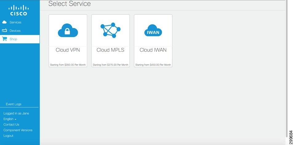
For tenant/customer accounts, the Service Provider can reduce their operational costs by providing access to the Service Interface self-service user portal, allowing customers to dynamically order and provision their service. The Service Provider has the option of ordering and provisioning services or they can optimize this operation by allowing customers the ability to manage their own Cloud VPN Service. With this option, the customer has the capability to preform the following actions on a VMS Service: create, read, update or downgrade. Figure 6-6 depicts the interface screen presented to the user, when the customer choose to ‘Shop’, a list of Service Packages is provided.

Note![]() The list of Service Packages is based on the types of services offered by the Service Provider and supported by the VMS release.
The list of Service Packages is based on the types of services offered by the Service Provider and supported by the VMS release.
Figure 6-6 VMS Service Interface: Select Service Screen
VMS 2.0 supports the Cloud VPN Service Package, future releases will expand the type of services available with the addition of new Service Packages. The VMS utilizes an agile development model; using this approach, the goal is to release new Service Packages on a frequent and regular basis. After choosing the Cloud VPN Service Package type, the customer is presented with several Cloud VPN services, along with there associated attributes, Figure 6-7 depicts this choice.
Figure 6-7 VMS Service Interface: Cloud VPN Services (Catalog of Services for Cloud VPN)

After choosing the Cloud VPN service type, the customer is presented with a series of questions; their responses are used to model their service-intent. Figure 6-8 shows the question and answer sequence used to determine a customer’s service intent, these questions include:
- How many enterprise sites
- Number of users at each site
- Anticipated employee growth
- Bandwidth requirement – 10, 50 or 100Mbps
- Number of remote/mobile users (SSL VPN users)
- Automated recovery service option
- URL filtering – Low, Medium or High
- Intrusion Prevention Service option
Figure 6-8 VMS Service Interface: “Tell us about your company” Screen

VMS 2.0 support a Zero Touch Deployment for CPE devices deployment at customer sites. In Figure 6-9, the user selects the CPE device types for each customer site. For each site defined in the previous stage, the customer will need to add a shipping address to identify the sites to ship the CPE devices. The customer may choose a different device based on locals site requirements.
Figure 6-9 VMS Service Interface: Select Equipment Screen

After all CPE devices are selected with a shipping address entered, the customer is presented with the summary of the selected CPE devices, along with their cost and shipping addresses. Figure 6-10 depicts the choice of 3 CPE devices for a service with three defined sites.
Figure 6-10 VMS Service Interface: Installation Address Screen

Finally, Figure 6-11 shows the ‘Order Summary’ for the service the customer just built. The customer will be asked to review the order, followed by an option to purchase. Note, through this process, the customer has defined the service intent through a series of questions and answers, the next phase will be handled by the Service Interface Back-End, the creation of the service request to the VMS Platform.
Figure 6-11 VMS Service Interface: Order Summary Screen

Cloud VPN Services—VNF Types
VMS 2.0 includes a total of 5 VNF types, which are bundled into several Service Packages, they include:
- vRouter —IPSec aggregation device and service router, deployed on CSR1000V
- vFirewall —Internet Firewall with NAT and Remote Access VPN, deployed on an ASAv
- vWeb Security —Enhance Web Filtering, deployed on an WSAv
Cloud VPN VNF Types include the following virtual functionality and resource requirements as defined in Table 6-1 .
|
|
|
|
|
|
|
|---|---|---|---|---|---|
Virtual Router (vRouter)
vRouter is functionality instantiated on a CSR1000V device hosted on a KVM hypervisor running on a VMS PoD UCS-C220 production server within an Canonical OpenStack Virtual Infrastructure.
|
|
|
|
|
|
|
|---|---|---|---|---|---|
The vRouter is responsible for IPSec connectivity to all enterprise sites, this is accomplish with a Virtual Template Interface (VTI) which uses a profile that defined within the configuration:
All site connecting to the vRouter are placed into the IVRF virtual routing forward table, isolating the site domain into a virtual private network:
The vRouter supports Site-2-Site enterprise connectivity, for traffic destined to the Internet, a default route is used to send traffic toward the vFW:
Refer to vRouter Configuration—Show Run.
Virtual Firewall (vFW)
Virtual Firewall (vfirewall) functionality is instantiated on an ASAv device hosted on a KVM hypervisor running on a VMS PoD UCS-C220 production server within an Canonical OpenStack Virtual Infrastructure.
|
|
|
|
|
|
|
The vFirewall created a DMZ between the Enterprise and Internet and serves as an aggregation point for all enterprise sites accessing the Internet. In addition, the vFW host the Remote VPN Service, which allows mobile uses to connect through a ssl-vpn session to enterprise resources. The configuration snippet below identifies both the inside and outside interface, creating a clear demarcation between the private tenant and public address spaces.
Traffic traversing these interfaces will have NAT applied, where the source address is mapped to a public address, maintaining the integrity of the inside address domain, this is often referred to as topology hiding.
For the Advanced w/Web Security Service, based on an access-list, the vFW will redirect (wccp-redirect) traffic to the virtual Web Security vNF for additional http security processing.
As a firewall, the ASAv inspect command is use to inspect an outgoing traffic stream and create temporary pinhole in the firewall allowing return traffic from destination/application to pass.
Remote/mobile user access to the enterprise is provided through a Remote VPN Service; this service is configured as a webvpn on the vFW. The endpoint is considered unmanaged and the remote/mobile user must download the Anyconnect client to access the enterprise. When the user accesses the Remote VPN service access point, based on configuration, they will be directed to download the anyconnect client for their specific endpoint type.
Refer to vFirewall Configuration—Show Run.
Virtual Web Security (vWS)
Virtual Web Security (vWS) functionality is instantiated on a WSAv device hosted on a KVM hypervisor running on a VMS PoD UCS-C220 production server within an Canonical OpenStack Virtual Infrastructure.
|
|
|
|
|
|
|
|---|---|---|---|---|---|
The virtual Web Security is part of the Cloud VPN Advanced w/Web Security service and provides enhanced web security through web URL filtering. Three configuration levels are available: base, medium and high Web filtering security level instantiated on the WSAv. The default security level is the medium, however it can be modified after the day 1 configuration.
The following XML templates for the vWS are included in the function pack, these files define the various security levels.
VMS Cloud VPN Service Scaling Per VMS PoD Type
The amount of Cloud VPN Services per VMS PoD will depend on the type of VMS PoD and type of services instantiated ( Table 6-2 ). VMS offers three PoD Models, all have the same number of control and compute/storage servers. The type of PoD deployed is defined by the number of production compute servers. These host the VNF based services used to extend the enterprise boundary into the Service Provider VMS Cloud.
|
|
|
|
|
|---|---|---|---|
Based on the type of Cloud VPN Service instantiated, the amount of resources required will differ significantly. Table 6-3 identifies the number of vCPU(s) required for each service type; this number has a significant effect on the total number of deployable services on a VMS PoD. As the last column indicates, the Total Required vCPU column, the cost of the Intrusion Prevention Service option on the Advanced and Advance w/Web Security services more than doubles the vCPU required for the standard deployment of these services.
|
|
|
|
|
Required vCPU |
|---|---|---|---|---|
VMS 2.0 is the initial General Availability release of the virtual Managed Service Solution, at this point there is no data, based on a customer deployment, of an actual Cloud VPN Service type ratio model. As a stake in the ground, the following calculation of the total number of Cloud VPN Services deployable based on the type VMS PoD, is based on provisioning a single service type. Figure 6-12 shows the calculated number of services based on service type deployed on a specific VMS PoD type.
Figure 6-12 Total Cloud VPN Services based on VMS PoD and Service Types
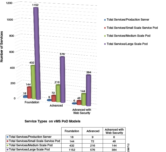
The Foundation service with a single VNF allows a Service Provider to maximize the number of enterprise being hosted on their VMS PoD. Moving forward, as actually service deployment ratios model emerge, VMS will recommend a service ratio to maximize VMS PoD utilization.
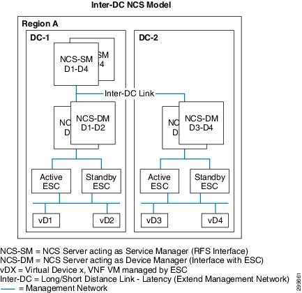
NSO Clustering
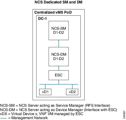
For Service Providers requiring a distributed deployment across multiple data centers, the VMS NSO supports a clustering model. The NSO clustering model identifies two defined roles for the NSO, a Service Manager (SM) and a Device Manager (DM); these role types are deployed using separate virtual devices. A single centrally located NSO SM supports multiple DM(s), where DM(s) are deployed in each data center. With the clustering model, a single NSO SM interfaces with the Service Interface Back-End to process the end-to-end service request. When a device specific configuration is identified from the processing of the service request, the NSO SM communicates with the NSO DM responsible for the configuring the actual virtual device in the appropriate data center. Using this capability VMS can supported a distributed environment, where a Service Provider can opt to deploy several VMS PoD to increase scale and lower service access latency.
The NCS-SM processes incoming service requests through the NSO RFS API(s), the processing of service requests are based on the service models made available through VMS Function Packs. As the service request is parsed, based on the logic of the Fastmap code associated with a specific service model, the NCS-SM will forward device specific requests to the NSO DM responsible for the provisioning and management of the device. Each NCS-DM and its associated VMS PoD will have a dedicated Virtual Infrastructure Manager; in VMS 2.0, the NCS-DM orchestrates the VNF devices through a dedicated ESC.
For simplicity, Figure 6-13 shows a centralized NCS being deployed in its two roles, as a Service Manager and as a Device Manager. With this deployment, where there is only one data center, the Service Provider is positioned to extend their Cloud VPN footprint by adding an additional VMS PoD in the future.
Figure 6-13 Centralized VMS Deployment
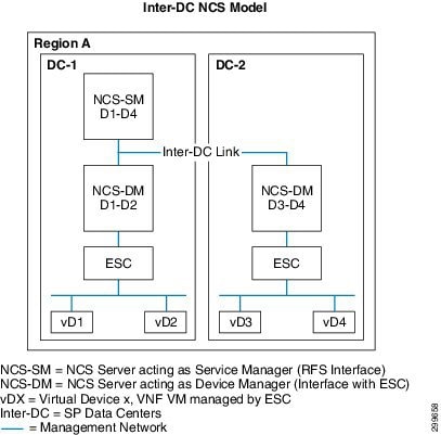
As previously noted, the Cloud VPN footprint can be extended by simply adding a new VMS PoD with a dedicated NCS-DM and ESC, thus creating a distributed VMS deployment model. Figure 6-14 shows a single NCS Service Manager, in DC-1, provisioning VMS services across virtual devices 1-4, with virtual devices 1-2 under the control of the NCS-DM in DC-1 and virtual devices 3-4 under the control of the NCS-DM in DC-2. Although VMS clustering supports distributed NCS Device Managers, VMS does not support a VMS Cloud VPN service distributed across multiple servers or data centers. A Cloud VPN service request is always provisioned on a single VMS PoD Productions server.
Figure 6-14 Distributed VMS Deployment with NSO Clustering
Redundancy
VMS is in the early stages of an evolving redundancy model which in future releases will be the foundation for a high-availability model capable of meeting a multiple-nine service level agreement. VMS 2.0 offers service path redundancy and rudimentary redundancy capabilities on a per component basis. The following sections reviews the current state of redundancy in the following areas:
- VMS Service Path Redundancy
- VMS Platform—ESC Redundancy
- VMS Platform—NSO Redundancy
- VMS VIM Redundancy
Cloud VPN Service Path Redundancy
VMS service path redundancy is addressed through the deployment of secondary data path which utilizes a separate VMS Data Center PoD. Figure 6-15shows the Advanced Service with the redundant data paths, note the following details:
- Dual Links from the Site CPE device
- Two Cloud VPN Advanced Service provisioned in separate Data Centers
- Inter vRouter Link between the Two Cloud VPN Advance Services
- Routing Updates
Figure 6-15 Service Chain Redundancy
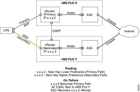
When redundancy is selected as an option, during the Service Interface self-service user portal Q&A, a requirement for a second cloud VPN service will be included as part of the service request, this additional service path will be provisioned on a separate VMS PoD data center. With redundancy, the local site CPE device will have an additional IPSec tunnel, for a total of two access tunnels, each tunnel connects to a separate Cloud VPN service; both of these connections are technically active. There is no concept of secondary Cloud VPN service, one service has a lower route preference and therefore loss costly from a routing perspective, by default the lower cost route is the path to the primary Cloud VPN service. If the lower cost vRouter fall silent, meaning the CPE loses the “active” route, the path re-routes to the higher cost service path.
ESC Redundancy
ESC redundancy uses a Master-Slave model, in this scenario, one ESC, acting as the Master, is the active device for VNF management while a second ESC, acting as a Slave, is the standby device. The two ESC devices utilize a keep-alive mechanism between the two devices, if the Master falls silent, the Slave will promote itself to Master. When failing over, the state of the PostgreSQL database must reflect the current state of all VNFs in the VMS PoD, the Master and Slave ESC must have the same view of the database when a failover occurs. ESC has two models, an external storage approach using the OpenStack Cinder service and a local storage approach using Distributed Replication Block Device (DRBD).
Externally, a virtual IP address (VIP) provides a single address for the ESC model, a lightweight ExaBGP process advertises routing from the Master ESC.
Figure 6-16 shows the ESC redundancy model utilizing Cinder as an external storage device. The critical redundancy components are highlighted:
- VIP —Virtual IP Address based on VRRP (virtual Router Redundancy Protocol)
- Keep-alive Daemon —Transmit and Monitor Keep-alive(s) between Master/Slave ESC devices
- PostgreSQL —Common Database
- Cinder —OpenStack’s Block Storage as a Service
- External Storage —UCS Storage Server
In a failure scenario, the Master ESC device goes silent, as determined by the Slave ESC device’s Keep-alive daemon/process. The Slave ECS device transitions to the active role becoming the new Master ESC. The new Master ESC advertises itself as the active route, resulting in all VNF Manager traffic being routed to it. The new Master ESC will than transition the external Cinder block device from the old Master ESC to itself. The new Master ESC’s PostgreSQL now has access to the database that was previously used by the former PostgreSQL on the old Master ESC.
Figure 6-16 External Block Storage accessed by OpenStack Cinder
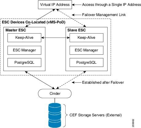
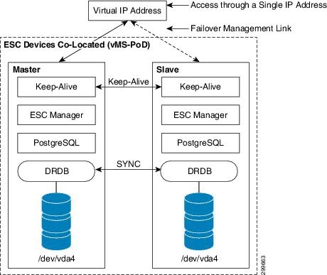
Figure 6-17 shows the ESC redundancy model utilizing DRBD to replicate the PostgreSQL database from the Master device the Slave Device. The failure-over mechanism for this model is the same as the former; the differing critical redundancy components are highlighted:
The primary difference with this model versus the former is location of the PostgreSQL data, each ESC device maintains a local database. To maintain consistency across a fail-over, DRBD is used to sync data continuously from the Master ESC device to the Slave ESC device.
Figure 6-17 Local Storage Data Replication with DRDB
NSO Redundancy
Failure of the NSO device would result in the loss Cloud VPN state which is stored in the CDB. The NSO is responsible for initiating Create, Read, Update and Delete operations based on the service request from the user’s service intent. The CDB represents the current state of the system from an orchestration perspective, including occupancy, resources pools, and the state of all services deployed through NSO. Loss of this database would leave the system ‘head-less’ with no way service aware manner to interact with southbound modules or devices, i.e. ESC and VNF devices. In addition, from an end-user perspective the system orchestration would be dead, with no NSO to interact with the Service Interface.
NSO redundancy is based on the presence of two NSO devices, where one device maintains the master CDB, the second, the subordinate CDB. All RFS API service request are processed by the master NSO. The master NSO maintain synchronization with the subordinate NSO. When the master NSO fails, the subordinate NSO becomes the new master. The master and subordinate use vRRP or BGP to maintain a keep alive state, when the subordinate loses communication with the master it triggers a switchover. The NSO can be in three states:
- Master —Active Device, NSO is syncing to NSO Slave
- Subordinate —Standby Device, NSO device has synced with NSO Master
- None —No Active Redundancy State
Figure 6-18 shows the NSO when in each of these states.
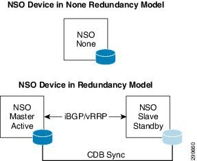
Figure 6-19 shows how the redundant NSO devices are deployed in a redundant VMS cluster deployment. Both NSO roles, Service Manager and Device Manager are redundant, the redundant NSO-DM devices communicate directly with two ESC devices in redundant mode.
Figure 6-19 NSO Redundancy in VMS Cluster Deployment
VMS Virtual Infrastructure Manager—High Availability
VMS assumes the installation of Canonical OpenStack as the Virtual Infrastructure Manager (VIM). The Redundancy model for OpenStack is outside the scope of the VMS Platform architecture, however the VMS Solution assumes OpenStack controllers are redundant and operating within a High Available framework.
From a high level, to achieve High Availability of the OpenStack controllers, a clustering model is utilized that requires a minimum of three servers acting as controllers. Clustering is achieved through two OpenStack service packages: Pacemaker and Corosync, both packages are installed on all controller servers. The Pacemaker package includes a cluster resource manager capable of providing high availability and load balancing services to Linux applications and services. To achieve this Pacemaker relies on a message system to determine state of each service on a clustered node. This message system is provided by Corosync which uses UDP as transport protocol between the servers forming the cluster. Both multicast and unicast modes of message communication are supported but for this solution the unicast mode is used.
The Corosync package loads the Corosync Cluster Engine, providing group communication services. The Corosync API provides the following capabilities:
- A closed process group communication model with virtual synchrony guarantees for creating replicated state machines.
- A simple availability manager that restarts the application process when it has failed.
- A configuration and statistics in-memory database that provide the ability to set, retrieve, and receive change notifications of information.
- A quorum system that notifies applications when quorum is achieved or lost.
 Feedback