Installing Cisco Cloud Network Automation Provisioner for the Microsoft Cloud Platform, Release 2.1
Bias-Free Language
The documentation set for this product strives to use bias-free language. For the purposes of this documentation set, bias-free is defined as language that does not imply discrimination based on age, disability, gender, racial identity, ethnic identity, sexual orientation, socioeconomic status, and intersectionality. Exceptions may be present in the documentation due to language that is hardcoded in the user interfaces of the product software, language used based on RFP documentation, or language that is used by a referenced third-party product. Learn more about how Cisco is using Inclusive Language.
- Updated:
- August 10, 2016
Chapter: Installing Cisco Cloud Network Automation Provisioner
- Introduction
- Prerequisites for Installing Cisco Cloud Network Automation Provisioner
- Setting Up and Configuring Network Resources and Services
- Installing and Configuring Microsoft Windows Azure Pack
- Installing and Configuring Cisco Application Centric Infrastructure Plugins for Microsoft System Center Virtual Machine Manager and Hyper-V
- Setting Up the Environment and Target Virtual Machines
- Installing and Configuring Microsoft Service Bus 1.1
- Adding the VMM Service into a Local Trust with the Cisco CNAP Admin API Server
- Overview of Cisco Cloud Network Automation Provisioner Installation
- Installing the Cisco Cloud Network Automation Provisioner
Installing Cisco Cloud Network Automation Provisioner
Introduction
The Cisco Cloud Architecture for Microsoft Cloud Platform (CCA for MCP) solution delivers IaaS, PaaS, and SaaS with integrated management software. The data center infrastructure is built with Cisco Application Centric Infrastructure (ACI) for the Data Center Fabric and Cisco UCS-based compute, Cisco Adaptive Security Appliance (ASA) firewall for security, and Cisco Aggregation Services Routers (Cisco ASR 9000 and Cisco ASR1000) data center edge routers. Additionally, Cisco virtualized network functions such as Cisco Cloud Services Router 1000V (CSR 1000V) are used to implement tenant services.
Microsoft Hyper-V Hypervisor is used as the virtualizing layer for compute to run tenant workloads. The Management Stack is based on Microsoft Windows Azure Pack (WAP), which allows service providers to create plans and tenant administrators to subscribe to those plans.
CCA for MCP enables service providers to host and offer sophisticated tenant network containers over a Cisco cloud infrastructure, enabling tenants to deploy multi-tier applications in the cloud. The provisioning of such containers is enabled by the use of the Cisco Advance Data Center Network Resource Provider in the Microsoft Windows Azure Pack Portals. Cisco Cloud Network Automation Provisioner (CNAP) software includes the Cisco Advance Data Center Resource Provider component, which exposes the Cisco infrastructure resources to the:
- Service Provider Cloud Admin to publish plans that offer complex network containers
- Tenant to use the subscriptions to instantiate the network containers and, using the VMClouds Resource Provider, deploy tenant workloads and attach to tenant Virtual networks
A Microsoft WAP administrator can use Cisco CNAP for MCP Admin Portal to configure, manage, and administer Cisco Data Center Network resources. Cisco CNAP provides the capability to create tenant containers with sophisticated network services such as tenant edge routing, multiple security zones, firewalling, NAT, MPLS VPN access, and Server Load Balancing. The administrator uses the portal to define and set up the available plans that will be visible in the Tenant Portal and that can be consumed by tenants. Tenants consume resources by using the Tenant Portal to subscribe to an available plan. This allows service providers to offer differentiated plans that provide more value to tenants and generate more revenue for service providers, with the convenience of automation to deploy sophisticated containers for tenants.
For more information, see: http://www.cisco.com/go/cloud.
Prerequisites for Installing Cisco Cloud Network Automation Provisioner

Note![]() Cisco’s commitment to security requires that the target system(s) on which the Cisco CNAP Software is installed must be up to date with all known security patches for the Microsoft Window Server Operating System, Microsoft.NET Framework, Microsoft ASP.NET, Microsoft SQL Server, and Windows Azure Pack.
Cisco’s commitment to security requires that the target system(s) on which the Cisco CNAP Software is installed must be up to date with all known security patches for the Microsoft Window Server Operating System, Microsoft.NET Framework, Microsoft ASP.NET, Microsoft SQL Server, and Windows Azure Pack.
Administrators can consider using the Microsoft Baseline Security Analyzer (MBSA) scan tool to identify common security misconfigurations and missing security updates on system endpoints:
https://technet.microsoft.com/en-us/security/cc184924.aspx
Before you install Cisco CNAP, you must :
- Set up and configure network resources and services.
- Install and configure Microsoft Windows Azure Pack.
- Install and configure Cisco Application Centric Infrastructure plugins for Microsoft System Center Virtual Machine Manager and Hyper-V.
- Set up the environment and target virtual machines.
- Install and configure Microsoft Service Bus 1.1.
- Add the VMM Service into a Local Trust with the Cisco CNAP Admin API server.

Setting Up and Configuring Network Resources and Services
Before you install Cisco CNAP, you should:
- Build the data center infrastructure—Refer to the Cisco Cloud Architecture for the Microsoft Cloud Platform: Infrastructure Foundation Guide, Release 1.0 for detailed information on building data centers using physical components to implement compute, storage, and data center networking to create a pool of resources that are then used to offer services to tenants.
- Configure specific services—The services that are supported by the Cisco Cloud Architecture for the Microsoft Cloud Platform architecture include Infrastructure as a Service (IaaS) with Zinc Container, Database as a Service (DBaaS), Disaster Recovery as a Service (DRaaS), etc. You must set up these services before you use Cisco CNAP to configure access to them. See Table 2-1 in the Preface for:
–![]() Specific configuration requirements for these services in the various configuration documents.
Specific configuration requirements for these services in the various configuration documents.
–![]() More information on using Cisco CNAP to configure access to these services, see Cisco Cloud Network Automation Provisioner for the Microsoft Cloud Platform—Admin Portal Guide, Release 2.1.
More information on using Cisco CNAP to configure access to these services, see Cisco Cloud Network Automation Provisioner for the Microsoft Cloud Platform—Admin Portal Guide, Release 2.1.
Installing and Configuring Microsoft Windows Azure Pack
Microsoft WAP must be installed before installing Cisco CNAP. This document does not discuss the installation of Microsoft WAP. The basic prerequisites for Microsoft WAP are:
For comprehensive information on Microsoft WAP prerequisites and installation, see:
- Windows Azure Pack for Windows Server
https://technet.microsoft.com/en-us/library/dn296435.aspx
- Windows Azure Pack installation checklist
https://technet.microsoft.com/en-us/library/dn469338.aspx - Windows Azure Pack system requirements overview
https://technet.microsoft.com/en-us/library/dn296442.aspx
Useful Microsoft Windows Azure Pack References
The following sources may provide useful information about Microsoft WAP:
- WAP Wiki—Source for general information on Microsoft WAP
http://social.technet.microsoft.com/wiki/contents/articles/20689.the-azure-pack-wiki-wapack.aspx - Building Clouds Blog—Maintained by the Windows Server & System Center Customer Advisory Team.
–![]() Overview of WAP on the blog
Overview of WAP on the blog
http://blogs.technet.com/b/privatecloud/archive/2013/12/20/building-clouds-windows-azure-pack-blog-post-overview.aspx
–![]() Installing and Configuring Series
Installing and Configuring Series
http://blogs.technet.com/b/privatecloud/archive/2013/12/06/windows-azure-pack-installing-amp-configuring-series.aspx
–![]() Troubleshooting Installation and Configuration of WAP—Introduction
Troubleshooting Installation and Configuration of WAP—Introduction
http://blogs.technet.com/b/privatecloud/archive/2013/11/05/troubleshooting-configuration-of-windows-azure-pack.aspx
- PLA—Important as the IaaS Fabric and Fabric Management PLAs are the root source for SPRA and Fast Track.
–![]() Overview
Overview
http://blogs.technet.com/b/privatecloud/archive/2014/04/28/iaas-product-line-architecture-available-for-download.aspx
–![]() Deployment Guide
Deployment Guide
https://gallery.technet.microsoft.com/Infrastructure-as-a-ecf1cc0b
–![]() Cisco Fast Track—Provides extensive step-by-step instructions
Cisco Fast Track—Provides extensive step-by-step instructions
http://www.cisco.com/c/en/us/solutions/data-center-virtualization/microsoft-applications-on-cisco-ucs/index.html
Installing and Configuring Cisco Application Centric Infrastructure Plugins for Microsoft System Center Virtual Machine Manager and Hyper-V
To enable the Microsoft System Center Virtual Machine Manager (SCVMM) to communicate with the Cisco Application Policy Infrastructure Controller (APIC), every host in your Hyper-V cluster must run the Hyper-V plugin and you also must install the SCVMM plugin. Do not use the Cisco Application Centric Infrastructure (ACI) Resource Provider for WAP.
Cisco ACI is a next-generation data center fabric infrastructure designed using an application policy model, allowing the entire data center infrastructure to better align with application delivery requirements and business policies of an organization. Integrating with Microsoft Windows-based application servers running the Microsoft Hyper-V hypervisor, Cisco ACI provides tight integration between physical and virtual application environments.
Cisco extends the Cisco ACI policy framework to the Microsoft Windows Server Hyper-V with Microsoft System Center and Microsoft Azure Pack.
Integrating Cisco Application Centric Infrastructure with Microsoft Hyper-V
The Cisco APIC integrates with a SCVMM instance to transparently extend the Cisco ACI policy framework to Microsoft Hyper-V workloads. The Cisco APIC uses Application Network Profiles (ANPs) to represent the Cisco ACI policy. The ANPs model the logical representation of all components of the application and its interdependencies on the Cisco ACI fabric. After these ANPs are defined in the Cisco APIC, the integration between Microsoft SCVMM and the Cisco APIC helps ensure that these network policies can be applied to Microsoft Hyper-V workloads. The network policies and logical topologies (VLANs, subnets, etc.) that have traditionally-dictated application designs are now applied based on the ANP through the Microsoft APIC.
The Cisco ACI service plugin helps enable management of network infrastructure through the APIC REST API. The Cisco APIC integrates with Microsoft SCVMM to simplify workload connectivity. To connect Windows Server Hyper-V workloads to the Cisco ACI fabric, the virtualization administrator simply needs to associate the virtual machines with the virtual machine networks created by the Cisco APIC that appear under the logical switch in Hyper-V.
The following summarizes the steps involved:
- Install the APIC SCVMM Agent on SCVMM.
- Configure APIC IP Settings with APIC credentials on the SCVMM Agent.
- Generate the APIC Hyper-V Agent OpFlex certificate.
- Add the OpFlex certificate policy to APIC.
- Install the APIC Hyper-V Agent on each Hyper-V server.
- Verify the APIC SCVMM Agent installation on SCVMM.
- Verify the APIC Hyper-V Agent installation on each Hyper-V server.
- Create SCVMM Domain Profiles.
- Verify the SCVMM VMM Domain and SCVMM VMM.
- Deploy the logical switch to the host on SCVMM.
- Cisco Application Centric Infrastructure and Microsoft SCVMM and Azure Pack
http://www.cisco.com/c/en/us/solutions/collateral/data-center-virtualization/application-centric-infrastructure/white-paper-c11-732080.html - Cisco ACI with Microsoft SCVMM
http://www.cisco.com/c/en/us/td/docs/switches/datacenter/aci/apic/sw/1-x/virtualization/b_ACI_Virtualization_Guide/cisco____aci___with_microsoft_scvmm.html - Cisco Cloud Architecture for the Microsoft Cloud Platform: Infrastructure Foundation Guide, Release 1.0
http://www.cisco.com/c/en/us/td/docs/solutions/Service_Provider/CCAMCP/1-0/Foundation/CCAMCP1_Foundation.html
Setting Up the Environment and Target Virtual Machines
For information on setting up the environment for Microsoft WAP including specific guidelines on allocating virtual machines (VMs), refer to:
–![]() SPRA Foundation—Converged Infrastructure
SPRA Foundation—Converged Infrastructure
http://download.microsoft.com/download/9/7/B/97BC02C7-3E93-4DBE-BE31-CA7E6C80B05E/SPRA v2 1 - MT - Foundation - Converged Infrastructure.docx
–![]() Service Provider Reference Architecture—Desktop Hosting Using RDSH
Service Provider Reference Architecture—Desktop Hosting Using RDSH
http://download.microsoft.com/download/A/3/0/A30480C9-86D3-4535-96D8-2BEEB1DA9E1D/Service Provider Reference Architecture - Desktop Hosting using RDSH.docx
–![]() Service Provider Reference Architecture—Database Hosting Using SQL 2014
Service Provider Reference Architecture—Database Hosting Using SQL 2014
http://download.microsoft.com/download/0/8/A/08AC4D77-C66B-4749-89AD-6AC74E79B59B/Service Provider Reference Architecture - Database Hosting using SQL Server 2014.docx
- FlexPod Datacenter with Microsoft Private Cloud Fast Track 4.0 and Cisco Nexus 9000 Series Switches Design Guide
http://www.cisco.com/c/en/us/td/docs/unified_computing/ucs/UCS_CVDs/flexpod_mspc40_cmode_n9k_design.html - FlexPod Datacenter with Microsoft Private Cloud Fast Track 4.0 and Cisco Nexus 9000 Series Switches Deployment Guide
https://www.cisco.com/c/dam/en/us/td/docs/unified_computing/ucs/UCS_CVDs/flexpod_mspc40_cmode_n9k.pdf
Note![]() Cisco CNAP software is installed on the Admin Portal server, Tenant Portal server, and CNAP Backend server. CNAP Backend can be installed on the Admin API server.
Cisco CNAP software is installed on the Admin Portal server, Tenant Portal server, and CNAP Backend server. CNAP Backend can be installed on the Admin API server.
Installing and Configuring Microsoft Service Bus 1.1
During or after WAP installation, you must install and configure Microsoft Service Bus 1.1, which is not installed during a default WAP installation.
Note![]() Install the Service Bus 1.1 for.NET Framework 4.6 patch.
Install the Service Bus 1.1 for.NET Framework 4.6 patch.
Note![]() Microsoft Service Bus 1.1 should be installed on the Admin API server.
Microsoft Service Bus 1.1 should be installed on the Admin API server.
The Microsoft Service Bus 1.1 can be downloaded using the Microsoft Web Platform Installer and can be found in the same location as all the other WAP components.
Step 1![]() Run the Service Bus Configurator.
Run the Service Bus Configurator.
Figure 1-1 Service Bus Configuration Wizard
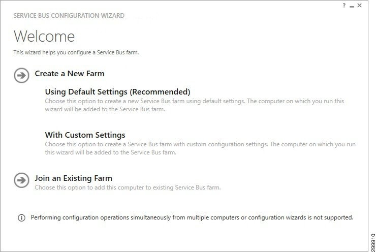
Step 2![]() Select Create New Farm −> Using Default Settings (Recommended).
Select Create New Farm −> Using Default Settings (Recommended).
Figure 1-2 New Farm Configuration—1 of 2
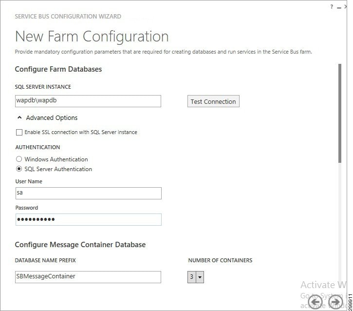
Step 3![]() In the SQL Server Instance field, enter your WAP DB Instance.
In the SQL Server Instance field, enter your WAP DB Instance.
Step 4![]() Select Advanced Options and select either Windows Authentication or SQL Server Authentication.
Select Advanced Options and select either Windows Authentication or SQL Server Authentication.
Step 5![]() Scroll down so you see the following screen.
Scroll down so you see the following screen.
Figure 1-3 New Farm Configuration—2 of 2
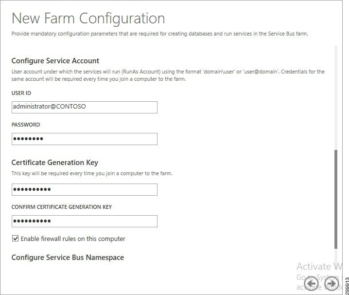
Step 6![]() Enter a Password and the Certificate Generation Key (and confirm the key).
Enter a Password and the Certificate Generation Key (and confirm the key).
Step 7![]() Click the right arrow (−>) and click Okay.
Click the right arrow (−>) and click Okay.
Cisco CNAP will configure the proper Service Bus Name Space (SBNameSpace) when it is installed.
Adding the VMM Service into a Local Trust with the Cisco CNAP Admin API Server
The VMM Service needs to be added into a local trust with the Cisco CNAP Admin API server. The VMM Service can be the SCVMM host or the VMM Cluster role if configured.
Overview of Cisco Cloud Network Automation Provisioner Installation
This section describes the installation and initial setup of the Cisco CNAP, which includes:
- Installing the Cisco Cloud Network Automation Provisioner
- Installing the Cisco NSO
- Connecting Cisco CNAP to the Cisco NSO
Post-installation verification procedures are also outlined.
Cisco Cloud Network Automation Provisioner Software Components and Prerequisites
Table 1-1 lists the Cisco CNAP components and prerequisites. This document only describes the installation of the Cisco CNAP Admin Portal, Tenant Portal, and Backend Service.
Note![]() Cisco CNAP software is installed on the Admin Portal server, Tenant Portal server, and CNAP Backend server. CNAP Backend can be installed on the Admin API server.
Cisco CNAP software is installed on the Admin Portal server, Tenant Portal server, and CNAP Backend server. CNAP Backend can be installed on the Admin API server.
Note![]() The basic prerequisites for Microsoft WAP are:
The basic prerequisites for Microsoft WAP are:
-Windows Server 2012 R2 and Patches
-Microsoft SQL Server
-System Center 2012 R2
For more information, see Installing and Configuring Microsoft Windows Azure Pack.


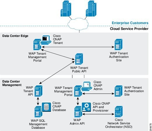
Figure 1-4 shows the interrelationships of the various components.
Figure 1-4 Cisco CNAP Components
Installing the Cisco Cloud Network Automation Provisioner
Note![]() You can use the VBScript script packaged with Cisco CNAP to install it. The advantage of using a script is that you can specify various parameters, such as run in quiet mode, produce logs that can be useful in debugging installation issues, etc. For more information, see Appendix A—Using a Script to Install Cisco Cloud Network Automation Provisioner.
You can use the VBScript script packaged with Cisco CNAP to install it. The advantage of using a script is that you can specify various parameters, such as run in quiet mode, produce logs that can be useful in debugging installation issues, etc. For more information, see Appendix A—Using a Script to Install Cisco Cloud Network Automation Provisioner.
Step 1![]() Double-click the CiscoCloudNetworkAutomationProvisioner.msi Windows installer package. This can be run with any of the normal msi switches or can be launched with the msiexec command with any of the normal switches. Logging can be enabled with any of these options.
Double-click the CiscoCloudNetworkAutomationProvisioner.msi Windows installer package. This can be run with any of the normal msi switches or can be launched with the msiexec command with any of the normal switches. Logging can be enabled with any of these options.
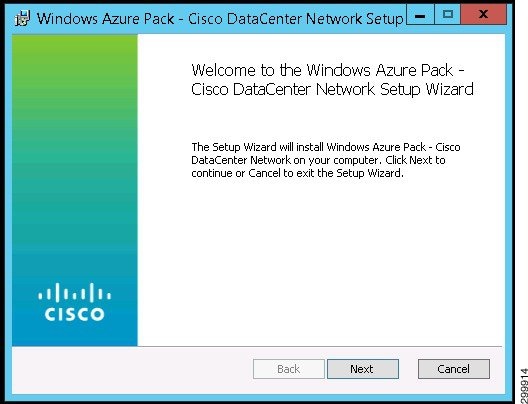
You see the Network Setup Wizard Welcome screen.
Figure 1-5 Network Setup Wizard Welcome Screen
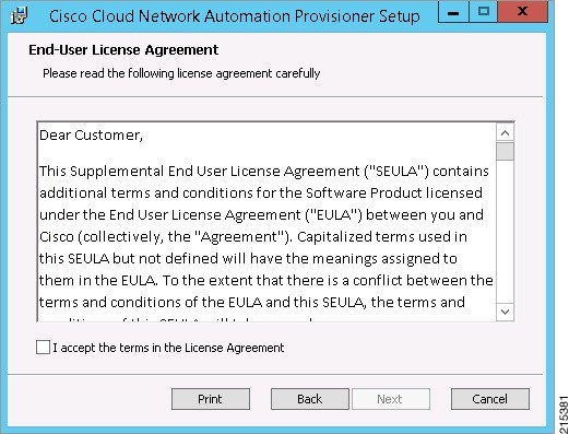
You see the End-User License Agreement screen, which has two sections you should read.
The first section is the Supplemental End User License Agreement (SEULA), the first part of which is shown in the screen below.
Figure 1-6 Supplemental End User License Agreement
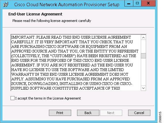
Scroll down to see the second section, the End User License Agreement (EULA), the first part of which is shown in the screen below.
Figure 1-7 End User License Agreement
Step 3![]() Click the box to accept the terms of the license agreement and click Next.
Click the box to accept the terms of the license agreement and click Next.
You see the Install Features screen.
Figure 1-8 Install Features Screen
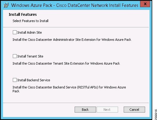
Note![]() If you initially install only one or two features rather than all three, you cannot rerun the installer to install the remaining feature(s) you did not initially install. You must first remove the initial installation. For more information, see Removing an Installation.
If you initially install only one or two features rather than all three, you cannot rerun the installer to install the remaining feature(s) you did not initially install. You must first remove the initial installation. For more information, see Removing an Installation.
Note![]() If you did a WAP express install so that all three of these features will run on the same server, then you must install all three features at the same time. If the Tenant Site will run on one server and the Admin Site and Backend Service will be installed on a separate server, then install the Tenant Site first on its server, then simultaneously install both the Admin Site and the Backend Service on their own server.
If you did a WAP express install so that all three of these features will run on the same server, then you must install all three features at the same time. If the Tenant Site will run on one server and the Admin Site and Backend Service will be installed on a separate server, then install the Tenant Site first on its server, then simultaneously install both the Admin Site and the Backend Service on their own server.
Installing the Tenant Site
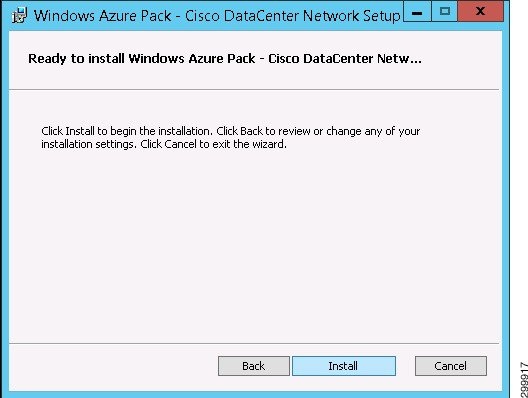
Step 1![]() If you select Install Tenant Site and click Next, you see the Ready to Install screen.
If you select Install Tenant Site and click Next, you see the Ready to Install screen.
Figure 1-9 Ready to Install Screen
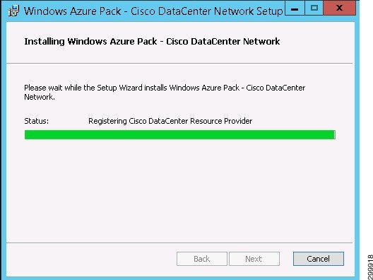
You see a screen with a status bar and messages indicating the progress of the installation.
Figure 1-10 Installation Progress Screen
When installation finishes, you see the Installation Complete screen.
Figure 1-11 Installation Complete Screen
Installing the Admin Site
Step 1![]() If you select Install Admin Site and click Next, you see the Ready to Install screen.
If you select Install Admin Site and click Next, you see the Ready to Install screen.
Figure 1-12 Ready to Install Screen
When installation finishes, you see the Installation Complete screen.
Figure 1-13 Installation Complete Screen
Installing the Backend Service
Step 1![]() If you select Install Backend Service, when you click Next you see the Prerequisite Check screen.
If you select Install Backend Service, when you click Next you see the Prerequisite Check screen.
Figure 1-14 Prerequisite Check Screen
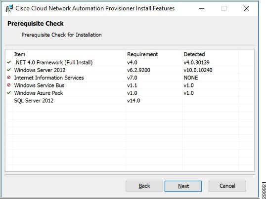
This screen displays the required and detected prerequisites. The left column indicates whether a prerequisite is met or not. Ensure all prerequisites are met before continuing.
You see the SQL Server Connection screen.
Figure 1-15 SQL Server Connection Screen
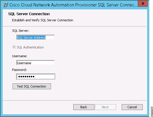
Step 3![]() Complete the following fields:
Complete the following fields:
- SQL Server: —Enter the SQL connection string in the form SQL server name \ SQL instance.
- SQL Authentication is the only option and is preselected.
- Username: —Enter your user ID for SQL authentication.
- Password: —Enter your password for SQL authentication.
Step 4![]() Click Test SQL Connection.
Click Test SQL Connection.
If the connection fails, you see the Retry Inputs. Connection Failed message.
Figure 1-16 SQL Server Connection Screen—Connection Failed Message
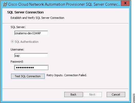
Step 5![]() Reenter the required information and click Test SQL Connection.
Reenter the required information and click Test SQL Connection.
If you have entered the correct information, you see the Connection Succeeded message.
Figure 1-17 SQL Server Connection Screen—Connection Succeeded Message
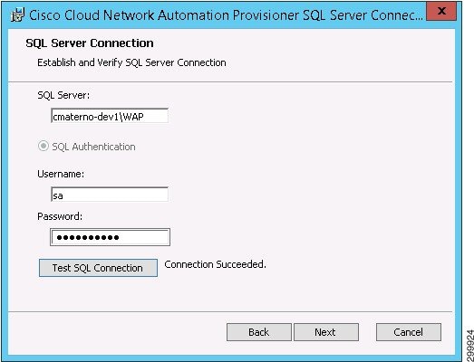
Step 6![]() When you see the Connection Succeeded message, click Next.
When you see the Connection Succeeded message, click Next.
You see the Create Service User screen.
For security reasons, you must create a service user with credentials that are different than the Microsoft WAP credentials (in addition, the username cannot have a hyphen [-] in it).
Figure 1-18 Create Service User Screen
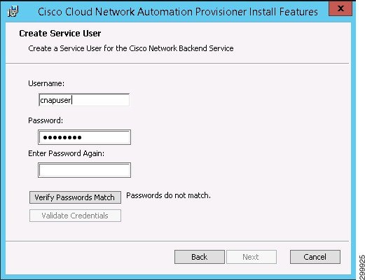
Step 7![]() Complete the following fields (the installer automatically checks to ensure the user name is unique):
Complete the following fields (the installer automatically checks to ensure the user name is unique):
- Username: —Enter a username (the username cannot have a hyphen [-] in it).
- Password: —Enter a password.
- Enter Password Again: —Reenter the password.
Step 8![]() Click Verify Passwords Match. If they do not, you see the message Passwords do not match.
Click Verify Passwords Match. If they do not, you see the message Passwords do not match.
Figure 1-19 Create Service User Screen—Passwords Do Not Match Message

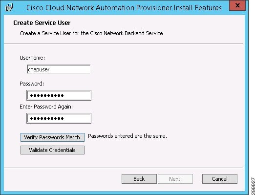
Step 9![]() Reenter the password and click Verify Passwords Match.
Reenter the password and click Verify Passwords Match.
If the passwords match, you see the message Passwords entered are the same.
Figure 1-20 Create Service User Screen—Passwords Match Message
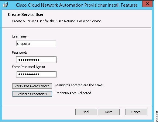
Step 10![]() Click Validate Credentials. If the credentials are correct, you see the message Credentials are validated. If the credentials are not valid, the installer will time out and y ou will see a message indicating the issue:
Click Validate Credentials. If the credentials are correct, you see the message Credentials are validated. If the credentials are not valid, the installer will time out and y ou will see a message indicating the issue:
- Password does not pass complexity check.
- User already exists at target.
- Credentials are invalid.
- Unable to verify.
If there is an error, correct the relevant item and again click Validate Credentials.
Figure 1-21 Create Service User Screen—Credentials are Validated Message
You see the Ready to Install screen.
Figure 1-22 Ready to Install Screen
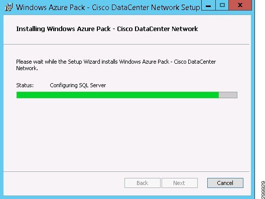
You see a screen with a status bar and messages indicating the progress of the installation.
Figure 1-23 Installation Progress Screen
When installation finishes, you see the Installation Complete screen.
Figure 1-24 Installation Complete Screen
Post-installation Set Up Procedures
After installing Cisco CNAP, either using the installer GUI or the script described in Appendix A—Using a Script to Install Cisco Cloud Network Automation Provisioner you must complete the following post-installation procedures:
Running the RegisterRP.ps1 File
You must run the RegisterRP.ps1 file via Windows PowerShell on the AdminAPI server to register the resource provider. The installer does not automatically do this.
Note![]() The Cisco CNAP Admin site runs on port 30040 for HTTP and port 30041 for HTTPS communication.
The Cisco CNAP Admin site runs on port 30040 for HTTP and port 30041 for HTTPS communication.
Configuring Global Settings for the System
Note![]() At this point, you are only required to enter the three Microsoft Service Provider Foundation (SPF) Connection settings, which let you connect to the SPF server to retrieve clouds. However we recommend that you set all global system parameters at this time.
At this point, you are only required to enter the three Microsoft Service Provider Foundation (SPF) Connection settings, which let you connect to the SPF server to retrieve clouds. However we recommend that you set all global system parameters at this time.
Before you begin configuring global settings, complete the steps in the following section as you will need this information to complete some fields
Creating the Cisco CSR 1000V Template Used by Cisco CNAP
To create the Cisco CSR 1000V template:
Step 1![]() Obtain a supported Cisco CSR 1000V.
Obtain a supported Cisco CSR 1000V.
Step 2![]() Copy the ISO image into the library ISO location of the targeted VMM and refresh the library.
Copy the ISO image into the library ISO location of the targeted VMM and refresh the library.
Step 3![]() Create a virtual machine with a blank virtual hard disk using the following configuration parameters (if not specified, the default configuration will be used):
Create a virtual machine with a blank virtual hard disk using the following configuration parameters (if not specified, the default configuration will be used):
Note![]() You can configure two (2) or four (4) CPUs. Cisco CNAP supports only one template and all Cisco CSR 1000Vs will be instantiated from the one template. See: http://www.cisco.com/c/en/us/products/collateral/routers/cloud-services-router-1000v-series/datasheet-c78-733443.html.
You can configure two (2) or four (4) CPUs. Cisco CNAP supports only one template and all Cisco CSR 1000Vs will be instantiated from the one template. See: http://www.cisco.com/c/en/us/products/collateral/routers/cloud-services-router-1000v-series/datasheet-c78-733443.html.
–![]() Virtual hard disk type is fixed and size is 8GB
Virtual hard disk type is fixed and size is 8GB
–![]() Virtual DVD driver connecting to the Cisco CSR 1000V ISO you provided
Virtual DVD driver connecting to the Cisco CSR 1000V ISO you provided
–![]() Add seven (7) additional network adapters and change all eight (8) adapters' MAC addresses to static.
Add seven (7) additional network adapters and change all eight (8) adapters' MAC addresses to static.
–![]() Enable high availability and set priority to High.
Enable high availability and set priority to High.
–![]() Change CPU priority to High.
Change CPU priority to High.
–![]() Change Memory weight to High.
Change Memory weight to High.
Step 4![]() Boot the virtual machine and follow the prompt to create a default (blank) configuration for the Cisco CSR 1000V.
Boot the virtual machine and follow the prompt to create a default (blank) configuration for the Cisco CSR 1000V.
Step 5![]() Shut down the virtual machine and disconnect the ISO image from the virtual machine virtual DVD driver.
Shut down the virtual machine and disconnect the ISO image from the virtual machine virtual DVD driver.
Step 6![]() In VMM, convert the virtual machine into a virtual machine template.
In VMM, convert the virtual machine into a virtual machine template.
Configuring Global System Settings
Note![]() You only need to perform this step once.
You only need to perform this step once.
Step 1![]() On the Tenants tab, click the Global Settings tab.
On the Tenants tab, click the Global Settings tab.
You see the Global System Settings screen, as shown in the following screen.
Figure 1-25 Global System Settings Screen
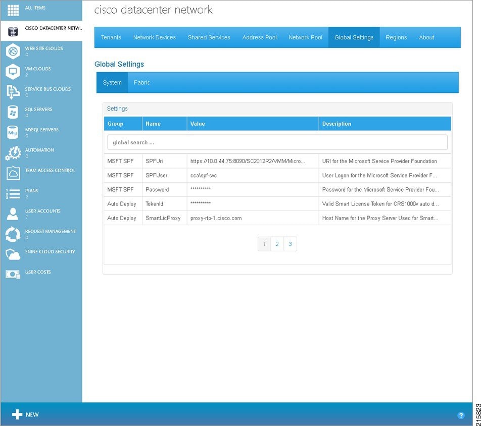
Step 2![]() Move the cursor over the first row of the settings table to highlight the row. Click the highlighted row.
Move the cursor over the first row of the settings table to highlight the row. Click the highlighted row.
You see a pop-up window, as shown in the following screen.
Figure 1-26 Global System Settings Screen—Parameter Pop-up Window
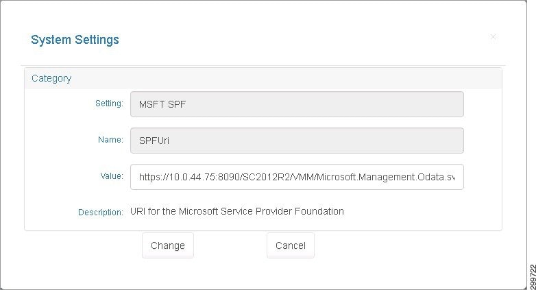
Step 3![]() You can specify or change the value for the parameter. When you are finished, click Change. Click Cancel to return to the previous screen without entering/changing any values.
You can specify or change the value for the parameter. When you are finished, click Change. Click Cancel to return to the previous screen without entering/changing any values.
Step 4![]() Highlight each row in turn and specify or change the value for each parameter in the pop-up windows. When you are finished with the parameters on the first screen, click 2 at the bottom of the screen to see the next set of values.
Highlight each row in turn and specify or change the value for each parameter in the pop-up windows. When you are finished with the parameters on the first screen, click 2 at the bottom of the screen to see the next set of values.
There are several screens where you can specify/change System Global Settings. Table 1-2 describes the various fields and their possible values.
|
|
|
|
|
https://{ spf-server-name }:8090/SC2012/{provider-service}/{subscription-id}/Microsoft.Management.Odata.svc/ |
|||
Valid Smart License Token for Cisco CRS1000V auto deployment |
|||
Host Name for the Proxy Server Used for Smart Licensing Validation |
|||
TCP Port for the Proxy Server Used for Smart Licensing Validation |
|||
Administrator User Logon set at BOOTSTRAP of the Cisco CSR 1000V |
|||
Administrator Password set at BOOTSTRAP of the Cisco CSR 1000V. You can change the password when initially defining global settings. Follow good security practices to set a secure password. However once you have onboarded devices, you cannot change the password since that will cause container creation to fail. |
|||
|
1.The values shown are examples. Use values appropriate for your cloud environment. |
Starting the Cisco.Network.Provisioner Windows Service
The Cisco.Network.Provisioner Windows Service is installed as part of the Cisco CNAP installation process, however it is not started automatically since the Global System settings must first be set.
At this point, starting the Cisco.Network.Provisioner Windows Service loads all the global settings into the Cisco CNAP backend orchestrator and creates the Cloud record(s).
To start the Cisco.Network.Provisioner Windows Service:
Step 1![]() Start Windows Task Manager.
Start Windows Task Manager.
Note![]() You can also use the Windows Start menu to search for Windows services.
You can also use the Windows Start menu to search for Windows services.
Step 2![]() Click the Services tab.
Click the Services tab.
Step 3![]() In the list of services, locate Cisco.Network.Provisioner, right-click it, and in the pop-up window that appears, click Start.
In the list of services, locate Cisco.Network.Provisioner, right-click it, and in the pop-up window that appears, click Start.
Removing an Installation
If you initially install one or two features, you cannot rerun the installer to install the remaining features you did not initially install. You must first remove the initial installation.
Not enabled in the current release: If you find anomalies in your installation, you should first try to repair the installation to see if the anomalies are resolved. If the repair does not resolve the problems, first remove the installation and then reinstall it.
After an installation, if you double-click the CiscoCloudNetworkAutomationProvisioner.msi Windows installer package, you see the Change, Repair, or Remove Installation screen.
Figure 1-27 Change, Repair, or Remove Installation Screen
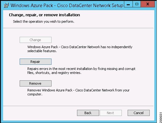
Note![]() The Change button is not active for the reason indicated on the screen.
The Change button is not active for the reason indicated on the screen.
Repairing an Installation
Note![]() Not enabled in the current release.
Not enabled in the current release.
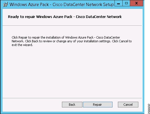
Step 1![]() To repair an installation, click Repair. You see the Ready to Repair an Installation screen.
To repair an installation, click Repair. You see the Ready to Repair an Installation screen.
Figure 1-28 Ready to Repair an Installation Screen
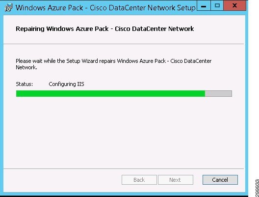
You see a screen with a status bar and messages indicating the progress of the installation repair.
Figure 1-29 Progress of Installation Repair Screen
When the repair completes, you see the Repair Complete screen.
Figure 1-30 Repair Complete Screen
Removing an Installation
Note![]() Put a note about WAP Express v/s DIstributed WAP install. In a WAP Express installation, all components are installed on the same machine so you only need to run remove once. In a WAP Distributed installation, you must remove the components from all individual servers
Put a note about WAP Express v/s DIstributed WAP install. In a WAP Express installation, all components are installed on the same machine so you only need to run remove once. In a WAP Distributed installation, you must remove the components from all individual servers
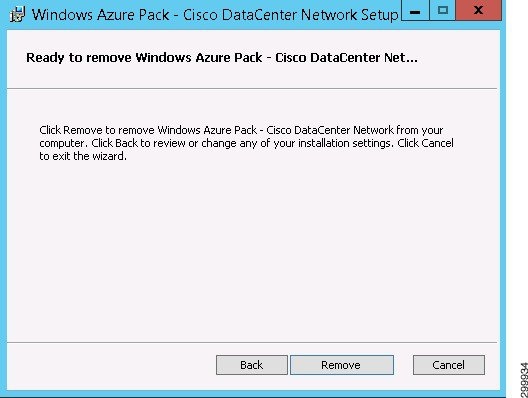
Step 1![]() To remove an installation, click Remove. You see the Ready to Remove an Installation screen.
To remove an installation, click Remove. You see the Ready to Remove an Installation screen.
Figure 1-31 Ready to Remove an Installation Screen
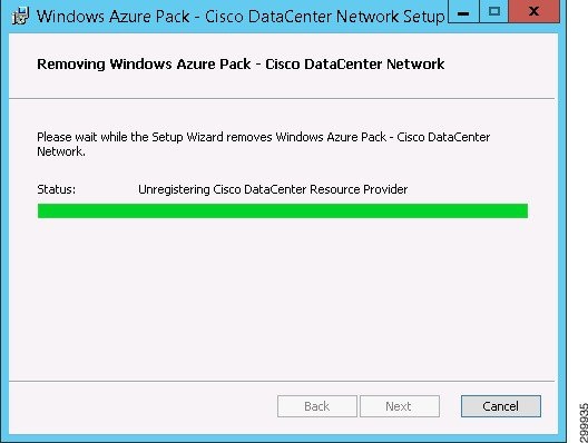
You see a screen with a status bar and messages indicating the progress of the installation removal.
Figure 1-32 Progress of Installation Removal Screen
When the removal completes, you see the Remove Complete screen.
Figure 1-33 Remove Complete Screen
Installing Cisco Network Services Orchestrator Enabled by Tail-f
Note![]() You must install version 4.1.1.
You must install version 4.1.1.
This is a summary of the Cisco NSO installation process. For more detailed information, when the Cisco NSO tar file is expanded, there is a documentation folder containing various documents that you should consult (/opt/ncs/current/doc/pdf).
Note![]() Refer to the Cisco NSO High Availability (HA) deployment guide to set up Cisco NSO in HA mode. The HA guide is part of the tailf-hcc High Availability Framework package.
Refer to the Cisco NSO High Availability (HA) deployment guide to set up Cisco NSO in HA mode. The HA guide is part of the tailf-hcc High Availability Framework package.
Note![]() When onboarding a Cisco APIC on the Network Devices tab in the Admin Portal, the Cisco APIC expects the same Linux username and password credentials as those of the Cisco NSO. You must ensure such a Linux user exists on the Cisco NSO.
When onboarding a Cisco APIC on the Network Devices tab in the Admin Portal, the Cisco APIC expects the same Linux username and password credentials as those of the Cisco NSO. You must ensure such a Linux user exists on the Cisco NSO.
Note![]() Before you onboard a Cisco APIC on the Network Devices tab in the Admin Portal, you must create a directory to store the Cisco APIC configurations. As the admin user (or ensure the admin user has read and write access to the directory), create the directory:
Before you onboard a Cisco APIC on the Network Devices tab in the Admin Portal, you must create a directory to store the Cisco APIC configurations. As the admin user (or ensure the admin user has read and write access to the directory), create the directory:
/home/admin/cisco-apicdc
Installing Required Network Element Drivers
Note![]() You should always consult the Release Notes for Cisco Cloud Network Automation Provisioner for the Microsoft Cloud Platform, Release 2.1 to obtain the most up-to-date list of required network element drivers (NEDs).
You should always consult the Release Notes for Cisco Cloud Network Automation Provisioner for the Microsoft Cloud Platform, Release 2.1 to obtain the most up-to-date list of required network element drivers (NEDs).
Consult the Cisco NSO documentation for instructions on installing NEDs.
|
|
|
Note![]() Whenever you update the NEDs, you should issue the following command to restart Cisco NSO service:
Whenever you update the NEDs, you should issue the following command to restart Cisco NSO service:
# /etc/init.d/ncs restart-with-package-reload
Connecting Cisco Cloud Network Automation Provisioner to the Cisco Network Services Orchestrator
Allowing Manual Configuration Changes on Devices Managed by Cisco CNAP
All devices managed by Cisco CNAP are registered with Cisco NSO, including the Cisco APIC, WAN PEs, and Cisco ASA firewalls. Cisco CNAP maintains a copy of device configurations in a Configuration Database (CDB), which is a component of Cisco NSO. By default Cisco NSO monitors the configurations of devices and expects them to be synchronized with the configurations in its CDB. Configuration synchronization is checked before configuration changes and if an out-of-synchronization condition is detected, an error condition will occur. When Cisco NSO is run in this default mode, all configuration changes on devices in Cisco NSO have to be pushed via the Cisco NSO interface. Manually configuring any device directly through its native interface, such as CLI, will cause Cisco NSO to error out and stop all automated provisioning via Cisco CNAP.
Since some configuration may need to be done on data center network infrastructure devices outside of Cisco CNAP and SP administrators may prefer to directly configure devices using native interfaces, such as CLI, instead of the Cisco NSO interface, a command must be issued to not require the Cisco NSO CDB to be kept in synchronization with the entire configuration of the device. To be able to configure a device from both Cisco CNAP (via Cisco NSO) and directly from its native interface, the out-of-sync-commit-behavior parameter must be set to accept in Cisco NSO, which lets Cisco NSO push configurations to devices even if they are out of synchronization.
Note![]() To avoid Cisco CNAP errors and malfunctions, direct manual configuration changes to devices must be carefully performed to avoid interference with Cisco CNAP-pushed configurations.
To avoid Cisco CNAP errors and malfunctions, direct manual configuration changes to devices must be carefully performed to avoid interference with Cisco CNAP-pushed configurations.
The out-of-sync-commit-behavior parameter is a Cisco NSO global setting which applies to all devices added in Cisco NSO. Manually issue the following command on the Cisco NSO immediately after installing Cisco NSO and before adding Cisco NSO to Cisco CNAP.
Note![]() Since Cisco CNAP is also pushing configurations for the automation of work flows on devices, certain precautions need to be followed when manually configuring devices to avoid disrupting Cisco CNAP-based automation. Changing configurations pushed from Cisco CNAP will cause the automated provisioning system to malfunction, which in some cases could cause all automated provisioning to stop until the error conditions are manually remediated. In general on the data center provider edge, all configurations under the tenant VRFs pushed by Cisco CNAP should not be edited or changed, including sub-interfaces and routing. Similarly on the Cisco APIC, the Cisco APIC tenants configured by Cisco CNAP should only be changed by Cisco CNAP. Any configurations pushed by Cisco CNAP should not be manually edited.
Since Cisco CNAP is also pushing configurations for the automation of work flows on devices, certain precautions need to be followed when manually configuring devices to avoid disrupting Cisco CNAP-based automation. Changing configurations pushed from Cisco CNAP will cause the automated provisioning system to malfunction, which in some cases could cause all automated provisioning to stop until the error conditions are manually remediated. In general on the data center provider edge, all configurations under the tenant VRFs pushed by Cisco CNAP should not be edited or changed, including sub-interfaces and routing. Similarly on the Cisco APIC, the Cisco APIC tenants configured by Cisco CNAP should only be changed by Cisco CNAP. Any configurations pushed by Cisco CNAP should not be manually edited.
Connecting Cisco CNAP to Cisco NSO
Note![]() To support Cisco CSR 1000V IOS XE Software Versions 03.16 and 03.17, you have to add another global setting on the Cisco NSO:
To support Cisco CSR 1000V IOS XE Software Versions 03.16 and 03.17, you have to add another global setting on the Cisco NSO:
set devices global-settings read-timeout 60
Note![]() All global settings done on the Cisco NSO in HA mode need to be executed on all master and slave nodes in the HA cluster.
All global settings done on the Cisco NSO in HA mode need to be executed on all master and slave nodes in the HA cluster.
To connect Cisco CNAP to Cisco NSO, you must add the Cisco NSO in the Admin Portal. The Cisco NSO should be the first network device you add.
Step 1![]() Access WAP as an administrator.
Access WAP as an administrator.
For information on accessing WAP, see the WAP documentation.
Step 2![]() In the WAP interface, in the left column, click Cisco Datacenter Network.
In the WAP interface, in the left column, click Cisco Datacenter Network.
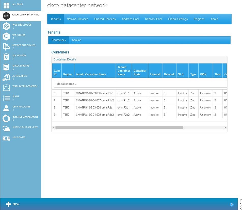
You see the main Cisco Datacenter Network screen, which is the Tenants tab, as shown in the following screen.
Figure 1-34 Tenants Tab Screen
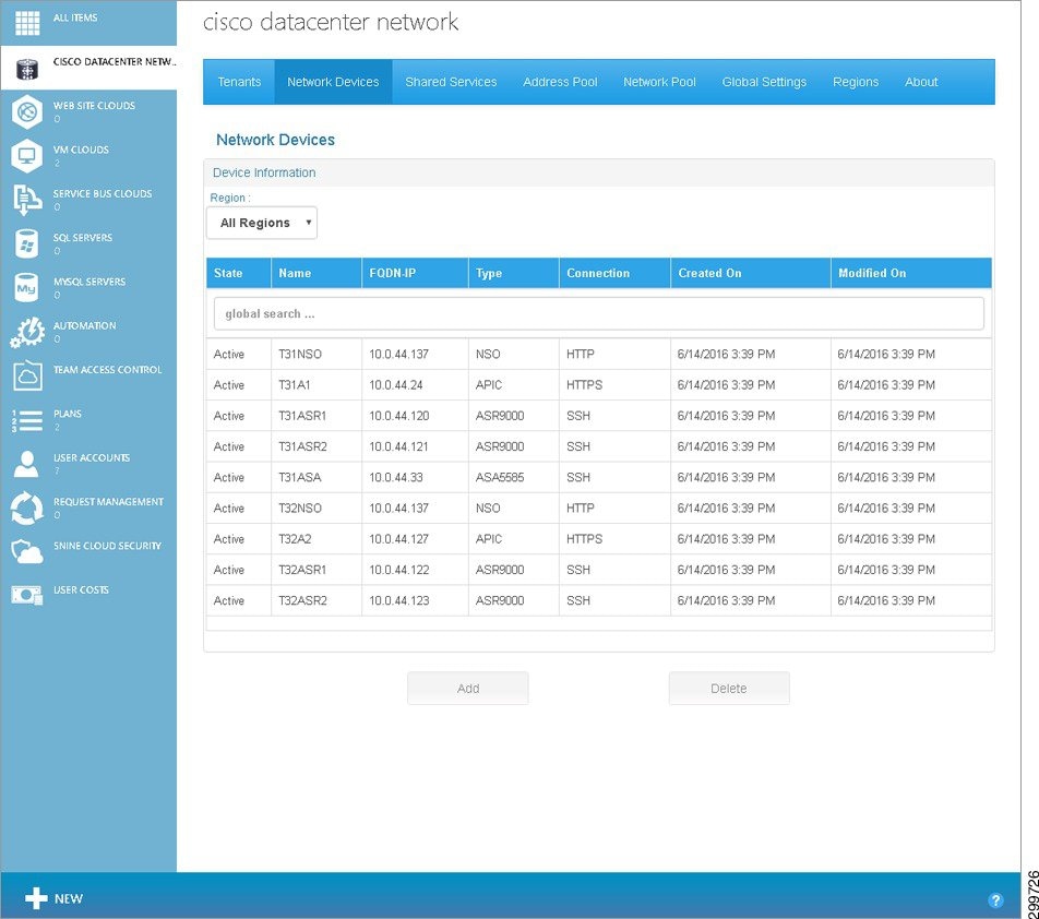
Step 3![]() Click Network Devices and on the Network Devices Tab screen, in the Cloud drop-down, click the cloud service to which you want to add a device, as shown in the following screen.
Click Network Devices and on the Network Devices Tab screen, in the Cloud drop-down, click the cloud service to which you want to add a device, as shown in the following screen.
Figure 1-35 Network Devices Tab Screen
You see the Add Network Device screen.
Figure 1-36 Add Network Device Screen
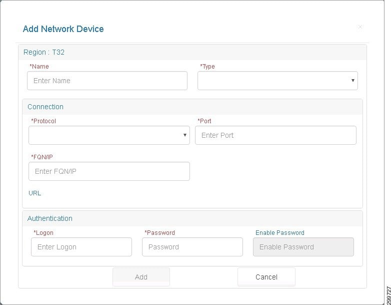
Step 5![]() Cloud: Cloud Name displays the Cloud Service to which the Cisco NSO will be associated. Complete the following fields:
Cloud: Cloud Name displays the Cloud Service to which the Cisco NSO will be associated. Complete the following fields:
- Name—User-defined name given to the Network Device.
- Type—Device type: On the pull-down menu, select NSO.
- Connection:
–![]() Protocol—Protocol used to connect to the device: SSH, HTTP, or HTTPS.
Protocol—Protocol used to connect to the device: SSH, HTTP, or HTTPS.
–![]() Port—Port used to establish the connection to the device.
Port—Port used to establish the connection to the device.
–![]() FQDN/IP—Valid IP Address in dotted format or Fully Qualified Name (FQN) given to the Network Device at the Provider’s Network. Characters, numbers, and “-”. (The period [.] is also used in DNS names, but only between DNS labels and at the end of an FQDN.) https://technet.microsoft.com/en-us/library/cc959336.aspx
FQDN/IP—Valid IP Address in dotted format or Fully Qualified Name (FQN) given to the Network Device at the Provider’s Network. Characters, numbers, and “-”. (The period [.] is also used in DNS names, but only between DNS labels and at the end of an FQDN.) https://technet.microsoft.com/en-us/library/cc959336.aspx
–![]() Login—Service Account Logon used to establish a connection with the Network Device.
Login—Service Account Logon used to establish a connection with the Network Device.
–![]() Password—Service account password. The entry field on the dialog must be set to show a “*” for each character entered for password.
Password—Service account password. The entry field on the dialog must be set to show a “*” for each character entered for password.
–![]() Enable Password—If the Cisco NSO you are adding has an enable password that is different than the device password, enter it here. Otherwise the device password will be used for enable mode.
Enable Password—If the Cisco NSO you are adding has an enable password that is different than the device password, enter it here. Otherwise the device password will be used for enable mode.
Step 6![]() Click Add to add the Cisco NSO or Cancel to cancel the addition.
Click Add to add the Cisco NSO or Cancel to cancel the addition.
Connecting Cisco Cloud Network Automation Provisioner to Managed Devices
In addition to connecting Cisco CNAP to Cisco NSO, you must also add other devices in the Admin Portal, such as the Cisco ASR9000, Cisco APIC, etc.
For more information, see Cisco Cloud Network Automation Provisioner for the Microsoft Cloud Platform—Admin Portal Guide, Release 2.1.
Post-Installation Verification Overview
The following table summarizes the verification process for the various components.


Using Cisco Cloud Network Automation Provisioner
You access the Admin Portal and Tenant Portal from the WAP interface.
Accessing the Admin Portal
Step 1![]() Access the WAP Admin Site and log in as an administrator.
Access the WAP Admin Site and log in as an administrator.
For information on accessing WAP, see the WAP documentation.
Step 2![]() In the WAP Admin Site, in the left column, click Cisco Datacenter Network.
In the WAP Admin Site, in the left column, click Cisco Datacenter Network.
You see the main Cisco Datacenter Network screen, which is the Tenants tab, as shown in the following screen.
Figure 1-37 Tenants Tab Screen
Accessing the Tenant Portal
Step 1![]() Access the WAP Tenant Site.
Access the WAP Tenant Site.
For information on accessing WAP, see the WAP documentation.
You see the WAP Tenant Portal Login screen, as shown in the following screen.
Figure 1-38 WAP Tenant Portal Login Screen
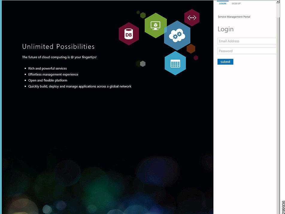
Step 2![]() Enter your login credentials, then click submit.
Enter your login credentials, then click submit.
You see the Tenant Portal main screen, as shown in the following screen.
Figure 1-39 Tenant Portal Main Screen
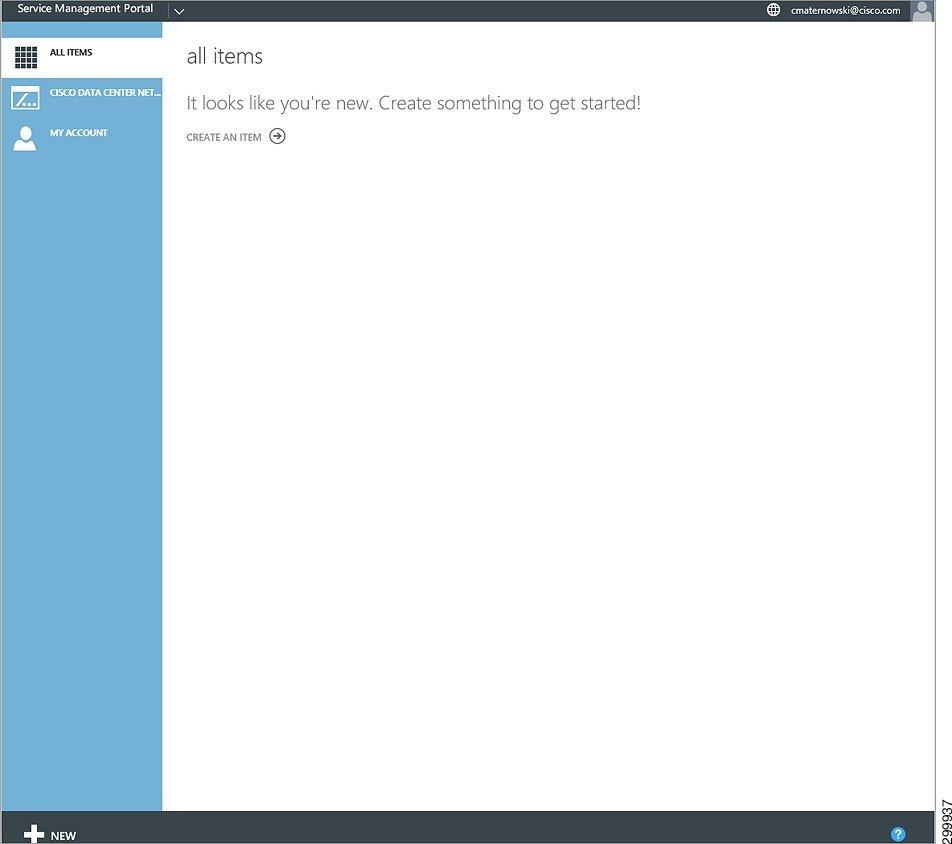
Step 3![]() In the WAP interface, in the left column, click Cisco Datacenter Network.
In the WAP interface, in the left column, click Cisco Datacenter Network.
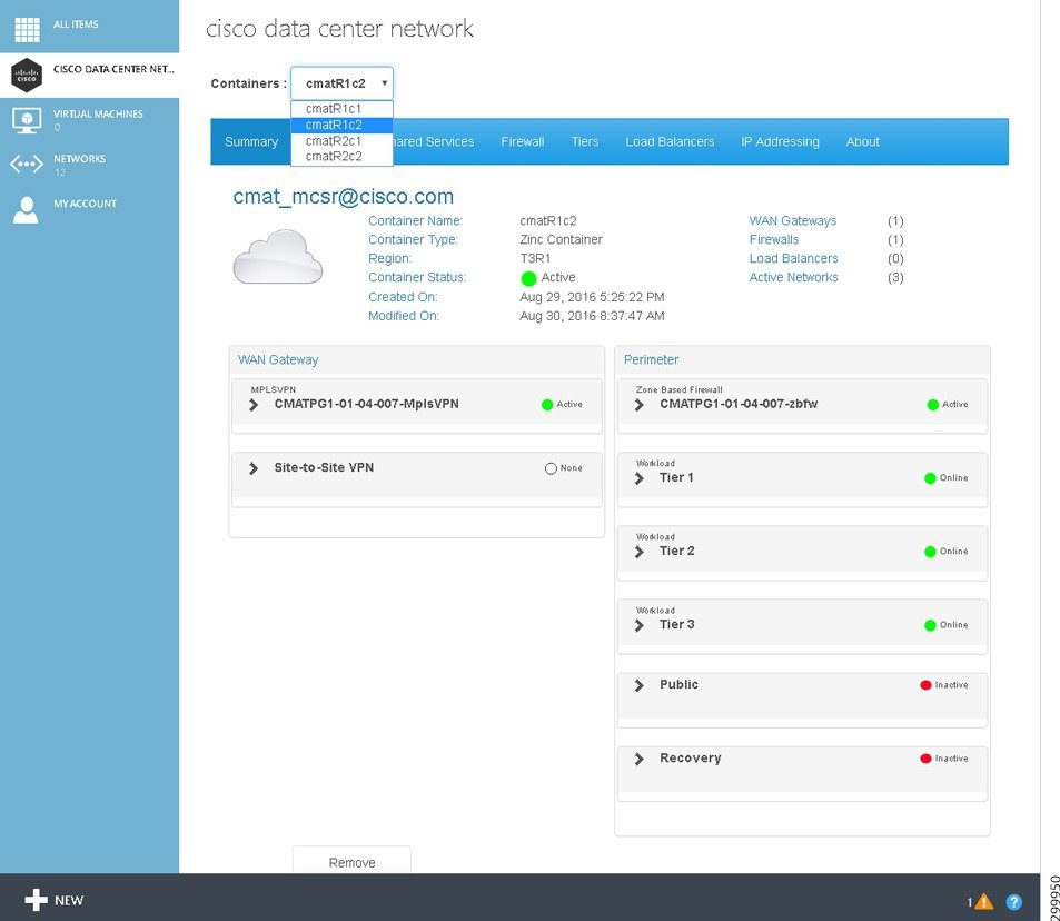
You see the main Cisco Datacenter Center screen, as shown in the following screen.
Figure 1-40 Tenant Portal Cisco Datacenter Network Screen
Appendix A—Using a Script to Install Cisco Cloud Network Automation Provisioner
You can use the VBScript script packaged with Cisco CNAP to install it. The advantage of using a script is that you can specify various parameters, such as run in quiet mode, produce logs that can be useful in debugging installation issues, etc.
Running this script first removes all previous installations of the Cisco CNAP and then installs the specified instance.
Run the script, which is named setup.vbx, via the administrator command line to quickly install Cisco CNAP with predefined values you specify.
The arguments to the script are as follows (all values are case sensitive):
- /feature:{ backend / admin / tenant / all }—Select the feature(s) you want to install. There is no default. If you do not specify a /feature argument, then the script runs the standard installer and launches the GUI with no options selected, but with logging enabled.
- /quiet:{ true / false }—Choose to run the installer silently or not. If the installer runs silently, you do not see any installer GUI screen. The default is false.
- /iniFile:< path to.ini file >—Specify an.ini file that contains values for the various parameters required to install the backend service (the install script currently only supports specifying values for the backend service feature). There is no default value. See Installing the Admin Site for the various values that have to be specified. The format of the.ini file should follow that of the example ini file provided with the installer package.
Appendix B—Troubleshooting Installation Issues
Accessing Logs and Identifying Issues
Installation logs are not produced when using the GUI to install Cisco CNAP. However you can use a script packaged with Cisco CNAP to install it; the script. produces logs that can be useful in debugging installation issues. For more information, see Appendix A—Using a Script to Install Cisco Cloud Network Automation Provisioner.
Contacting Customer Support
Troubleshooting Microsoft Windows Azure Pack
For information on troubleshooting Microsoft WAP, see:
Also see the list of references in the section Useful Microsoft Windows Azure Pack References.
 Feedback