Services Implementation
Please refer to the Service Tiers section for the different services offered to different types of tenants, Gold, Silver, Bronze, and Copper. This section discusses the implementation on the services nodes, the Application Control Engine (ACE) 4710 for Server Load Balancing (SLB), the Adaptive Security Appliance (ASA) 5585-based perimeter firewall, the ASA 5555-x-based VPN access, and the Virtual Security Gateway (VSG) for the virtualized compute firewall.
•![]() Services Best Practices and Caveats
Services Best Practices and Caveats
ACE 4710 Appliance
This section presents the following topics:
ACE Redundancy Configuration
The ACE appliances used in this solution are configured in active/active redundancy mode, i.e., a pair of ACE appliances forming a Fault-Tolerant (FT) peer will forward traffic for different contexts. To provide redundancy, a FT VLAN is configured on both ACE appliances. This FT VLAN is used by the ACE appliances to send state information, replication data redundancy protocol packets, heartbeat packets, and configuration synchronization packets. For the ACE appliances, the FT VLAN should be trunked using the ft-port vlan <vlan-id> command. This identifies a FT VLAN on a trunk port and ensures that proper QoS treatment is applied to packets on that VLAN. Proper QoS treatment ensures that FT messages between peers are not dropped in the network. The Nexus 7000 devices are also configured to ensure that proper QoS treatment is given to FT packets.
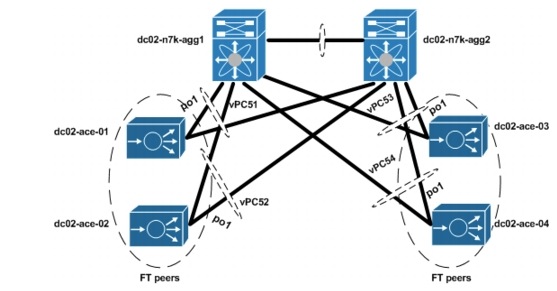
In this solution, the ACE appliance FT packets are switched through the Layer 2 (L2) network. The ACE FT peer connects to the L2 network through port-channels with all four Gigabit Ethernet interfaces as members. The endpoints of these port-channels are vPCs on a pair of Nexus 7000 switches. Based on L2 forwarding rules on the Nexus 7000 switches, redundancy packets of the ACE received by a Nexus 7000 switch will be switched to the vPC that connects to the other ACE
FT peer. It will be rare for the redundancy packets to transverse any other link, especially the Nexus 7000 vPC peer links. Figure 5-1 shows the L2 connection between the ACE appliances and the Nexus 7000 switches. A single management VLAN is used to manage the four ACE appliances used in this solution. To avoid MAC collision, each of the ACE appliances are assigned a different shared-vlan hostid to ensure that they derive their MAC addresses from a different MAC address pool. The ACE modules and appliances are built with 16 pools of MAC addresses.
Figure 5-1 ACE-Nexus 7000 Topology
Below is a sample configuration required for ACE redundancy.
shared-vlan-hostid 3
peer shared-vlan-hostid 4
context customer_silver1
allocate-interface vlan 60
allocate-interface vlan 501
allocate-interface vlan 601
allocate-interface vlan 701
member silver-sticky-class
ft peer 1
heartbeat interval 1000
heartbeat count 10
ft-interface vlan 1998
ft group 31
peer 1
priority 255
peer priority 120
associate-context customer_silver1
inservice
interface port-channel 1
ft-port vlan 1998
  switchport trunk allowed vlan
60,201-210,301-310,401-410,501-520,601-620,701-720,1601-1610
port-channel load-balance src-dst-port
ACE Context Distribution
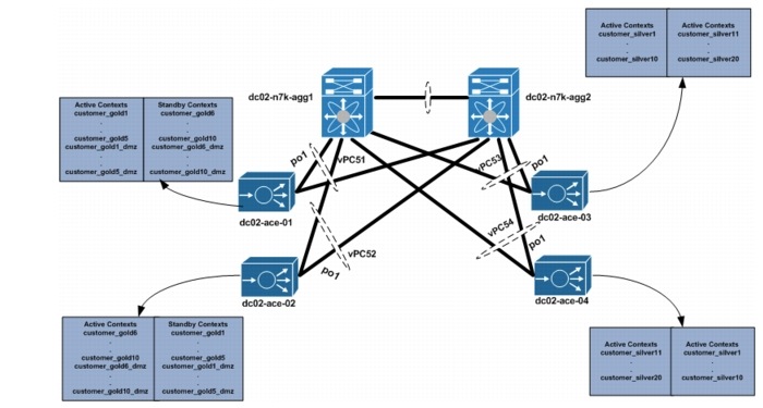
A total of 40 contexts are used in this validation. In this solution, each Gold tenant network configuration is validated with two ACE contexts. One ACE context is used to load balance tenant Private, or PVT, server resources, and the other ACE context is used to load balance Demilitarized Zone (DMZ) server resources. A single ACE context is assigned to each Silver tenant. Two ACE 4710 appliance are used for Gold tenants, while two other ACE 4710s are used for Silver tenants. The ACEAP-04-LIC licenses are installed in each appliance. This license type allows the system to reach the context and throughput limits of each appliance. The number of ACE appliances can be increased to accommodate more Gold/Silver tenants.
Figure 5-2 shows the ACE context distribution used in this solution. For effective load balancing and redundancy, half of each tenant type is active in each of the ACE 4710s assigned to that tenant type, while the other half will be standby on the other ACE 4710 appliance.
Figure 5-2 ACE Context Distribution
ACE SLB Configuration
The ACE contexts for the tenants are configured in a one-arm mode. Using this mode, the ACE data interfaces are in the same VLAN with that of the servers. In this implementation, the ACE VIP addresses are also chosen to be in the same server subnet. This eliminates the need to have additional static routes on the Nexus 7000 aggregation switches. Each ACE context is configured with a default route pointing to the VLAN interface of the Nexus 7000. Client addresses are translated to addresses in the same server subnet to ensure load-balanced return traffic goes to the ACE context. Each ACE context is configured to load balance Layer 4 (L4) - Layer 7 (L7) traffic. L4 load-balancing policies are configured for User Datagram Protocol (UDP) traffic, while L7 load-balancing policies are configured for Hypertext Transfer Protocol (HTTP) traffic.
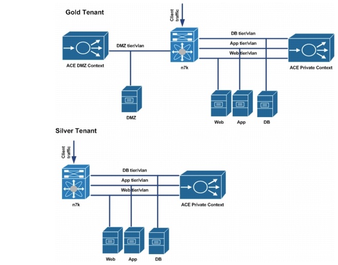
In this implementation, each Gold and Silver ACE private context is configured to load balance web client traffic, web tier traffic directed to the app tier VIP, and app tier traffic directed to the Database (DB) tier VIP address. An ACE DMZ context is configured for each Gold tenant to load balance traffic destined to the DMZ servers.
Figure 5-3 shows the ACE SLB topology for Gold and Silver tenants.
Figure 5-3 Figure 5-3. Gold and Silver ACE Context
The following sections show the ACE SLB configurations.
Rserver Configuration
The rserver configuration is used to associate the real server IP address to an object name. This object name is the rserver name and will be used to define members of a server farm. A sample configuration is shown below.
Sample Rserver Configuration
rserver host web-server1
ip address 11.1.1.11
inservice
rserver host web-server2
ip address 11.1.1.12
inservice
rserver host web-server3
ip address 11.1.1.13
inservice
Server Farm Configuration
The server farm is a set of real servers providing the same application service. Client traffic is load balanced among the real servers in a server farm using a predictor algorithm. By default, the predictor used is round robin and this is used in this solution. The server farm configuration also provide a convenient way to take real servers offline or bring real servers online. Real servers information is added into the server farm configuration using their associated rserver names. In addition, probes can be applied to a server farm to ensure that the VIP addresses are taken offline if there is no real server available to handle requests. A sample configuration is shown below.
serverfarm host app-serverfarm
rserver app-server1
inservice
rserver app-server2
inservice
rserver app-server3
inservice
serverfarm host db-serverfarm
rserver db-server1
inservice
rserver db-server2
inservice
rserver db-server3
inservice
serverfarm host udp-serverfarm
rserver udp-host
inservice
serverfarm host udp-serverfarm:30000
rserver udp-host:30000
inservice
serverfarm host web-serverfarm
rserver web-server1
rserver web-server2
rserver web-server3
rserver web-spirent
inservice
Class-Maps
Management, L4, and L7 class-maps are used in the configuration. The Management class-map defines management related traffic that is allowed to the ACE contexts. L4 class-maps are used to define the L4 ports that are used as match criteria for client traffic that will be load balanced. Typically, UDP and Transmission Control Protocol (TCP) ports are used as match criteria. L7 class-maps are used to define the L7 header values that will be used as match criteria for load balancing. In this implementation, HTTP URL values are used to define criteria. A sample configuration used in this solution is shown below.
Sample Management Class-map
class-map type management match-any management-traffic
2 match protocol ssh any
3 match protocol http any
4 match protocol https any
5 match protocol icmp any
6 match protocol telnet any
7 match protocol snmp source-address 192.168.0.0 255.255.0.0
Sample L4 Class-map
class-map match-all udp-vip
2 match virtual-address 11.1.1.111 udp eq 69
class-map match-all udp-vip:30000
2 match virtual-address 11.1.1.111 udp eq 30000
class-map match-all web->app-vip
2 match virtual-address 11.1.2.111 tcp eq www
class-map match-all web-vip
2 match virtual-address 11.1.1.111 tcp eq www
class-map match-all app->db-vip
2 match virtual-address 11.1.3.111 tcp eq www
Sample L7 Class-map
class-map type http loadbalance match-any cm-app-subnet
2 match source-address 11.1.2.0 255.255.255.0
class-map type http loadbalance match-any cm-http
2 match http url /.*.txt
3 match http url /.*.html
class-map type http loadbalance match-any cm-web-subnet
2 match source-address 11.1.1.0 255.255.255.0
class-map type http loadbalance match-all cm-app->db
2 match class-map cm-http
3 match class-map cm-app-subnet
class-map type http loadbalance match-all cm-web->app
2 match class-map cm-http
3 match class-map cm-web-subnet
NAT Configuration
Either Source NAT with PAT (SNAT) or Policy Based Routing (PBR) are used to implement the one-arm ACE topology. In this solution, we use SNAT with PAT to implement the one-arm ACE configuration. This involves the ACE translating the client source address to an address in a pool to ensure that client return traffic from the server farm is received by the ACE appliance. We use a server farm subnet address range to define the NAT pool, and this eliminates the need to have static routes on the Nexus 7000 switches. The server receiving the client traffic will have an ARP entry that it receives from the ACE context. We use PAT to ensure that we do not quickly deplete the pool when client requests are received. The NAT pool is defined on the interface, and this NAT pool is associated with an L4 policy-map. A sample configuration used in this solution is shown below.
Sample NAT configuration
interface vlan 201
description web tier
ip address 11.1.1.22 255.255.255.0
alias 11.1.1.21 255.255.255.0
peer ip address 11.1.1.23 255.255.255.0
access-group input web-acl
nat-pool 1 11.1.1.24 11.1.1.30 netmask 255.255.255.0 pat
nat-pool 11 11.1.1.41 11.1.1.41 netmask 255.255.255.255
nat-pool 12 11.1.1.42 11.1.1.42 netmask 255.255.255.255
service-policy input lb-policy
no shutdown
interface vlan 301
description app tier
ip address 11.1.2.22 255.255.255.0
alias 11.1.2.21 255.255.255.0
peer ip address 11.1.2.23 255.255.255.0
access-group input app-acl
nat-pool 2 11.1.2.24 11.1.2.30 netmask 255.255.255.0 pat
service-policy input web->app-lb
no shutdown
interface vlan 401
description db tier
ip address 11.1.3.22 255.255.255.0
alias 11.1.3.21 255.255.255.0
peer ip address 11.1.3.23 255.255.255.0
access-group input db-acl
nat-pool 3 11.1.3.24 11.1.3.30 netmask 255.255.255.0 pat
service-policy input app->db-lb
no shutdown
Policy-Maps
Management, L4, and L7 policy-maps are used in the configuration. The Management policy-map defines the action that will be taken if there is a match in the management class-map. The L4 load-balance policy combines the L4 class-map with an L7 load-balance policy. This L4 load-balance policy defines what traffic should be load balanced and what load-balance policy should be applied to this traffic. The load-balance policy applied to matched traffic is defined by the L7 load-balance policy. This policy defines L7 match criteria for received traffic and the server farm that handles L7 traffic. L4 polices are applied to data interfaces on the ACE context using the service-policy. The sample configurations used in this solution are shown below.
Sample Management Configuration
policy-map type management first-match management-traffic
class management-traffic
permit
Sample L7 Policy-map
policy-map type loadbalance first-match app->db-lb-policy
class cm-app->db
sticky-serverfarm customer_gold1-app->db
policy-map type loadbalance first-match udp-lb-policy
class class-default
serverfarm udp-serverfarm
policy-map type loadbalance first-match udp-lb-policy:30000
class class-default
serverfarm udp-serverfarm:30000
policy-map type loadbalance first-match web->app-lb-policy
class cm-web->app
sticky-serverfarm customer_gold1-web->app
policy-map type loadbalance first-match web-lb-policy
class cm-http
sticky-serverfarm customer_gold1-http
Sample L4 Policy-map
policy-map multi-match app->db-lb
class app->db-vip
loadbalance vip inservice
loadbalance policy app->db-lb-policy
loadbalance vip icmp-reply active
nat dynamic 3 vlan 401
policy-map multi-match lb-policy
class web-vip
loadbalance vip inservice
loadbalance policy web-lb-policy
loadbalance vip icmp-reply active
nat dynamic 1 vlan 201
connection advanced-options tcp_pm
class udp-vip
loadbalance vip inservice
loadbalance policy udp-lb-policy
loadbalance vip icmp-reply
nat dynamic 11 vlan 201
connection advanced-options udp_pm
class udp-vip:30000
loadbalance vip inservice
loadbalance policy udp-lb-policy:30000
loadbalance vip icmp-reply active
nat dynamic 12 vlan 201
connection advanced-options udp_pm
policy-map multi-match web->app-lb
class web->app-vip
loadbalance vip inservice
loadbalance policy web->app-lb-policy
loadbalance vip icmp-reply active
nat dynamic 2 vlan 301
ACE SLB Traffic Path Overview
Figure 5-3 shows the ACE SLB traffic path overview.
Figure 5-4 ACE SLB Traffic Path Overview
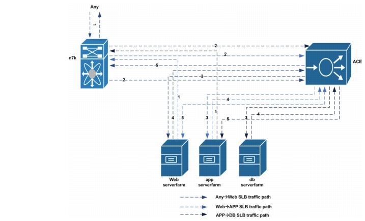
AnyWeb VIP Traffic Path
1. ![]() Traffic destined to the web VIP is received from Gold and Silver tenant client networks.
Traffic destined to the web VIP is received from Gold and Silver tenant client networks.
2. ![]() Traffic destined to the web VIP will be forwarded by the Nexus 7000 aggregation routers (on the same web VLAN) to the ACE context.
Traffic destined to the web VIP will be forwarded by the Nexus 7000 aggregation routers (on the same web VLAN) to the ACE context.
3. ![]() At the ACE context, client traffic is load balanced to the server in the server farm that will handle the client request.
At the ACE context, client traffic is load balanced to the server in the server farm that will handle the client request.
4. ![]() The return traffic from the web server will be forwarded to the ACE context.
The return traffic from the web server will be forwarded to the ACE context.
5. ![]() The ACE context will forward the client to its gateway, which is an HSRP VIP address on the Nexus 7000 aggregation router.
The ACE context will forward the client to its gateway, which is an HSRP VIP address on the Nexus 7000 aggregation router.
Web—APP VIP Traffic Path
1. ![]() Traffic destined to the app VIP from a web server, will be forwarded to the web server gateway which is the nexus 7000 aggregation router
Traffic destined to the app VIP from a web server, will be forwarded to the web server gateway which is the nexus 7000 aggregation router
2. ![]() the nexus 7000 aggregation router will forward this traffic to the ACE context. Both nexus 7000 aggregation router and the ACE Context app interface are in the same VLAN
the nexus 7000 aggregation router will forward this traffic to the ACE context. Both nexus 7000 aggregation router and the ACE Context app interface are in the same VLAN
3. ![]() At the ACE context, web server traffic is load balanced to a server in the app server farm.
At the ACE context, web server traffic is load balanced to a server in the app server farm.
4. ![]() The return traffic from the app server will be sent to the ACE context. This is due to the web server address being translated to a pool on the ACE on the same server subnet as the app servers.
The return traffic from the app server will be sent to the ACE context. This is due to the web server address being translated to a pool on the ACE on the same server subnet as the app servers.
5. ![]() The ACE context will send it to the web server that originated the traffic. Return traffic does not reach the nexus 7000 aggregation router.
The ACE context will send it to the web server that originated the traffic. Return traffic does not reach the nexus 7000 aggregation router.
APP—DB VIP Traffic Path
1. ![]() Traffic destined to the DB VIP address from an app server will be forwarded to the app server gateway, which is the Nexus 7000 aggregation router.
Traffic destined to the DB VIP address from an app server will be forwarded to the app server gateway, which is the Nexus 7000 aggregation router.
2. ![]() The Nexus 7000 aggregation router will forward this traffic to the ACE context. Both the Nexus 7000 aggregation router and the ACE context DB interface are in the same VLAN.
The Nexus 7000 aggregation router will forward this traffic to the ACE context. Both the Nexus 7000 aggregation router and the ACE context DB interface are in the same VLAN.
3. ![]() At the ACE context, app server traffic is load balanced to a server in the DB server farm.
At the ACE context, app server traffic is load balanced to a server in the DB server farm.
4. ![]() The return traffic from the DB server will be sent to the ACE context. This is due to the app server address being translated to a pool on the ACE on the same server subnet as the DB servers.
The return traffic from the DB server will be sent to the ACE context. This is due to the app server address being translated to a pool on the ACE on the same server subnet as the DB servers.
5. ![]() The ACE context will send this traffic to the app server that originated the traffic. Return traffic does not reach the Nexus 7000 aggregation router.
The ACE context will send this traffic to the app server that originated the traffic. Return traffic does not reach the Nexus 7000 aggregation router.
Table 5-1 and Table 5-2 provide an overview of Gold and Silver client traffic that will be load balanced. Note that L7 class-maps are used to match allowed HTTP URL and client source address.
Refer to Associating a Layer 7 SLB Policy Map with a Layer 3 and Layer 4 SLB Policy Map for additional information on ACE SLB configuration.
ASA Perimeter Firewall
This section presents the following topics:
•![]() Gold Tenant ASA Firewall Configuration
Gold Tenant ASA Firewall Configuration
ASA Firewall Redundancy
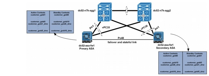
In this implementation, two ASA firewalls are used to provide Gold tenants with security services, e.g., inspection, ACL, NAT, etc., and these firewalls are configured in active/active redundancy mode to maximize their capability. Separate, dedicated interfaces are used for failover and stateful failover interfaces between the ASA firewall. For more information on how to set up ASA firewall redundancy, refer to the following links:
•![]() Configuring Active/Active Redundancy
Configuring Active/Active Redundancy
•![]() VMDC 2.2 Implementation Guide
VMDC 2.2 Implementation Guide
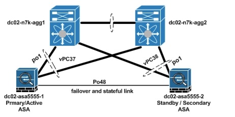
ASA port-channels are used to connect to the Nexus 7000 aggregation switch vPC. The data VLANs used for communication through the ASA are trunked on these interfaces. To protect against single vPC failures, interfaces allocated to firewall tenants should be monitored. This ensures that if a failure occurs, the failure policy condition also occurs. For effective load balancing and redundancy, the tenants' contexts are distributed among the two ASA firewalls used in this solution (Table 5-2).
Figure 5-5 ASA Firewall Setup
Below is the ASA sample firewall failover configuration.
failover
failover lan unit primary
failover lan interface FL Port-channel48.4093
failover polltime unit 5 holdtime 15
failover replication http
failover link SL Port-channel48.4094
failover interface ip FL 9.9.9.1 255.255.255.0 standby 9.9.9.2
failover interface ip SL 9.9.10.1 255.255.255.0 standby 9.9.10.2
failover group 1
preempt
replication http
polltime interface 1 holdtime 5
interface-policy 50%
failover group 2
secondary
preempt
replication http
polltime interface 1 holdtime 5
interface-policy 50%
ASA Failover Configuration Required on context
----------------------------------------------
dc02-asa-fw1/customer-gold1# sh run monitor-interface
monitor-interface inside
monitor-interface outside
monitor-interface dmz
Two failover groups on the ASA are used to distribute active contexts among the primary ASA and the secondary ASA. By default, failover group 1 is assigned to the primary ASA. To have active contexts on the secondary ASA, failover group 2 is assigned to the secondary ASA. To distribute contexts on both ASA devices, half of all configured Gold contexts are assigned to failover group 1, and the other half are assigned to failover group 2. A sample configuration for two Gold tenants is shown below.
ASA Context Configuration
dc02-asa-fw1# sh run context customer-gold1
context customer-gold1
allocate-interface Management0/0
allocate-interface Port-channel1.1201
allocate-interface Port-channel1.1301
allocate-interface Port-channel1.1401
config-url disk0:/vmdc3.1/customer-gold1
join-failover-group 1
!
dc02-asa-fw1# sh run context customer-gold6
context customer-gold6
allocate-interface Management0/0
allocate-interface Port-channel1.1206
allocate-interface Port-channel1.1306
allocate-interface Port-channel1.1406
config-url disk0:/vmdc3.1/customer-gold6
join-failover-group 2
!
Gold Tenant ASA Firewall Configuration
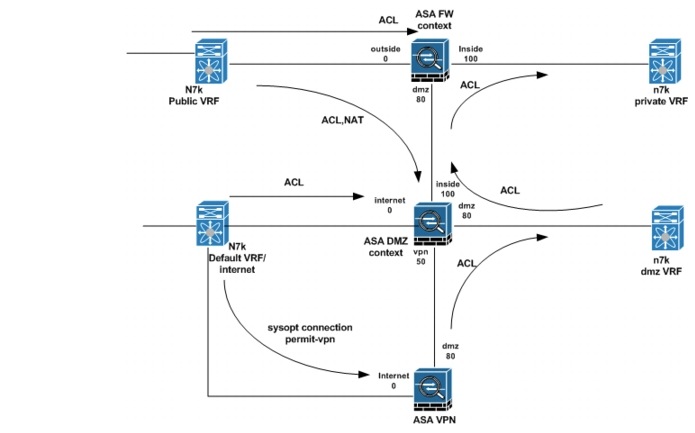
Figure 5-6 provides an overview of a typical ASA firewall configuration for a Gold tenant in this implementation.
Figure 5-6 Gold Tenant ASA Firewall Configuration Overview
Routing Configuration
Refer to ASA Firewall Context Routing Configuration for the configuration required to route through the ASA. To route between the Private and DMZ contexts for a tenant, the mac-address auto prefix <16-bit prefix> command is configured to ensure that all active interfaces on the ASA have a unique MAC address. This configuration is required for inter-context routing on the ASA.
ACL Configuration
ACLs are configured on the Gold tenant ASA firewall context outside interfaces to allow permitted protocol traffic from Service Provider client networks to be forwarded to the inside and DMZ networks. In this implementation, an object group is used to simplify the ACL configuration. Two object-group types are used in the ACL configuration. The network-object group is used to identify the networks to be allowed, while the service-object group is used to identify the UDP and TCP ports that are allowed for these networks. Also, ACLs are applied on the context DMZ interfaces to identify the DMZ server traffic that should be allowed to the private server networks. ACLs are also configured in the DMZ firewall contexts for the tenants. These ACLs control allowed traffic from Internet to DMZ networks.
A sample configuration of a configured object group and ACL is shown below.
dc02-asa-fw1/customer-gold1# sh run object-group
object-group network SP-CLIENTS-NETWORK
network-object 40.1.0.0 255.255.0.0
network-object 10.1.0.0 255.255.0.0
network-object 131.0.0.0 255.0.0.0
object-group service SP-CLIENTS-PROTOCOLS-TCP tcp
port-object eq www
port-object eq https
port-object eq ftp
port-object eq ssh
port-object eq domain
object-group service SP-CLIENTS-PROTOCOLS-UDP udp
port-object eq tftp
port-object eq domain
port-object range 10000 30000
object-group network DMZ-VPN-NETWORK
network-object 11.1.4.0 255.255.255.0
network-object 11.255.0.0 255.255.0.0
object-group service DMZ-VPN-PROTOCOLS-TCP tcp
port-object eq www
port-object eq https
port-object eq ssh
port-object eq ftp
object-group service DMZ-VPN-PROTOCOLS-UDP udp
port-object eq tftp
port-object eq domain
port-object range 10000 30000
dc02-asa-fw1/customer-gold1# sh run access-list
access-list DMZ-VPN extended permit tcp object-group DMZ-VPN-NETWORK any object-group
DMZ-VPN-PROTOCOLS-TCP
access-list DMZ-VPN extended permit udp object-group DMZ-VPN-NETWORK any object-group
DMZ-VPN-PROTOCOLS-UDP
access-list DMZ-VPN extended permit icmp object-group DMZ-VPN-NETWORK any
access-list OUTSIDE extended permit tcp object-group SP-CLIENTS-NETWORK any
object-group SP-CLIENTS-PROTOCOLS-TCP
access-list OUTSIDE extended permit udp object-group SP-CLIENTS-NETWORK any
object-group SP-CLIENTS-PROTOCOLS-UDP
access-list OUTSIDE extended permit icmp object-group SP-CLIENTS-NETWORK any
dc02-asa-fw1/customer-gold1# sh run access-group
access-group OUTSIDE in interface outside
access-group DMZ-VPN in interface dmz
dc02-asa-fw1/customer-gold1#
NAT Configuration
Due to the use of static default routes on tenant contexts, dynamic NAT is configured on the private tenant contexts. To enable the DMZ context, know how to forward return traffic for Service Provider clients from the DMZ networks. This dynamic NAT translates the source IP addresses of Service Provider clients whose traffic is destined to DMZ server network. Static NAT configuration is also added in the DMZ context to translate IP addresses of DMZ resources to global addresses. Traffic sent to these resources from the Internet must be destined to their global IP addresses. Network objects are used to identify addresses to be translated and the pool or public IP to use during translation. A sample NAT configuration is shown below.
Dynamic NAT Configuration
dc02-asa-fw1/customer-gold1#
dc02-asa-fw1/customer-gold1# sh run object
object network SP-CLIENTS-POOL
range 51.1.1.1 51.1.1.254
object network SP-CLIENTS->DMZ
range 0.0.0.0 255.255.255.255
dc02-asa-fw1/customer-gold1# sh run nat
!
Static NAT configuration
dc02-asa-fw1/customer-gold1# changeto c customer-gold1-dmz
dc02-asa-fw1/customer-gold1-dmz# sh run object
object network SERVER1
host 11.1.4.11
object network SERVER3
host 11.1.4.13
object network SERVER2
host 11.1.4.12
object network WEB-VIP
host 11.1.4.111
object network t1
object network SERVER8
host 11.1.4.100
object network SERVER7
host 11.1.4.151
dc02-asa-fw1/customer-gold1-dmz# sh run nat
!
object network SERVER1
nat (dmz,internet) static 100.200.2.24
object network SERVER3
nat (dmz,internet) static 100.200.2.25
object network SERVER2
nat (dmz,internet) static 100.200.2.26
object network WEB-VIP
nat (dmz,internet) static 100.200.2.1
object network SERVER8
nat (dmz,internet) static 100.200.2.31
object network SERVER7
nat (dmz,internet) static 100.200.2.30
dc02-asa-fw1/customer-gold1-dmz#
Application Inspection
The ASA context default inspection policy is used in this implementation. By default, this inspection policy is implicitly applied to all active interfaces configured on an ASA context.
Copper Firewall Details
The Copper service is used for Internet users to access servers in the DC. Those servers can have public or private IP addresses. For the private IP address servers, NAT is needed for the access to these servers, and the IP addresses can be overlapped for different tenants.
This section presents the following topics:
Shared Firewall Setup
The Copper tenants' traffic comes from the Internet, and all of the Copper tenants share the same ASA context. This is a use case for a tenant to have VMs in the Service Provider public cloud offering and the VMs are accessed over the Internet. The IP addressing on the tenant VMs can be from routable public IP addressing space or can be private addressing. In the public addressing, these are reachable directly from the Internet, and each tenant would have a subnet for VMs, that is part of the Service Provider's block. In the private addressing scenario, the tenant VMs use a private subnet, and NAT is done on the ASA to translate to a set of public IP addresses. With a private addressing model, overlapping subnets can be used by tenant VMs, however, the public addresses on the outside need to be unique, and NAT translations need to be used to reach the correct inside interface.
Additionally, the inside interface on the ASA connecting to the inside per-tenant VRF instance has a private subnet, however, these subnets cannot be overlapping as only one context is used on the ASA. If overlapping addresses on connected interfaces are required, then different contexts on the ASA need to be used.
This section presents the following topics:
Public Address Tenants
For the tenant servers with the public address, NAT is not needed. Static routes are defined in the ASA SMB context to select the egress interface and the next hop. In the Nexus 7000, tenant VRF instances are created to separate the tenants.
From the ASA View
For the north to south traffic, the next hop is the HSRP addresses of the individual tenant VRF instance of the Nexus 7000. For the south to north traffic, the next hop is the HSRP address of a global VLAN, and it uses the global routing table of the Nexus 7000.
From the Nexus 7000 Global Routing View
For the north to south traffic, the next hop is the shared ASA context outside interface. For the south to north traffic, the Nexus 7000 will use its routing table to route the traffic to the PE routers.
From the Nexus 7000 Per-Tenant VRF View
For the north to south traffic, the next hop is the server. For the south to north traffic, the next hop is the shared ASA context per-tenant-inside interface
Figure 5-7 shows the public address tenants.
Figure 5-7 Public Address Tenants
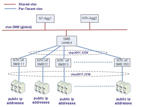
Tenants 11 to 250 are public address tenants.
Below are examples of the SMB configuration for SMB tenant 11 and tenant 12.
interface Port-channel1.2000
nameif outside
security-level 0
ip address 100.200.1.61 255.255.255.0 standby 100.200.1.62
interface Port-channel1.3011
nameif smb11
security-level 100
ip address 10.9.11.61 255.255.255.0 standby 10.9.11.62
!
interface Port-channel1.3012
nameif smb12
security-level 100
ip address 10.9.12.61 255.255.255.0 standby 10.9.12.62
route smb11 100.201.11.0 255.255.255.0 10.9.11.1 1
route smb12 100.201.12.0 255.255.255.0 10.9.12.1 1
Below are useful commands.
show route
show conn
show interface
show interface ip brief
Private Address Tenants
Refer to Figure 5-8 for the topology of private address tenants.
Tenants 1 to 10 shown in the diagram are private address tenants. In the Nexus 7000, tenant VRF instances are created to separate the tenants. The IP addresses for tenant VMs can be reused in different tenants - allows for overlapping IP addresses for tenant VM subnets for different tenants. The connected interface on the ASA itself however has to be uniquely addressed, and is in private space as well as no need to be able to route to it.
Figure 5-8 Private Address Tenants
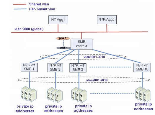
The servers of these tenants have private IP addresses in the DC and have public IP addresses (mapped IP addresses) in the ASA SMB context. For these servers, NAT and static routes are needed for access to these servers from the Internet as well as these servers initiating traffic to the Internet. The server IP addresses can be overlapped for different tenants, but it is not recommended.
From the ASA View
For the north to south traffic, static NAT is used to direct the traffic to the egress interface. Static routes are used to find the next hop. The next hop to the real server is the HSRP address of the individual Nexus 7000 tenant. The return traffic will be NAT'd to the public IP address in the SMB context and points to the HSRP address of the Nexus 7000 VLAN 2000 (global routing table) as the next hop.
For the traffic initiated by the servers (other than the configured static NAT servers) in the DC, the per-tenant dynamic pool in the ASA SMB context is used for NAT. The next hop is the HSRP address of the Nexus 7000 VLAN 2000. For the returned traffic, NAT will decide the egress interface, and static routes are used to find the next hop.
From the Nexus 7000 Global Routing View
For the north to south traffic, the next hop is the shared ASA context outside interface. For the south to north traffic, the Nexus 7000 will use its routing table to route the traffic to the PE routers.
From the Nexus 7000 Per-Tenant VRF View
For the north to south traffic, the next hop is the server. For the south to north traffic, the next hop is the shared ASA context per-tenant-inside interface.
See NAT Setup for detailed NAT setup information.
NAT Setup
This section presents the following topics:
Static NAT
Static NAT creates a fixed translation of a real address to a mapped address. Because the mapped address is the same for each consecutive connection, static NAT allows bidirectional connection initiation, both to and from the server (Figure 5-9).
Figure 5-9 Static NAT
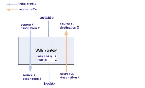
Refer to Information About Static NAT with Port Address Translation for detailed information about static NAT.
In this solution, static NAT is used for access to the private IP address servers from the Internet. For tenant 1, the related configuration on the ASA is shown below.
interface Port-channel1.2000
nameif outside
security-level 0
ip address 100.200.1.61 255.255.255.0 standby 100.200.1.62
!
interface Port-channel1.3001
nameif smb1
security-level 100
ip address 10.9.1.61 255.255.255.0 standby 10.9.1.62
object network smb-1-server1
host 11.4.1.11
object network smb-1-server2
host 11.4.1.12
object network smb-1-server3
host 11.4.1.13
object network smb-1-server21
host 11.4.1.21
object network smb-1-server22
host 11.4.1.22
object network smb-1-server23
host 11.4.1.23
object network smb-1-server24
host 11.4.1.24
object network smb-1-server25
host 11.4.1.25
object network smb-1-server26
host 11.4.1.26
object network smb-1-server27
host 11.4.1.27
object network smb-1-server28
host 11.4.1.28
object network smb-1-server29
host 11.4.1.29
object network smb-1-server30
host 11.4.1.30
object network smb-1-server1
nat (smb1,outside) static 100.201.1.11
object network smb-1-server2
nat (smb1,outside) static 100.201.1.12
object network smb-1-server3
nat (smb1,outside) static 100.201.1.13
object network smb-1-server21
nat (smb1,outside) static 100.201.1.21
object network smb-1-server22
nat (smb1,outside) static 100.201.1.22
object network smb-1-server23
nat (smb1,outside) static 100.201.1.23
object network smb-1-server24
nat (smb1,outside) static 100.201.1.24
object network smb-1-server25
nat (smb1,outside) static 100.201.1.25
object network smb-1-server26
nat (smb1,outside) static 100.201.1.26
object network smb-1-server27
nat (smb1,outside) static 100.201.1.27
object network smb-1-server28
nat (smb1,outside) static 100.201.1.28
object network smb-1-server29
nat (smb1,outside) static 100.201.1.29
object network smb-1-server30
nat (smb1,outside) static 100.201.1.30
route outside 0.0.0.0 0.0.0.0 100.200.1.1 1
route smb1 11.4.1.0 255.255.255.0 10.9.1.1 1
Below are useful commands.
show xlate
show route
show conn
Dynamic NAT
Dynamic NAT translates a group of real addresses to a pool of mapped addresses that are routable on the destination network. The translation is created only when the real host initiates the connection (Figure 5-10).
Figure 5-10 Dynamic NAT
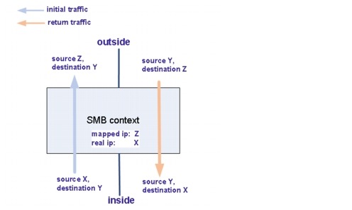
Refer to Dynamic NAT for a detailed dynamic NAT explanation and configuration guide.
In this solution, dynamic NAT is used for the traffic initiated from the servers (other than the servers already configured as static NAT) in the DC.
Below is the configuration for the tenant SMB1.
interface Port-channel1.2000
nameif outside
security-level 0
ip address 100.200.1.61 255.255.255.0 standby 100.200.1.62
!
interface Port-channel1.3001
nameif smb1
security-level 100
ip address 10.9.1.61 255.255.255.0 standby 10.9.1.62
object network smb1-mapped
range 100.201.1.1 100.201.1.10
object network smb1-real
subnet 11.4.1.0 255.255.255.0
object network smb1-real
nat (smb1,outside) dynamic smb1-mapped
Below are useful commands.
show xlate
show route
show conn
Interconnecting Tenants
By default, interfaces on the same security level cannot communicate with each other. To enable the communication between the same security level, the same-security-traffic permit inter-interface command must be configured. With the same-security-traffic permit inter-inerface command enabled, complicated ACLs are placed between tenants for the security. In this implementation, tenants are not allowed to talk to each other inside the ASA, and the same-security-traffic permit inter-interface command is disabled.
In this implementation, we have private IP address servers and public IP address servers, and we want to block the inter-tenants communications to the public IP addresses servers.
Table 5-3 shows if the inter-tenants communications is possible in this implementation.
|
|
|
|
Initiated from Public |
No |
Yes |
Initiated from Private |
No |
Yes |
In general, if the packet is initiated by private or public, but the destination is a public IP address server, the inter-tenant communication will fail. If the packet is initiated by private or public, but the destination is a private IP address server, the inter-tenant communication will succeed. For those inter-tenants, communication is possible. The inter-tenants' traffic is sent to the Nexus 7000 by the ASA, and the Nexus 7000 sends the traffic back to the ASA. We do not recommend inter-tenants communications due to the security considerations and recommend using public IP addresses in all Copper tenants.
These scenarios are discussed in detail below.
For Scenario 1, Public to Public (Fail)
When the packet reaches the ASA from the public IP address server, the ASA will use the routing table to find the egress interface, and the ASA will find the destination SMB tenant interface as the egress interface. As same-security-traffic permit inter-interface is disabled, the packet will be dropped.
For Scenario 2, Public to Private (Pass)
The destination of this kind of traffic is a mapped public IP address. When the ASA receives the packet, it will use the routing table to find the egress interface. There is no entry in the routing table for the mapped IP address, and the ASA will use the default route to send this traffic to the Nexus 7000 HSRP address. The Nexus 7000 routers have a static route for this subnet and point to the ASA outside interface as the next hop. When the ASA receives the packet from the outside interface, it will use static NAT to find the egress interface and the routing table to find the next hop. The return traffic will use NAT to direct the traffic to the outside interface of the ASA. After reaching the Nexus 7000, the
Nexus 7000 will send the packet back to the ASA, and the ASA will use the routing table to find the egress interface and the next hop.
For Scenario 3, Private to Public (Fail)
As the destination is a public IP address server, the ASA will use static routes to find the egress, and the egress interface is the SMB tenant inside interface. Since same-security-traffic permit inter-interface is disabled, the packet will be dropped.
For Scenario 4, Private to Private (Pass)
If the traffic is initiated by the private IP address servers, (does not matter if it is configured as the static NAT server or other servers), when the packet reaches the ASA, the ASA will look up the routing table, as the destination is a mapped address. The ASA will use the default routes to direct the traffic to the egress interface. The packet will go to the Nexus 7000 and come back as Nexus 7000 routers have static routes pointing to the ASA outside interface as the next hop. When the ASA receives the packet, it will use static NAT to NAT and direct the packet to the egress interface, which is the SMB tenant inside interface. The return traffic will be static NAT'd and directed to the outside interface of the ASA. The traffic will go to the Nexus 7000 and then return. The ASA will use NAT to NAT and direct the packet to the egress interface of the SMB tenant.
ASA VPN Configuration
The ASA 5555-X appliance is used to provide VPN services to the Gold tenants. This appliance is a 4 Gbps firewall device capable of up to 1 Gbps of VPN throughput. Up to 5000 VPN peers can be configured on this appliance. In this implementation, a mix of IPsec and SSL VPN tunnels are established on this appliance.
This section presents the following topics:
ASA VPN Redundancy
The ASA 5555-X providing VPN services and acting as the VPN gateway must be configured in single-context mode and can only be configured in active/standby redundancy mode. In active/standby redundancy mode, only the active ASA is responsible for all VPN gateway functionality. The active ASA terminates all established SSL VPN and IPsec remote access VPN tunnels and maps the client traffic to the appropriate outbound VLANs. Since the active ASA responds to traffic directed to the active IP address, all traffic is directed to the active ASA. All established tunnels in the VPN session database are replicated from the active ASA to the standby ASA. This ensures that the standby ASA can take over the responsibility of the active, should it fail. All state information is sent through the stateful link (Figure 5-11).
Figure 5-11 ASA VPN Redundancy
As with the other ASA used to provide security services to the Gold tenant, the ASA 5555-x are port-channels that are connected to the vPC on a pair of aggregation Nexus 7000 switches.
ASA VPN Multitenancy
The ASA 5555-X providing VPN services for the Gold service class runs in single-context mode. The ASA configured in multiple-context mode cannot be used to provide VPN services. Due to this limitation, the virtualization capability of the ASA cannot be used to differentiate between Gold tenants in this DC environment. To differentiate between these tenants, two VPN configuration options are used in the ASA. These options are group-policy VLAN ID and tunnel-group configuration.
Group-policy VLAN ID
The group policy is a set of attributes that define how users use a connection through a tunnel after tunnel establishment. The group-policy VLAN ID determines which outbound VLAN the decrypted traffic should be placed on. For every tenant, since all clear text traffic is sent to the DMZ vFW, the VLAN group must correspond to the VPN-outside interface of the tenant DMZ vFW.
Tunnel Group
A tunnel group consists of a set of records that determines tunnel connection policies. These records identify the servers to which the tunnel user is authenticated, as well as the accounting servers, if any, to which connection information is sent. They also identify a default group policy for the connection, and they contain protocol-specific connection parameters. Tunnel groups include a small number of attributes that pertain to creating the tunnel itself. Tunnel groups include a pointer to a group policy that defines user-oriented attributes.
ASA IPsec VPN Configuration
IPsec VPN services are provided using IPsec framework, which comprises a suite of protocols that provide confidentiality, authentication, integrity, and advanced security services. Confidentiality is provided using cryptographic algorithms and ciphers. Authentication is provided using hashing algorithms that generate message authentication codes. IPsec uses the following protocols to perform various functions:
•![]() Authentication Headers (AH) provide integrity, authentication, and protection against reply attacks.
Authentication Headers (AH) provide integrity, authentication, and protection against reply attacks.
•![]() Encapsulating Standard Protocol (ESP) provides confidentiality, authentication, integrity, and anti-replay.
Encapsulating Standard Protocol (ESP) provides confidentiality, authentication, integrity, and anti-replay.
•![]() Security Association (SA) provides the bundle of algorithms and parameters (such as keys) that are used to encrypt and authenticate a particular flow in one direction
Security Association (SA) provides the bundle of algorithms and parameters (such as keys) that are used to encrypt and authenticate a particular flow in one direction
•![]() Internet Security Association and Key Management Protocol (ISAKMP) is the negotiation protocol that lets two hosts agree on how to build an IPsec SA. A sample IPsec VPN configuration is shown below.
Internet Security Association and Key Management Protocol (ISAKMP) is the negotiation protocol that lets two hosts agree on how to build an IPsec SA. A sample IPsec VPN configuration is shown below.
Cisco ASA platform has a rich set of features used for secure access. More details can be found about new features released in latest release at this link:Cisco ASA Series , Release Notes , 9.0(x).
Sample IPsec VPN Configuration
dc02-asa5555-1# sh run crypto
crypto ipsec ikev1 transform-set ipsec-tz esp-3des esp-md5-hmac
crypto ipsec security-association pmtu-aging infinite
crypto dynamic-map ipsec-cm 1 set ikev1 transform-set ipsec-tz
crypto dynamic-map ipsec-cm 1 set security-association lifetime seconds 7200
crypto map ipsec-cm 1 ipsec-isakmp dynamic ipsec-cm
crypto map ipsec-cm interface internet
crypto ca trustpool policy
crypto ikev1 enable internet
crypto ikev1 policy 1
authentication pre-share
encryption 3des
hash md5
group 2
lifetime 3600
dc02-asa5555-1# sh run tunnel-group customer_gold1-ipsec
tunnel-group customer_gold1-ipsec type remote-access
tunnel-group customer_gold1-ipsec general-attributes
address-pool customer_gold1
authentication-server-group (internet) LOCAL
authorization-server-group (internet) LOCAL
tunnel-group customer_gold1-ipsec ipsec-attributes
ikev1 pre-shared-key *****
dc02-asa5555-1# sh run group-policy customer_gold1-ipsec
group-policy customer_gold1-ipsec internal
group-policy customer_gold1-ipsec attributes
vpn-simultaneous-logins 200
vpn-tunnel-protocol ikev1
group-lock value customer_gold1-ipsec
split-tunnel-policy tunnelspecified
split-tunnel-network-list value customer_gold1
vlan 1701
ASA SSL VPN Configuration
The ASA 5555-X provides two types of SSL VPN tunnels, with the major difference between the two being what the client uses to establish these tunnels. The ASA provide clientless SSL VPN/WebVPN tunnel services, which enable users to use their supported web browser to set up and establish SSL/ TLS tunnels to the ASA endpoint. Typically, these users gain access to web resources. The ASA also provides AnyConnect SSL VPN tunnels, which enable clients to gain access to full network resources. These clients establish SSL or IPsec tunnels to the ASA using the Cisco AnyConnect Secure Mobility client. In both cases, users are required to authenticate to the respective tunnel groups. If this authentication is successful for the clientless SSL VPN user, that user will be presented with the
Cisco Secure Desktop (CSD) portal. If an AnyConnect user authenticates using a web browser, the AnyConnect Secure Mobility Client installer is pushed from the ASA that matches the user's OS. The AnyConnect SSL VPN tunnel is successfully established if users authenticate with a current version of the AnyConnect Client on the ASA. A sample configuration required to set up SSL VPN tunnels is shown below.
Sample ASA SSL VPN Configuration
dc02-asa5555-1# sh run webvpn
webvpn
enable internet
no anyconnect-essentials
csd image disk0:/csd_3.6.6210-k9.pkg
anyconnect image disk0:/anyconnect-win-3.1.01065-k9.pkg 1
anyconnect profiles anyconnect-profile disk0:/RDP.xml
anyconnect enable
tunnel-group-preference group-url
dc02-asa5555-1#
dc02-asa5555-1#
dc02-asa5555-1# sh run tunnel-group customer_gold1-ssl
tunnel-group customer_gold1-ssl type remote-access
tunnel-group customer_gold1-ssl general-attributes
address-pool customer_gold1
authentication-server-group (internet) LOCAL
authorization-server-group (internet) LOCAL
tunnel-group customer_gold1-ssl webvpn-attributes
group-url https://100.200.1.51/customer_gold1 enable
dc02-asa5555-1#
dc02-asa5555-1# sh run group-policy customer_gold1-ssl
group-policy customer_gold1-ssl internal
group-policy customer_gold1-ssl attributes
vpn-simultaneous-logins 200
vpn-tunnel-protocol ssl-client ssl-clientless
group-lock value customer_gold1-ssl
split-tunnel-policy tunnelspecified
split-tunnel-network-list value customer_gold1
vlan 1701
webvpn
anyconnect profiles value anyconnect-profile type user
dc02-asa5555-1#
dc02-asa5555-1# sh run user ssl1
username ssl1 password JSKNK4oromgGd3D9 encrypted
username ssl1 attributes
vpn-group-policy customer_gold1-ssl
Compute Firewall
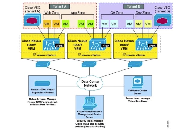
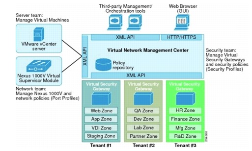
In this implementation, the VSG acts as the compute firewall. The VSG is a virtual firewall appliance that provides trusted access to virtual DC and cloud environments with dynamic policy-driven operation, mobility-transparent enforcement, and scale-out deployment for dense multitenancy. The VSG operates with the Nexus 1000V DVS in the VMware vSphere hypervisor. The VSG leverages the virtual network service data path (vPath) that is embedded in the Nexus 1000V VEM. Figure 5-12 shows a typical VSG deployment topology.
Figure 5-12 VSG Deployment Topology
This section presents the following topics:
VSG Deployment
This section presents the following topics:
•![]() Virtual Network Management Center
Virtual Network Management Center
ESXi Service Cluster
The VSG virtual appliances are hosted on ESXi hosts. For this implementation, the VSG appliances are hosted on a cluster of ESXi hosts dedicated for hosting virtual services appliances. Table 5-4 shows the vSphere cluster, ESXi hosts, and blade server assignment for ESXi hosts dedicated for hosting VSG virtual appliances.
The VSG comes with High Availability (HA). It is not recommended to use the vSphere HA feature, FT feature, or vSphere Distributed Resource Scheduling (DRS) feature for the VSG. For this implementation, vSphere HA is disabled, and vSphere DRS is set to partially automated for initial virtual appliance power on placement only.
For this implementation, each VSG is an HA-pair of primary and secondary nodes. For HA, the primary and secondary nodes of each VSG should not be hosted on the same ESXi host. vSphere DRS groups are configured for this purpose. Figure 5-13 shows the vSphere DRS groups' configuration.
Figure 5-13 vSphere DRS Groups and Rules for VSG Virtual Appliances
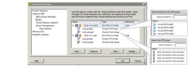
Two host DRS groups are configured, with each host group containing half of the ESXi hosts in the cluster. Two VMs' DRS groups are also configured; for each VSG HA-pair, the primary node is placed in one VMs, group, while the secondary node is placed in the other group. Each VMs, group is configured to include both primary and secondary nodes (from different VSG HA-pair) to ensure even load on the ESXi hosts.
Four SAN data stores are made available for hosting the VSG virtual appliances, and all ESXi hosts in the cluster have access to all four data stores. The primary and secondary nodes of each VSG should not be placed on the same data store.
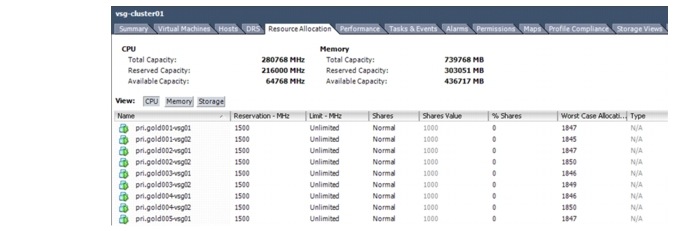
Each VSG node (be it the active or standby node of the VSG HA-pair) reserves CPU and memory resources on the ESXi host. On vSphere, a reservation specifies the guaranteed minimum allocation of resources for a VM. The ESXi host performs reservation admission control. If a VM has a reservation defined, the ESXi host must have at least that much resource unreserved (not just unused, but unreserved), or else it will refuse to power on the VM. The ESXi host guarantees the availability of the reserved resources even when the physical server is heavily loaded.

Note ![]() As of VSG version 4.2(1)VSG1(4.1), the resources reservation of each VSG node is as follows:
As of VSG version 4.2(1)VSG1(4.1), the resources reservation of each VSG node is as follows:
•![]() CPU - 1500 MHz per vCPU
CPU - 1500 MHz per vCPU
•![]() Memory - 2048 MB
Memory - 2048 MB
Resources reservation placed a limit on the number of powered on VSG nodes that each ESXi host can support. The number of ESXi hosts required for hosting VSG appliances depends on the following:
•![]() CPU (number of CPU, number of cores per CPU) and memory (amount of DRAM installed) of the ESXi hosts
CPU (number of CPU, number of cores per CPU) and memory (amount of DRAM installed) of the ESXi hosts
•![]() Number of VSG appliances deployed
Number of VSG appliances deployed
Figure 5-14 shows the resource allocation of the vsg-cluster01 cluster. This figure shows the total, reserved, and available capacities of CPU and memory for all ESXi hosts in the cluster.
Figure 5-14 vSphere Resource Allocation of a Cluster
Virtual Network Management Center
The Cisco Virtual Network Management Center (VNMC) virtual appliance is a custom VM based on Red Hat Enterprise Linux (RHEL). The VNMC provides centralized device and security policy management of the VSG for the Nexus 1000V Series switch. The VNMC manages the VSG appliances that are deployed throughout the DC from a centralized location. For this implementation, the VNMC virtual appliance is deployed on a management vSphere cluster that is not part of the
tenants' compute infrastructure. VNMC does not provide its own HA capability, relying on vSphere HA instead. For proper operations, the VNMC must have management access to vSphere vCenter, Nexus 1000V VSM, and all VSG appliances under its administration. The VNMC registers to vSphere vCenter as a plug-in, and the VSM and VSG appliances register to VNMC via the policy agent. Figure 5-15 shows the VNMC components.
Figure 5-15 VNMC Components
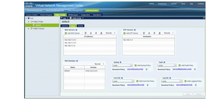
The device specific settings for the VNMC virtual appliance are configured via the VNMC Profile. Figure 5-16 shows a typical VNMC Profile. The following settings are configurable:
•![]() Time zone
Time zone
•![]() DNS Servers
DNS Servers
•![]() DNS Domain Name
DNS Domain Name
•![]() NTP Servers—The clock on both VNMC and VSG appliances must be in-sync.
NTP Servers—The clock on both VNMC and VSG appliances must be in-sync.
•![]() Syslog Server
Syslog Server
•![]() Core File Policy—TFTP server for VNMC to upload any process core file for later analysis.
Core File Policy—TFTP server for VNMC to upload any process core file for later analysis.
•![]() Fault Policy—Determine if and for how long cleared faults on the VNMC should be kept.
Fault Policy—Determine if and for how long cleared faults on the VNMC should be kept.
•![]() Logging Policy—Logging settings for logging to the local log file on the VNMC.
Logging Policy—Logging settings for logging to the local log file on the VNMC.
Figure 5-16 VNMC Profile
Virtual Security Gateway
The VSG virtual appliance is a VM based on NX-OS. The VSG is a virtual firewall appliance that provides trusted access to virtual DC and cloud environments with dynamic policy-driven operation, mobility-transparent enforcement, and scale-out deployment for dense multitenancy.
For this implementation, the VSG virtual appliances are deployed on the same vSphere and Nexus 1000V infrastructure as the protected VMs. A dedicated set of ESXi hosts in a cluster are used to host the VSG virtual appliances.
Each VSG has three network interfaces:
•![]() Data/Service interface (1st vNIC)
Data/Service interface (1st vNIC)
•![]() Management interface (2nd vNIC)
Management interface (2nd vNIC)
•![]() HA interface (3rd vNIC)
HA interface (3rd vNIC)
The Data/Service and HA interfaces require their own dedicated VLANs and port profiles. The Management interface can use the existing management VLAN and port profile, however, for this implementation, a dedicated VSG management VLAN and port profile is used.
VSG appliances for each tenant can be provisioned with one VLAN for Data/Service interfaces (for all the VSG appliances of the tenants) and one VLAN for HA interfaces (for all the VSG appliances of the tenants), however, in a deployment with many tenants, such a deployment option would use up many VLAN resources. For this implementation, one shared Data/Service VLAN and one shared HA VLAN are used for all VSG appliances for all tenants. Table 5-5 shows the configuration for the interfaces.
Note ![]() 1. Licenses for VSG appliances are based on the number of CPUs (regardless of the number of cores on the CPU) of the ESXi hosts hosting the appliances. Each VSG virtual appliance has three vNICs. In an HA setup with a VGS HA-pair, the pair would consume six vNICs.
1. Licenses for VSG appliances are based on the number of CPUs (regardless of the number of cores on the CPU) of the ESXi hosts hosting the appliances. Each VSG virtual appliance has three vNICs. In an HA setup with a VGS HA-pair, the pair would consume six vNICs.
2. In large scale implementation with a larger number of VGS appliances, the VSG will consume a large number of vEth interfaces on the Nexus 1000V. In such deployments, it would be better to deploy a separate Nexus 1000V dedicated for the VSG virtual appliances. Deploying an additional Nexus 1000V should not require more licenses than when VSG appliances shared the same Nexus 1000V of the tenants' VMs.
Figure 5-17 VSG Network Topology
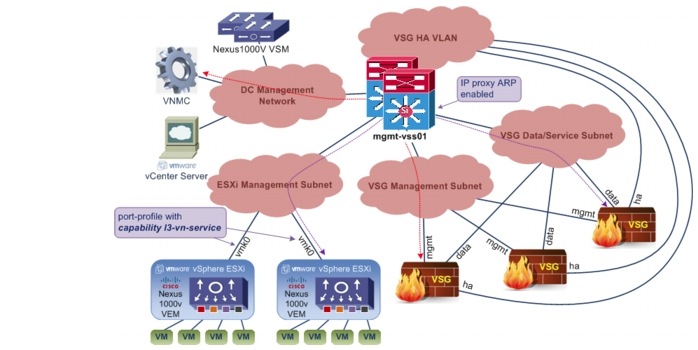
Figure 5-17 shows the network topology for the VSG deployment for this implementation. The VSG appliances are configured to communicate with the vPaths/VEMs in L3 mode. Each vPath/VEM uses the vmk0 interface to communicate with the VGS appliances, via the IP network. The Nexus 1000V port profile that the vmk0 interfaces attach to must be configured with capability l3-vn-service.
VSG uses the Management interface to communicate with VNMC, and it uses the Data/Service interface to communicate with the vPath/VEM. On the router interface facing the VSG appliances Data/Service interfaces, IP-proxy Address Resolution Protocol (ARP) must be enabled in order for the VSG appliances to be able to ARP for the IP addresses of the vmk0 interfaces of ESXi hosts.
Organization Structure
The VNMC provides the ability to support multitenant environments. A multitenant environment enables the division of large physical infrastructures into logical entities/organizations. Multitenancy allows logical isolation between organizations without providing a dedicated physical infrastructure for each organization. The VNMC administrator can assign unique resources to each tenant through the related organization in the multitenant environment. VNMC provides a strict organizational hierarchy as follows:
1. ![]() Root
Root
2. ![]() Tenant
Tenant
3. ![]() Virtual Data Center
Virtual Data Center
4. ![]() Application
Application
5. ![]() Tier
Tier
VMDC Tenants' Organization Structure
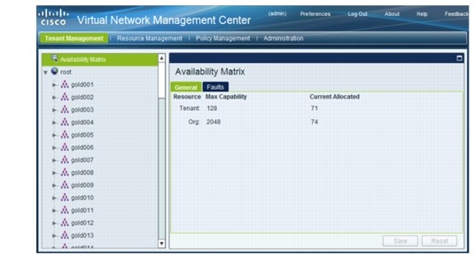
For each VMDC tenant, a flat, one-level organizational hierarchy is created for the tenant under the Root organization, and VSG compute firewalls are assigned at the tenant org level. Figure 5-18 shows the tenants created for this implementation.
Figure 5-18 VMDC Tenants
Note ![]() Compute firewall(s) should be added at the tenant level or below, and not at the Root org level.
Compute firewall(s) should be added at the tenant level or below, and not at the Root org level.
Management Organization Structure
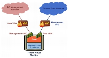
For this implementation, each protected VM has two vNICs, the data vNIC for the tenant data traffic and the management vNIC for back-end management traffic of the VMs. The data vNIC of each tenant VM would be protected by the dedicated VSG assigned to the tenant, while the management vNIC of all tenants' VMs are organized into one vm-mgmt tenant with its own VSG resources. Figure 5-19 illustrates the VSG appliances' deployment for a typical tenant VM.
Figure 5-19 Tenant Virtual Machine and VSG Appliances
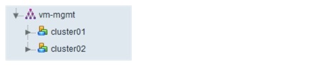
The vm-mgmt tenant is organized into two virtual DCs organizational hierarchy. The organizational hierarchy is along the vSphere cluster, and each sub-org is assigned with one VSG to protect the management vNIC of the VMs in that cluster. Figure 5-20 shows the vm-mgmt organizational hierarchy.
Figure 5-20 Management Tenant
Security Policies
This section presents the following topics:
Tenants Security Policies
This section presents the following topics:
Expanded Gold Tenant
Each VMDC Expanded Gold tenant is provisioned with two security zones, a Private (PVT) zone and a DMZ. The Gold tenant PVT zone is allotted with three VLANs, and the related three Nexus 1000V port profiles, allowing the Gold tenant to construct a three-tier application architecture (presentation/ web tier, logic/application tier, data/database tier) with three IP subnets on the PVT zone. The Gold tenant DMZ is allotted with only one VLAN and one related Nexus 1000V port profile. All VMs for the Gold tenant DMZ belong to one IP subnet. Each Gold tenant is assigned with two VSG appliances, one for the PVT zone and DMZ respectively. Three security profiles are configured for the Gold tenant PVT zone, one for each of the three Nexus 1000V port profiles. The Gold tenant DMZ has one security profile for its single Nexus 1000V port profile. Figure 5-21 shows the security profiles, VSG appliances' assignment, and the related Nexus 1000V configuration for one of the Gold tenants.
Figure 5-21 Expanded Gold Tenant Security Profiles
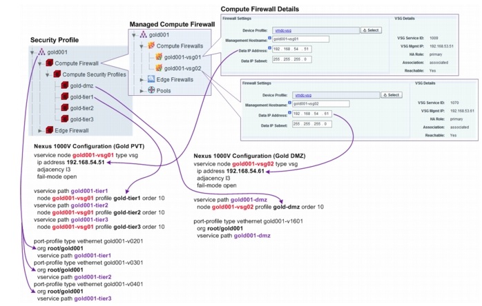
Note ![]() For the test implementation, the VMs deployed are not provisioned with any actual applications set forth in the three-tier application architecture. Instead, each VM is provisioned with HTTP, FTP, and TFTP servers, which are used to approximate the three-tier data traffic flows.
For the test implementation, the VMs deployed are not provisioned with any actual applications set forth in the three-tier application architecture. Instead, each VM is provisioned with HTTP, FTP, and TFTP servers, which are used to approximate the three-tier data traffic flows.
For the three-tier policies using three VLANs, FTP/TFTP policies are not tested. The VSG FTP/ TFTP protocol inspect on the VSG fails to open the pinhole required for the data connection when the source and destination vNICs are under the same VSG protection, but on different VLANs. See CSCud39323 for more details.
This section presents the following topics:
Private Zone
Gold Tier 1 (Presentation/Web Tier) Security Policies
Table 5-6 lists the security policies configuration for the gold-tier1 security profile.
Gold Tier 2 (Logic/Application Tier) Security Policies
Table 5-7 lists the security policies configuration for the gold-tier2 security profile.
Gold Tier 3 (Data/Database Tier) Security Policies
Table 5-8 lists the security policies configuration for the gold-tier3 security profile.
Note ![]() 1. All conditions are and conditions, unless specified otherwise.
1. All conditions are and conditions, unless specified otherwise.
2. For each tier, a server load balancer is deployed. The server load balancer load balances traffic to the VM. Clients do not see the real IP addresses of the VMs, they only see the virtual IP addresses.
3. The server load balancer NATs the source IP address of load-balanced traffic going to the VMs to IP addresses in the SLB SNAT pool. Each tier has its own SNAT pool.
4. SLB Probe, Tier 1 VMs, Tier 1 VIP addresses, Tier 2 SLB SNAT Pool, etc, are conditions configured as a VNMC object group. The conditions in the object group have or semantics.
Demilitarized Zone
Table 5-9 lists the security policies configuration for the gold-dmz security profile.
Note ![]() 1. All conditions are AND conditions, unless specified otherwise.
1. All conditions are AND conditions, unless specified otherwise.
2. A server load balancer is deployed for the DMZ VMs. The server load balancer load balances traffic to the VM. Clients do not see the real IP addresses of the VMs, they only see the virtual IP addresses.
3. The server load balancer NATs the source IP address of load-balanced traffic going to the VMs to IP addresses in the SLB SNAT pool. Each tier has its own SNAT pool.
4. SLB Probe, DMZ VMs, etc, are conditions configured as a VNMC object group. The conditions in the object group have OR semantics.
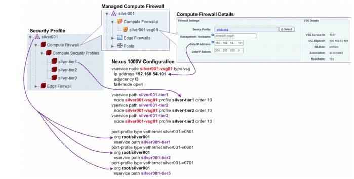
Each VMDC Silver tenant is allotted with three VLANs, and the related three Nexus 1000V port profiles, allowing the Silver tenant to construct a three-tier application architecture (presentation/web tier, logic/application tier, data/database tier) with three IP subnets. Each Silver tenant is assigned with one VSG. Three security profiles are configured for the Silver tenant, one for each of the three Nexus 1000V port profiles. Figure 5-22 shows the security profiles, VSG assignment, and the related Nexus 1000V configuration for one of the Silver tenants.
Figure 5-22 Silver Tenant Security Profiles
1. ![]() For the test implementation, the VMs deployed are not provisioned with any actual applications set forth in the three-tier application architecture. Instead, each VM is provisioned with HTTP, FTP, and TFTP servers, which are used to approximate the three-tier data traffic flows.
For the test implementation, the VMs deployed are not provisioned with any actual applications set forth in the three-tier application architecture. Instead, each VM is provisioned with HTTP, FTP, and TFTP servers, which are used to approximate the three-tier data traffic flows.
2. ![]() For the three-tier policies using three VLANs, FTP/TFTP policies are not tested. The VSG FTP/ TFTP protocol inspect on the VSG fails to open the pinhole required for data connection when the source and destination vNICs are under the same VSG protection, but on different VLANs. See CSCud39323 for more details.
For the three-tier policies using three VLANs, FTP/TFTP policies are not tested. The VSG FTP/ TFTP protocol inspect on the VSG fails to open the pinhole required for data connection when the source and destination vNICs are under the same VSG protection, but on different VLANs. See CSCud39323 for more details.
Silver Tier 1 (Presentation/Web Tier) Security Policies
Table 5-10 lists the security policies configuration for the silver-tier1 security profile.
Silver Tier 2 (Logic/Application Tier) Security Policies
Table 5-11 lists the security policies configuration for the silver-tier2 security profile.
Silver Tier 3 (Data/Database Tier) Security Policies
Table 5-12 lists the security policies configuration for the silver-tier3 security profile.
1. ![]() All conditions are and conditions, unless specified otherwise.
All conditions are and conditions, unless specified otherwise.
2. ![]() For each tier, a server load balancer is deployed. The server load balancer load balances traffic to the VM. Clients do not see the real IP addresses of the VMs, they only see the virtual IP addresses.
For each tier, a server load balancer is deployed. The server load balancer load balances traffic to the VM. Clients do not see the real IP addresses of the VMs, they only see the virtual IP addresses.
3. ![]() The server load balancer NATs the source IP address of load-balanced traffic going to the VMs to IP addresses in the SLB SNAT pool. Each tier has its own SNAT pool.
The server load balancer NATs the source IP address of load-balanced traffic going to the VMs to IP addresses in the SLB SNAT pool. Each tier has its own SNAT pool.
4. ![]() SLB Probe, Tier 1 VMs, Tier 1 VIP addresses, Tier 2 SLB SNAT Pool, etc, are conditions configured as a VNMC object group. The conditions in the object group have or semantics.
SLB Probe, Tier 1 VMs, Tier 1 VIP addresses, Tier 2 SLB SNAT Pool, etc, are conditions configured as a VNMC object group. The conditions in the object group have or semantics.
Bronze Tenant
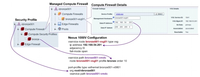
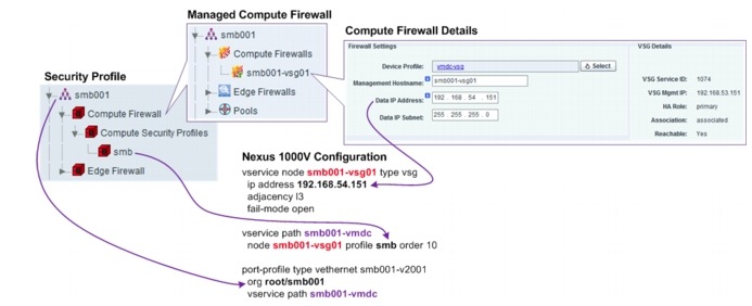
Each VMDC Bronze tenant is allotted with one VLAN and one related Nexus 1000V port profile. All VMs for the Bronze tenant belong to one IP subnet. Each Bronze tenant is assigned with one VSG. One security profile is configured for the Bronze tenant, with one Nexus 1000V port profile. Figure 5-23 shows the security profiles, VSG assignment, and the related Nexus 1000V configuration for one of the Bronze tenants.
Figure 5-23 Bronze Tenant Security Profile
Note ![]() Note For the test implementation, the VMs deployed are not provisioned with any actual applications set forth in the three-tier application architecture. Instead, each VM is provisioned with HTTP, FTP, and TFTP servers, which are used to approximate the three-tier data traffic flows.
Note For the test implementation, the VMs deployed are not provisioned with any actual applications set forth in the three-tier application architecture. Instead, each VM is provisioned with HTTP, FTP, and TFTP servers, which are used to approximate the three-tier data traffic flows.
Bronze Flat Security Policies
Table 5-13 shows the security policies for one of the Bronze tenants; other Bronze tenants have similar settings.
Bronze Three-tier Security Policies
Table 5-14 show that each Bronze tenant is only assigned one VLAN and one Nexus 1000V port profile, and thus, only one security profile is assigned. With vZone and object groups, the VNMC provides the flexibility to configure three-tier separation using only one VLAN (one IP subnet, one security profile, one port profile).
Note ![]() 1. It is possible/supported to bind one security profile to multiple port profiles, but one port profile can only bind to one security profile at a time.
1. It is possible/supported to bind one security profile to multiple port profiles, but one port profile can only bind to one security profile at a time.
2. All conditions are and conditions, unless specified otherwise.
3. The Bronze VMs, Tier 1 VMs, etc, are conditions configured as a VNMC object group.
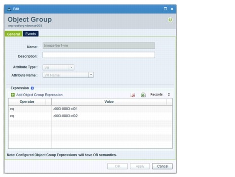
4. Tier 1 VM, Tier 2 VM, and Tier 3 VM are configured using object groups. The object-group filter expression matches against the VM name attribute. Figure 5-24 shows the object-group configuration for Tier 1 VM. The conditions in the object group have or semantics.
Figure 5-24 Object-group Configuration
Copper/SMB Tenant
Each VMDC Copper/SMB tenant is allotted with one VLAN and one related Nexus 1000V port profile. All VMs for the Copper/SMB tenant belong to one IP subnet. Each Copper/SMB tenant is assigned with one VSG. One security profile is configured for the Copper/SMB tenant, with one Nexus 1000V port profile. Figure 5-25 shows the security profiles, VSG assignment, and the related Nexus 1000V configuration for one of the Copper/SMB tenants.
Figure 5-25 Copper/SMB Tenant Security Profile
The security policies for the Copper/SMB tenant are similar to those of Bronze tenant. See the Bronze Tenant section for details.
Management Security Policies
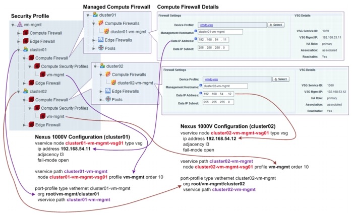
The vm-mgmt tenant consists of all of the back-end vNICs of all VMs of all tenants. The back-end vNICs are used for management of VMs by the Service Provider. The vm-mgmt tenant is sub-divided into two virtual DCs, one virtual DC for each cluster. Each cluster is allotted with one VLAN and one related Nexus 1000V port profile, and all vNICs for the cluster belong to one IP subnet (Table 5-15).
Each cluster is assigned with one VSG. One security profile is configured for each cluster, along with one Nexus 1000V port profile. Figure 5-26 shows the security profiles, VSG assignment, and the related Nexus 1000V configuration for one of the vm-mgmt tenants.
Figure 5-26 vm-mgmt Tenant Security Profile
Note ![]() 1. All conditions are and conditions, unless specified otherwise.
1. All conditions are and conditions, unless specified otherwise.
2. The IP address of the management vNIC is assigned via DHCP.
3. VM management vNIC, SNMP Managers, NFS Servers, etc. are conditions configured as a VNMC object group, using the IP subnet or IP address list as the filter expression. The conditions in the object group havee or semantics.
Services Best Practices and Caveats
ASA Firewall Appliance Best Practices
•![]() The ASA FT and stateful links should be dedicated interfaces between the primary and secondary ASA.
The ASA FT and stateful links should be dedicated interfaces between the primary and secondary ASA.
•![]() Failover interface policies should be configured to ensure that the security context fails over to the standby ASA if monitored interfaces are down.
Failover interface policies should be configured to ensure that the security context fails over to the standby ASA if monitored interfaces are down.
•![]() Configure an appropriate port-channel load-balancing scheme on the ASA to ensure that all port-channel interfaces are used to forward traffic out of the ASA.
Configure an appropriate port-channel load-balancing scheme on the ASA to ensure that all port-channel interfaces are used to forward traffic out of the ASA.
Copper Implementation Best Practices
•![]() Configure all Copper tenants' servers with either public or private IP addresses, not a mix of both types. If both types are needed, use seperate ASA context for all public addressed tenants and a separate context for all private addressed tenants.
Configure all Copper tenants' servers with either public or private IP addresses, not a mix of both types. If both types are needed, use seperate ASA context for all public addressed tenants and a separate context for all private addressed tenants.
•![]() Private IP addresses for servers can be overlapped for different tenants, and requires the use of NAT with separate public IP addresses per tenant for outside.
Private IP addresses for servers can be overlapped for different tenants, and requires the use of NAT with separate public IP addresses per tenant for outside.
Compute Firewall Best Practices
•![]() The VSG does not support vSphere HA and DRS. On clusters dedicated for hosting VSG virtual appliances, disable vSphere HA and DRS. On clusters hosting both VSG virtual appliances and other VMs, disable HA and DRS for the VSG virtual appliances.
The VSG does not support vSphere HA and DRS. On clusters dedicated for hosting VSG virtual appliances, disable vSphere HA and DRS. On clusters hosting both VSG virtual appliances and other VMs, disable HA and DRS for the VSG virtual appliances.
•![]() For a VSG HA-pair, the primary and secondary nodes should be hosted on the same ESXi host. Use vSphere anti-affinity rules or DRS groups to ensure this.
For a VSG HA-pair, the primary and secondary nodes should be hosted on the same ESXi host. Use vSphere anti-affinity rules or DRS groups to ensure this.
•![]() Each VSG virtual appliance (be it active or standby node) reserves CPU and memory resources from the ESXi host. Make sure the ESXi host has enough unreserved CPU and memory resources, otherwise, the VSG virtual appliance will not power on.
Each VSG virtual appliance (be it active or standby node) reserves CPU and memory resources from the ESXi host. Make sure the ESXi host has enough unreserved CPU and memory resources, otherwise, the VSG virtual appliance will not power on.
•![]() Make sure that the clocks on the VNMC, VSGs, and Nexus 1000V are synchronized. The VSGs and Nexus 1000V will not be able to register to the VNMC if the clocks are too out of sync.
Make sure that the clocks on the VNMC, VSGs, and Nexus 1000V are synchronized. The VSGs and Nexus 1000V will not be able to register to the VNMC if the clocks are too out of sync.
•![]() Enable IP proxy ARP on the router interface(s) on the subnet/VLAN facing the VSG data interfaces.
Enable IP proxy ARP on the router interface(s) on the subnet/VLAN facing the VSG data interfaces.
•![]() On the VNMC, compute firewalls should be added at the tenant level or below, and not at the Root org level.
On the VNMC, compute firewalls should be added at the tenant level or below, and not at the Root org level.
•![]() For the tenant, the DMZ should have its own VSG compute firewall, separate from the firewall used on the PVT zone.
For the tenant, the DMZ should have its own VSG compute firewall, separate from the firewall used on the PVT zone.
•![]() When configuring security policies/rules on the VNMC, the attributes used for filtering conditions should be preferred in the following order:
When configuring security policies/rules on the VNMC, the attributes used for filtering conditions should be preferred in the following order:
–![]() Network attributes, most prefer, providing highest performance for VSG - VM Attributes
Network attributes, most prefer, providing highest performance for VSG - VM Attributes
–![]() vZone, lest prefer, lowest VSG performance Compute Firewall Caveats
vZone, lest prefer, lowest VSG performance Compute Firewall Caveats
•![]() The VSG FTP/TFTP protocol inspect on the VSG fails to open the pinhole required for data connection when the source and destination vNICs are under the same VSG protection, but on different VLANs. See CSCud39323 for more details.
The VSG FTP/TFTP protocol inspect on the VSG fails to open the pinhole required for data connection when the source and destination vNICs are under the same VSG protection, but on different VLANs. See CSCud39323 for more details.
ACE 4710 Appliance Best Practices
•![]() The FT VLAN should be configured using the ft-port vlan <vlan-id> command to ensure that FT packets have the right QoS labels. This ensures that proper treatment is given to ACE FT packets in the network.
The FT VLAN should be configured using the ft-port vlan <vlan-id> command to ensure that FT packets have the right QoS labels. This ensures that proper treatment is given to ACE FT packets in the network.
•![]() Configure an appropriate port-channel load-balancing scheme to ensure that all port-channel interfaces are used to forward traffic out of the ACE appliance.
Configure an appropriate port-channel load-balancing scheme to ensure that all port-channel interfaces are used to forward traffic out of the ACE appliance.
•![]() To avoid MAC collision among operational ACE appliances on the same VLAN, use an appropriate shared-vlan host-id <1-16> to ensure that each ACE appliance has a unique MAC address on a shared VLAN.
To avoid MAC collision among operational ACE appliances on the same VLAN, use an appropriate shared-vlan host-id <1-16> to ensure that each ACE appliance has a unique MAC address on a shared VLAN.
 Feedback