VMDC 2.3 Implementation Guide
Bias-Free Language
The documentation set for this product strives to use bias-free language. For the purposes of this documentation set, bias-free is defined as language that does not imply discrimination based on age, disability, gender, racial identity, ethnic identity, sexual orientation, socioeconomic status, and intersectionality. Exceptions may be present in the documentation due to language that is hardcoded in the user interfaces of the product software, language used based on RFP documentation, or language that is used by a referenced third-party product. Learn more about how Cisco is using Inclusive Language.
- Updated:
- April 8, 2013
Chapter: Layer 2 Implementation
Layer 2 Implementation
In the Virtualized Multiservice Data Center (VMDC) 2.3 solution, the goal is to minimize the use of Spanning Tree Protocol (STP) convergence and loop detection by the use of Virtual Port Channel (vPC) technology on the Nexus 7000. While STP is still running for protection as a backup, the logical topology is without loops and mostly edge ports, and the only non-edge ports are the ones to the Integrated Compute and Storage (ICS) switches (Nexus 5000), which are connected with back-to-back vPC. This is explained in more detail in the Layer 2 at Nexus 7004 Aggregation section.
The Nexus 7000 based DC-Aggregation switches form the heart of the Layer 2 (L2) network design and implement the L2/Layer 3 (L3) boundary. All services appliances and ICS stacks attach to the Aggregation layer using vPCs. Integrated compute and storage includes a switching layer that aggregates compute attachments and connects to the DC Aggregation layer. In VMDC 2.3, the ICS layer includes the Nexus 5500 series switches. Within the Compute layer, this solution uses Unified Computing System (UCS) 6248 Fabric Interconnects (FIs) and B-series blades, and there is a virtualized switching layer implemented with the Nexus 1000V. These aspects are covered in detail in the Compute and Storage Implementation chapter.
The L2 implementation details are split into the following major topics:
• Layer 2 at Integrated Compute and Storage
•Layer 2 Implementation at ICS Nexus 5500
•Layer 2 at Nexus 7004 Aggregation
•Connecting Service Appliances to Aggregation
•Layer 2 Best Practices and Caveats
Layer 2 at Integrated Compute and Storage
This section presents the following topics:
•Nexus 1000V to Fabric Interconnect
•Fabric Interconnect to Nexus 5500
Nexus 1000V to Fabric Interconnect
The Nexus 1000V provides the virtualized switch for all of the tenant VMs. The Nexus 1000V is a virtualized L2 switch, and supports standard switch features, but is applied to virtual environments. Refer to Nexus 1000V Series Switches for more details.
Fabric Interconnect to Nexus 5500
The pair of UCS 6248 FIs connect to the pair of Nexus 5500s using a vPC on the Nexus 5500 end. Refer to UCS Uplinks Configuration for more details.
Layer 2 Implementation at ICS Nexus 5500
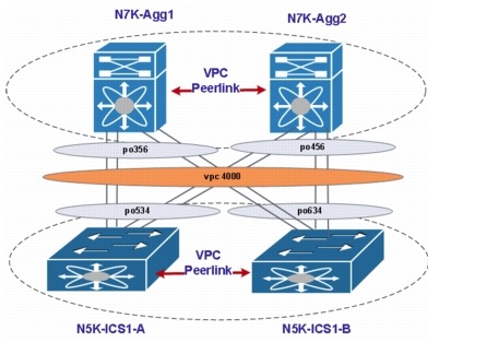
The Nexus 7004 is used in the Aggregation layer and uses vPC technology to provide loop-free topologies. The Nexus 5548 is used in the Access layer and is connected to the Aggregation layer using back-to-back vPC. Figure 3-1 shows the entire vPC topology that is used in the Aggregation and Access layers.
Figure 3-1 vPC Topology in the Aggregation and Access Layers
The main difference between a vPC configuration and a non-vPC configuration is in the forwarding behavior of the vPC peer link and the Bridge Protocol Data Unit (BPDU) forwarding behavior of vPC member ports only.
A vPC deployment has two main spanning-tree modifications that matter:
•vPC imposes the rule that the peer link should never be blocking because this link carries important traffic such as the Cisco Fabric Services over Ethernet (CFSoE) protocol. The peer link is always forwarding.
•For vPC ports only, the operational primary switch generates and processes BPDUs. The operational secondary switch forwards BPDUs to the primary switch.
The advantages of Multiple Spanning Tree (MST) over Rapid Per-VLAN Spanning Tree Plus (PVST +) are as follows:
•MST is an IEEE standard.
•MST is more resource efficient. In particular, the number of BPDUs transmitted by MST does not depend on the number of VLANs, as Rapid PVST+ does.
•MST decouples the creation of VLANs from the definition for forwarding the topology.
•MST simplifies the deployment of stretched L2 networks, because of its ability to define regions.
For all these reasons, it is advisable for many vPC deployments to migrate to an MST-based topology.
Rapid PVST+ offers slightly better flexibility for load balancing VLANs on a typically V-shape spanning-tree topology. With the adoption of vPC, this benefit is marginal because topologies are becoming intrinsically loop free, at which point the use of per-VLAN load balancing compared to per-instance load balancing is irrelevant (with vPC, all links are forwarding in any case).
In our implementation, we have used two instances in MST. MST0 is reserved and is used by the system for BPDU processing. Within each MST region, MST maintains multiple spanning-tree instances. Instance 0 is a special instance for a region, known as the IST. The IST is the only spanning-tree instance that sends and receives BPDUs. MST 1 has all of the VLAN instances (1-4094) mapped to it. Since the per-VLAN benefits are marginal compared to per-instance load balancing, we prefer to use a single MST instance (MST1).
The following configuration details the MST and vPC configuration used on the Nexus 7004 (Aggregation) switch:
spanning-tree mode mst
spanning-tree mst 0-1 priority 0
spanning-tree mst configuration
name dc2
instance 1 vlan 1-4094
interface port-channel456
description PC-to-N5K-VPC
switchport
switchport mode trunk
switchport trunk allowed vlan 1-1120,1601-1610,1801-1860,2001-2250
switchport trunk allowed vlan add 3001-3250
spanning-tree port type network
service-policy type qos input ingress-qos-policy
service-policy type queuing output vmdc23-8e-4q4q-out
vpc 4000
The following details the MST and vPC configuration used on the Nexus 5548 (ICS) switch:
interface port-channel534
description vPC to N7K-Aggs
switchport mode trunk
spanning-tree port type network
speed 10000
vpc 4000
spanning-tree mode mst
spanning-tree mst 0 priority 4096
spanning-tree mst configuration
name dc2
instance 1 vlan 1-4094
The salient features of the connection between ICS and aggregation are as follows:
•Pre-provision all VLAN instances on MST and then create them later as needed.
•The operational secondary switch cannot process BPDUs and it forwards them to the operational primary when they are received.
•Unlike SPT, vPC can have two root ports. The port on the secondary root that connects to primary root (vPC peer link) is a root port.
•Type-1 inconsistencies must be resolved for a vPC to be formed. Associate the root and secondary root role at the Aggregation layer. It is preferred to match the vPC primary and secondary roles with the root and secondary root.
•You do not need to use more than one instance for vPC VLANs.
•Make sure to configure regions during the deployment phase.
•If you make changes to the VLAN-to-instance mapping when vPC is already configured, remember to make changes on both the primary and secondary vPC peers to avoid a Type-1 global inconsistency.
•Use the dual-active exclude interface-vlan command to avoid isolating non-vPC VLAN traffic when the peer link is lost.
•From a scalability perspective, it is recommended to use MST instead of Rapid PVST+.
For more details on STP guidelines for Cisco NX-OS Software and vPC, refer to Chapter 4: Spanning Tree Design Guidelines for Cisco NX-OS Software and Virtual Port-channels. This document explains the best practices and presents the argument for using MST versus Rapid PVST+ as STP.
Layer 2 at Nexus 7004 Aggregation
The Aggregation layer, which is sometimes referred to as the Distribution layer, aggregates connections and traffic flows from multiple Access layer devices to provide connectivity to the MPLS PE routers. In this solution, a pair of Nexus 7004 switches are used as the Aggregation layer devices. The Nexus 7004 is a four-slot switch. In a compact form factor, this switch has the same NX-OS operational features of other Cisco Nexus 7000 Series Switches. The Nexus 7004 offers high availability, high performance, and great scalability. This switch has two dedicated supervisor slots and two I/O module slots. This switch supports Sup2 and Sup2E, and it does not require fabric modules. This switch is only 7 Rack Units (RU) and is designed with side-to-rear airflow.
vPC and Spanning Tree
In this solution, a back-to-back vPC is used between the Nexus 7004 Aggregation layer and ICS Nexus 5500 series switches. The logical view of vPC is that two switches look like one to the other side, and hence both sides see the other as one switch and one port-channel of 8 links connecting to it. This eliminates any loops, and the vPC rules prevent any packet from being looped back. STP is still run in the background to prevent any accidental vPC failure or for non-vPC ports connected together. The Nexus 7004 STP bridge priority is kept higher to elect the Nexus 7004 pair as the root bridge and have all the ICS switches as non-root bridges. All services appliances are connected to the Nexus 7004 using vPC as well. These are connected as edge ports.
To prevent any L2 spanning-tree domain connection with the management L2 domain, the connection from the management network is directly to the UCS and uses disjoint VLANs on the UCS to connect only the management VLANs on these ports facing the management network. One pair of ports is connected to the Nexus 7004 Aggregation layer switches to transport the Application Control Engine (ACE) management VLANs back to the management network. These are connected as a vPC, but also as an access switchport, and hence are edge ports. See ACE 4710 to Nexus 7004 for detailed information about ACE management.
The details of the vPC configuration are discussed below.
See VPC Best Practices Design Guide for additional information.
vPC
A vPC is a logical entity formed by L2 port-channels distributed across two physical switches to the far-end attached device (Figure 3-2).
Figure 3-2 vPC Terminology
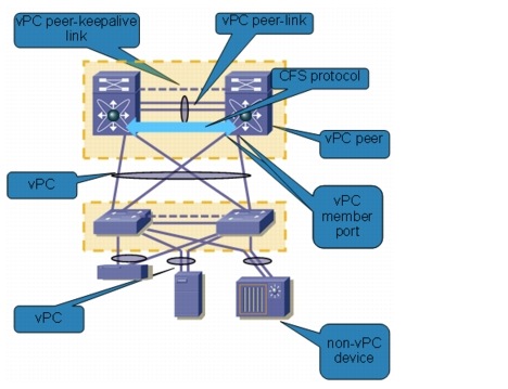
The following components make up a vPC:
•vPC peer. A vPC switch, one of a pair.
•vPC member port. One of a set of ports (port-channels) that form a vPC.
•vPC. The combined port-channel between the vPC peers and the downstream device.
•vPC peer-link. The link used to synchronize the state between vPC peer devices; must be 10GbE.
•vPC peer-keepalive link. The keepalive link between vPC peer devices, i.e., backup to the vPC peer-link.
Refer to Configuring vPCs for a detailed vPC configuration guide. Below is the vPC configuration on the Nexus 7000 switch.
feature vpc
vpc domain 998
peer-switch
role priority 30000
peer-keepalive destination 192.168.50.21
delay restore 120
peer-gateway
auto-recovery
delay restore interface-vlan 100
ip arp synchronize
interface port-channel34
vpc peer-link <=========================vPC peer link
interface port-channel35
  vpc 35                                       <=========================vPC link 35
port-channel 35 for ASA
interface port-channel111
  vpc 111                                      <=========================vPC link 111
port-channel 111 for ACE mgmt
interface port-channel356
  vpc 4000                                     <=========================vPC link 4000
port-channel 356 to the N5K
Below are useful commands for configuring vPCs.
show vpc brief
show vpc role
show vpc peer-keepalive
show vpc statistics
show vpc consistency-parameters

Note 1. vPC peer-keepalive link implementation. The peer-keepalive link between the vPC peers is used to transmit periodic, configurable keepalive messages. L3 connectivity between the peer devices is needed to transmit these messages. In this solution, management VRF and management ports are used.
2. peer switch. See the Spanning Tree Protocol Interoperability with vPC section below.
3. delay-restore. This feature will delay the vPC coming back up until after the peer adjacency forms and the VLAN interfaces are back up. This feature avoids packet drops when the routing tables may not be converged before the vPC is once again passing traffic.
4. arp sync. This feature addresses table synchronization across vPC peers using the reliable transport mechanism of the CFSoE protocol. Enabling IP Address Resolution Protocol (ARP) synchronize can get faster convergence of address tables between the vPC peers. This convergence is designed to overcome the delay involved in ARP table restoration for IPv4 when the peer link port-channel flaps or when a vPC peer comes back online.
5. auto-recovery. This feature enables the Nexus 7000 Series device to restore vPC services when its peer fails to come online by using the auto-recovery command. On reload, if the peer link is down and three consecutive peer-keepalive messages are lost, the secondary device assumes the primary STP role and the primary LACP role. The software reinitializes the vPCs, bringing up its local ports. Because there are no peers, the consistency check is bypassed for the local vPC ports. The device elects itself to be the STP primary regardless of its role priority, and also acts as the master for LACP port roles.
6. peer gateway. This feature enables vPC peer devices to act as the gateway for packets that are destined to the vPC peer device's MAC address.
7. peer link redundancy. For the peer link, it is better to use two or more links from different line cards to provide redundancy.
8. role priority. There are two defined vPC roles, primary and secondary. The vPC role defines which of the two vPC peer devices processes BPDUs and responds to ARP.
Spanning Tree Protocol Interoperability with vPC
The vPC maintains dual-active control planes, and STP still runs on both switches.
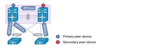
For vPC ports, only the vPC primary switch runs the STP topology for those vPC ports. In other words, STP for vPCs is controlled by the vPC primary peer device, and only this device generates then sends out BPDUs on STP designated ports. This happens irrespectively of where the designated STP root is located. STP on the secondary vPC switch must be enabled, but it does not dictate the vPC member port state. The vPC secondary peer device proxies any received STP BPDU messages from access switches toward the primary vPC peer device.
Both vPC member ports on both peer devices always share the same STP port state (FWD state in a steady network). Port-state changes are communicated to the secondary via Cisco Fabric Service (CFS) messages through peer link. Peer link should never be blocked. As the vPC domain is usually the STP root for all VLANs in the domain, the rootID value is equal to the bridgeID of the primary peer device or secondary peer device. Configuring aggregation on vPC peer devices as the STP root primary and STP root secondary is recommenced. It is also recommended to configure the STP root on the vPC primary device and configure the STP secondary root on the vPC secondary device (Figure 3-3).
Figure 3-3 vPC and STP BPDUs
Peer-switch Feature
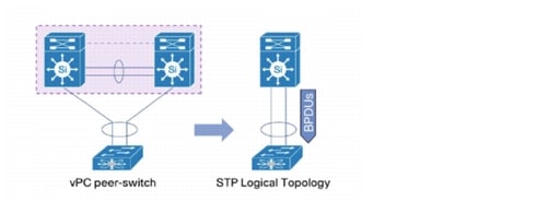
The vPC peer-switch feature address performance concerns around STP convergence. This feature allows a pair of vPC peer devices to appear as a single STP root in the L2 topology (they have the same bridge ID). This feature eliminates the need to pin the STP root to the vPC primary switch and improves vPC convergence if the vPC primary switch fails. When the vPC peer switch is activated, it is mandatory that both peer devices have the exact same spanning tree configuration, and more precisely, the same STP priority for all vPC VLANs.
To avoid loops, the vPC peer link is excluded from the STP computation. In vPC peer switch mode, STP BPDUs are sent from both vPC peer devices to avoid issues related to STP BPDU timeout on the downstream switches, which can cause traffic disruption. This feature can be used with the pure-peer switch topology, in which the devices all belong to the vPC (Figure 3-4).
Figure 3-4 Peer-switch
Spanning Tree Implementation in this Solution
The ASA and ACE do not support spanning tree and configuring the edge trunk port on the Nexus 7000. A pair of Nexus 5000s in vPC mode connects to the pair of Nexus devices in vPC mode in this solution, and this is often referred to as "double-sided vPC" (Figure 3-5).
Figure 3-5 Double-sided vPC
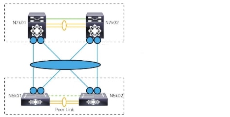
Double-sided vPC simplifies the spanning-tree design, provides a higher resilient architecture, and provides more bandwidth from the Access to Aggregation layer as no ports are blocked.
With the peer-switch feature, the Nexus 7000 switches are placed as the root of the spanning tree in this solution. Figure 3-6 shows the spanning-tree view of the double-sided vPC.
Figure 3-6 Spanning-Tree View of Double-sided vPC
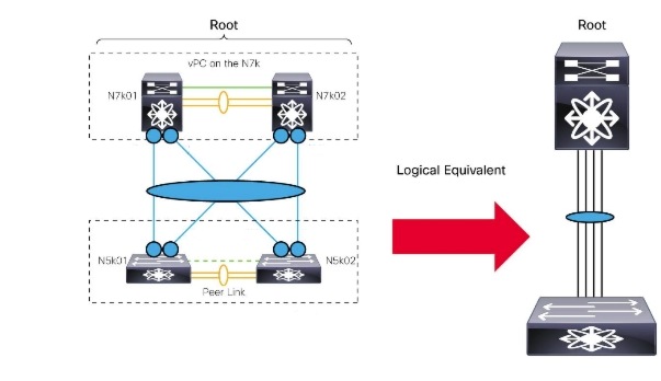
See Layer 2 Implementation at ICS Nexus 5500 for more information about Nexus 7000 to Nexus 5000 connections.
Connecting Service Appliances to Aggregation
In this solution, the Application Control Engine (ACE) 4710 is used to provide the load-balancing service, and the Adaptive Security Appliance (ASA) is used to provide firewall and VPN services.
This section presents the following topics:
ACE 4710 to Nexus 7004
The ACE 4710 has four Gigabit Ethernet interfaces. In this solution, a pair of ACE 4710 devices is used to form active/active redundancy. A vPC is used to connect a pair of ACEs to the Nexus 7004 devices. Figure 3-7 shows the physical connection.
Figure 3-7 Physical Connection
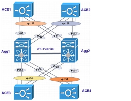
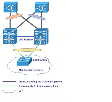
In this diagram, ACE1 and ACE2 are the redundancy pair for the Gold tenants, and ACE3 and ACE4 are the redundancy pair for the Silver tenants. The ACE is not running spanning tree, and there is no loop in this topology, so in the Nexus 7000, the vPC to the ACE is configured as an edge trunk. One pair of ports is connected to the Nexus 7004 Aggregation layer switches to transport the ACE management VLANs back to the management network. These are connected as a vPC, but also as an access switchport, and hence are edge ports. The management switch uses an L3 interface for this ACE management connection to prevent possible spanning-tree loops in the management network.
In this implementation, we are using all four GigabitEthernet ports on the ACE 4710 in a port-channel to connect to the Nexus 7004 aggregation nodes in the DC. This is to enable the full capacity of the ACE 4710 to be available for customer traffic, however, this requires the Fault-Tolerant (FT) VLAN and Management VLAN to also be trunked over this port-channel. For management connectivity, particular attention has to be given and steps taken to avoid merging two different L2 domains and spanning trees. Alternative options are to dedicate one physical interface for Management access, one physical interface for FT traffic, tie them back-to-back between the ACE 4710 pair, and use the other two interfaces available on the ACE 4710 for data traffic, which provides for 2 Gbps of inbound and 2 Gbps of outbound traffic (Figure 3-8). The throughput limit for the ACE 4710 is 4 Gbps. Refer to the Cisco ACE 4710 Application Control Engine Data Sheet for more details.
Figure 3-8 ACE Management Connection
Below is the related configuration on the AGG1 device.
interface port-channel51
description connection to ACE1
switchport
switchport mode trunk
switchport trunk allowed vlan 60,201-210,301-310,401-410,1601-1610
switchport trunk allowed vlan add 1998
spanning-tree port type edge trunk
vpc 51
interface port-channel52
description connection to ACE2
switchport
switchport mode trunk
switchport trunk allowed vlan 60,201-210,301-310,401-410,1601-1610
switchport trunk allowed vlan add 1998
spanning-tree port type edge trunk
vpc 52
interface port-channel53
description connection to ACE3
switchport
switchport mode trunk
switchport trunk allowed vlan 60,501-520,601-620,701-720,1998
spanning-tree port type edge trunk
vpc 53
interface port-channel54
description connection to ACE4
switchport
switchport mode trunk
switchport trunk allowed vlan 60,501-520,601-620,701-720,1998
spanning-tree port type edge trunk
vpc 54
interface port-channel111
description this is for ACE mgmt
switchport
switchport access vlan 60
spanning-tree port type edge
speed 1000
vpc 111
Below is the related configuration on the ACE1 device.
interface port-channel 1
ft-port vlan 1998
  switchport trunk allowed vlan
60,201-210,301-310,401-410,501-520,601-620,701-720,1601-1610
port-channel load-balance src-dst-port
no shutdown
interface gigabitEthernet 1/1
speed 1000M
duplex FULL
qos trust cos
channel-group 1
no shutdown
interface gigabitEthernet 1/2
speed 1000M
duplex FULL
qos trust cos
channel-group 1
no shutdown
interface gigabitEthernet 1/3
speed 1000M
duplex FULL
qos trust cos
channel-group 1
no shutdown
interface gigabitEthernet 1/4
speed 1000M
duplex FULL
qos trust cos
channel-group 1
no shutdown
Below are useful commands for the Nexus 7000 and the ACE.
Nexus 7000
show vpc
show port-channel summary
ACE
show interface
show interface port-channel
ASA 5500/5800 to Nexus 7004
The ASA 5585 is used as the per-tenant firewall, and the ASA 5555 is used as the VPN server for the IPsec and Cisco AnyConnect clients. In this solution, active/active is used to provide redundancy for the firewall purpose, and active/standby is used to provide the VPN server redundancy. To connect to the ASA in the pair, separate port-channels are created in each Nexus 7000. vPC links are used in the Nexus 7000 to connect to the ASA devices. From the view of the ASA, it is using one single port-channel to connect to the Nexus 7000 routers.
Figure 3-9 shows the physical connection.
Figure 3-9 Physical Connection
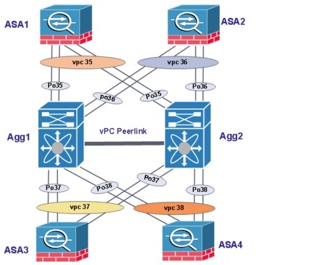
In this diagram, ASA1 and ASA2 are the redundancy pair for the firewall service, and ASA3 and ASA4 are the redundancy pair for the VPN service. The ASA is not running spanning tree, and there is no loop in this topology, so in the Nexus 7000, the vPC to the ASA is configured as an edge trunk.
Below is the related configuration on the Nexus 7000 Agg1 device.
interface port-channel35
description PC-to-FW1
switchport
switchport mode trunk
switchport trunk allowed vlan 1201-1210,1301-1310,1401-1410,1501-1510
switchport trunk allowed vlan add 1701-1710,2000,3001-4000
spanning-tree port type edge trunk
no lacp graceful-convergence
vpc 35
interface port-channel36
description PC-to-FW2
switchport
switchport mode trunk
switchport trunk allowed vlan 1201-1210,1301-1310,1401-1410,1501-1510
switchport trunk allowed vlan add 1701-1710,2000,3001-4000
spanning-tree port type edge trunk
no lacp graceful-convergence
vpc 36
interface port-channel37
description PC-to-VPN1
switchport
switchport mode trunk
switchport trunk allowed vlan 1701-1710,2000
spanning-tree port type edge trunk
no lacp graceful-convergence
vpc 37
interface port-channel38
description PC-to-VPN2
switchport
switchport mode trunk
switchport trunk allowed vlan 1701-1710,2000
spanning-tree port type edge trunk
no lacp graceful-convergence
vpc 38
Note By default, LACP graceful convergence is enabled. In this solution, we disable it to support LACP interoperability with devices where the graceful failover defaults may delay the time taken for a disabled port to be brought down or cause traffic from the peer to be lost.
Below is the related configuration on the ASA1 device.
interface TenGigabitEthernet0/6
channel-group 1 mode active
!
interface TenGigabitEthernet0/7
channel-group 1 mode active
!
interface TenGigabitEthernet0/8
channel-group 1 mode active
!
interface TenGigabitEthernet0/9
channel-group 1 mode active
interface Port-channel1
port-channel load-balance vlan-src-dst-ip-port
Below are useful commands for the Nexus 7000 and ASA.
Nexus 7000
show port-channel summary show vpc
ASA
show interface port-channel
Port-Channel Load-Balancing
The port-channel (EtherChannel) is a port-link-aggregation technology. It allows grouping of several physical Ethernet links to create one logical Ethernet link for the purpose of providing FT and load-balancing links between switches, routers, and other devices. To load balance the traffic, hash schemes are used to select a port member of a bundle that is used for forwarding, and usually they make this decision based on fixed field values of either L2, L3, or Layer 4 (L4) headers, or Boolean operation on fixed field values on two or three protocol headers. To determine which fields to use, traffic analysis should be done to determine the best hash scheme. Load-balancing options differ across different platforms. The following sections discuss Nexus 7000, Nexus 5000, ASA, ACE, and FI port-channel load-balancing techniques.
Nexus 7000 Load-balancing Optimization
The NX-OS software load balances traffic across all operational interfaces in a port-channel by hashing the addresses in the frame to a numerical value that selects one of the links in the channel. The fields that can be used to hash are MAC addresses, IP addresses, or L4 port numbers. It can use either source or destination addresses or ports or both source and destination addresses or ports. Load-balancing mode can be configured to apply to all port-channels that are configured on the entire device or on specified modules. The per-module configuration takes precedence over the load-balancing configuration for the entire device. The default load-balancing method for L3 interfaces is source and destination IP address. The default load-balancing method for L2 interfaces is source and destination MAC address.
In this solution, the Nexus 7000 is configured as follows:
port-channel load-balance src-dst ip-l4port-vlan
Below are useful commands for the Nexus 7000.
dc02-n7k-agg1# sh port-chan load-balance
System config:
Non-IP: src-dst mac
IP: src-dst ip-l4port-vlan rotate 0
Port Channel Load-Balancing Configuration for all modules:
Module 3:
Non-IP: src-dst mac
IP: src-dst ip-l4port-vlan rotate 0
Module 4:
Non-IP: src-dst mac
IP: src-dst ip-l4port-vlan rotate 0
Nexus 5000 Load-balancing Optimization
In the Nexus 5000 switches, NX-OS load balances traffic across all operational interfaces in a port-channel by reducing part of the binary pattern formed from the addresses in the frame to a numerical value that selects one of the links in the channel. Port-channels provide load balancing by default.
The basic configuration uses the following criteria to select the link:
•For an L2 frame, it uses the source and destination MAC addresses.
•For an L3 frame, it uses the source and destination MAC addresses and the source and destination IP addresses.
•For an L4 frame, it uses the source and destination MAC addresses and the source and destination IP addresses.
The switch can be configured to use one of the following methods to load balance across the port-channel:
•Destination MAC address
•Source MAC address
•Source and destination MAC address
•Destination IP address
•Source IP address
•Source and destination IP address
•Destination TCP/UDP port number
•Source TCP/UDP port number
•Source and destination TCP/UDP port number
Traffic analysis needed to be carried out to determine which fields to use. In this solution, the Nexus 5000 is configured as follows:
port-channel load-balance ethernet source-dest-port
Below are useful commands for the Nexus 5000.
dc02-n5k-ics1-A# sh port-channel load-balance
Port Channel Load-Balancing Configuration:
System: source-dest-port
Port Channel Load-Balancing Addresses Used Per-Protocol:
Non-IP: source-dest-mac
IP: source-dest-port source-dest-ip source-dest-mac
ASA Load-balancing Optimization
In the ASA, an 802.3ad EtherChannel is a logical interface (called a port-channel interface) consisting of a bundle of individual Ethernet links (a channel group) to increase the bandwidth for a single network. A port-channel interface is used in the same way as a physical interface when interface-related features are configured. The EtherChannel aggregates the traffic across all available active interfaces in the channel. The port is selected using a proprietary hash algorithm, based on source or destination MAC addresses, IP addresses, TCP and UDP port numbers, and VLAN numbers.
In the ASA, load balancing is configured in the port-channel interface, not in the global device. The default load-balancing method is the source and destination IP address. The following methods can be configured for load balancing:
dc02-asa-fw1(config-if)# port-channel load-balance ?
interface mode commands/options:
dst-ip Dst IP Addr
dst-ip-port Dst IP Addr and TCP/UDP Port
dst-mac Dst Mac Addr
dst-port Dst TCP/UDP Port
src-dst-ip Src XOR Dst IP Addr
src-dst-ip-port Src XOR Dst IP Addr and TCP/UDP Port
src-dst-mac Src XOR Dst Mac Addr
src-dst-port Src XOR Dst TCP/UDP Port
src-ip Src IP Addr
src-ip-port Src IP Addr and TCP/UDP Port
src-mac Src Mac Addr
src-port Src TCP/UDP Port
vlan-dst-ip Vlan, Dst IP Addr
vlan-dst-ip-port Vlan, Dst IP Addr and TCP/UDP Port
vlan-only Vlan
vlan-src-dst-ip Vlan, Src XOR Dst IP Addr
vlan-src-dst-ip-port Vlan, Src XOR Dst IP Addr and TCP/UDP Port
vlan-src-ip Vlan, Src IP Addr
vlan-src-ip-port Vlan, Src IP Addr and TCP/UDP Port
To determine which fields to use, traffic analysis should be done to determine the best hash scheme. In this solution, the ASA is configured as follows:
interface Port-channel1
port-channel load-balance vlan-src-dst-ip-port
Below are useful show commands.
dc02-asa-fw1# sh port-channel 1 load-balance
EtherChannel Load-Balancing Configuration:
vlan-src-dst-ip-port
EtherChannel Load-Balancing Addresses UsedPer-Protocol:
Non-IP: Source XOR Destination MAC address
IPv4: Vlan ID and Source XOR Destination IP address and TCP/UDP (layer-4)port number
IPv6: Vlan ID and Source XOR Destination IP address and TCP/UDP (layer-4)port number
ACE Load-balancing Optimization
An EtherChannel bundles individual L2 Ethernet physical ports into a single, logical link that provides the aggregate bandwidth of up to four physical links on the ACE appliance. The EtherChannel provides full-duplex bandwidth up to 4000 Mbps between the ACE appliance and another switch. In the ACE, the load-balance policy (frame distribution) can be based on a MAC address (L2), an IP address (L3), or a port number (L4). Load balancing is configured in the interface level (not the global device level).
The options are as follows:
dc02-ace-1/Admin(config-if)# port-channel load-balance ?
dst-ip Dst IP Addr
dst-mac Dst Mac Addr
dst-port Dst TCP/UDP Port
src-dst-ip Src XOR Dst IP Addr
src-dst-mac Src XOR Dst Mac Addr
src-dst-port Src XOR Dst TCP/UDP Port
src-ip Src IP Addr
src-mac Src Mac Addr
src-port Src TCP/UDP Port
Traffic should be analyzed to determine the best hash scheme. In this solution, the ACE is configured as follows:
interface port-channel 1
port-channel load-balance src-dst-port
Below are useful commands for configuring the ACE.
dc02-ace-1/Admin# sh interface port-channel 1
PortChannel 1:
----------------------------
Description:
mode: Trunk
native vlan: 0
status: (UP), load-balance scheme: src-dst-port
UCS FI Load-balancing Optimization
Load balancing in the UCS Fabric FI is not required/configurable. The UCSM is configured in End-host (EH) mode. In this mode, server VIFs are dynamically pinned to the uplinks by default. The UCSM also allows static pinning with pin-group configuration. The uplinks to upstream networks on the UCS FI are configured as a port-channel. The UCSM does not have configuration option to change the port-channel load-balancing option.
Nexus 1000V Load-balancing Optimization
The Ethernet uplinks of each ESXi/VEM are configured as a MAC-pinning mode port-channel, and no port-channel load-balancing configuration is required for this kind of port-channel. In the default configuration, vEth interfaces are dynamically pinned to the individual member link of the port-channel. Static pinning can be used to better control the traffic flow. The following configuration pins the management/control traffic and Gold tenant traffic to fabric A, while traffic from other tenants is pinned to fabric B:
port-profile type vethernet esxi-mgmt-vmknic
pinning id 0
port-profile type vethernet vmotion
pinning id 0
port-profile type vethernet vsg-data
pinning id 0
port-profile type vethernet vsg-mgmt
pinning id 0
port-profile type vethernet vsg-ha
pinning id 0
port-profile type vethernet gold-profile
pinning id 2
port-profile type vethernet silver-profile
pinning id 3
port-profile type vethernet bronze-profile
pinning id 3
port-profile type vethernet smb-profile
pinning id 3
Layer 2 Best Practices and Caveats
vPC Best Practices
•A vPC peer link is recommended to use ports from different modules to provide bandwidth and redundancy.
•"ip arp synchronize," "peer-gateway," and "auto-recovery" should be configured in the vPC configuration.
•LACP should be used if possible
•It is recommended to disable LACP graceful convergence when the other end of port-channel neighbors are non NX-OS devices.
•Pre-provision all VLANs on MST and then create them as needed.
•On the Aggregation layer, create a root or a secondary root device as usual. Design the network to match the primary and secondary roles with the spanning-tree primary and secondary switches.
•If making changes to the VLAN-to-instance mapping when the vPC is already configured, remember to make changes on both the primary and secondary vPC peers to avoid a Type-1 global inconsistency.
 Feedback