Cisco User Defined Network Plus Deployment Guide
Available Languages
Bias-Free Language
The documentation set for this product strives to use bias-free language. For the purposes of this documentation set, bias-free is defined as language that does not imply discrimination based on age, disability, gender, racial identity, ethnic identity, sexual orientation, socioeconomic status, and intersectionality. Exceptions may be present in the documentation due to language that is hardcoded in the user interfaces of the product software, language used based on RFP documentation, or language that is used by a referenced third-party product. Learn more about how Cisco is using Inclusive Language.
This guide is intended to provide technical guidance to design, deploy, and operate the Cisco® User Defined Network Plus solution leveraging Cisco technology partner Splash Access. It focuses on the steps to enable device-level segmentation for end user devices such as smartphones, tablets, and media streaming devices by first restricting mDNS discovery to a user’s personal network or “room” and then optionally restricting unicast traffic between other personal networks or user defined networks (UDNs).
The User Defined Network Plus solution
Streaming content using technologies such as Google Chromecast or Apple AirPlay is easy for users on a home network. In a shared network environment, such as in higher education dormitories, it can be much harder for a user to find their TV among all the other residents’ devices. This can cause confusion and annoyance, as students can accidentally stream to a device owned by a different student. This problem is not limited to just streaming to a TV but can affect any device using Link Local Multicast protocols.
Cisco’s User Defined Network Plus solution solves this problem by providing each user with their own personal, homelike network on the building’s shared network resources. Users can register and manage their own private network, where only their registered devices can communicate with each other, just as if they were on a home network.
For wireless networks managed by Cisco Meraki™, a solution similar to User Defined Network Plus is known as Wi-Fi Personal Network (WPN), and it works in conjunction with Identity Pre-Shared Key (iPSK). For large-scale deployments, user onboarding is typically done using a self-service portal from Splash Access that allows users to authenticate and create unique PSKs that are pushed to the Meraki dashboard via APIs.
Note: WPN is not part of this document. If you would like to explore the WPN functionality for Meraki-managed wireless networks, check out the following link:
https://documentation.meraki.com/MR/Encryption_and_Authentication/Wi-Fi_Personal_Network_(WPN).
Splash Access is a Cisco Meraki technology partner and has been integrated with Cisco Meraki for the past seven years. Splash Access provides a secure onboarding system and management portal for end users connecting to a WPN-based SSID.
Previously, to deploy the User Defined Network solution it was necessary to have Cisco Catalyst Center, UDN cloud, and the UDN app in addition to the Cisco Catalyst™ 9800 Series Wireless Controller, Cisco access points (Wave 2 or Catalyst 9100), and Cisco Identity Services Engine (ISE).
Splash Access unified user experience
With the Cisco User Defined Network Plus solution, Cisco is simplifying and optimizing the user experience for both Meraki and Catalyst wireless-based deployments. User Defined Network Plus still requires the Catalyst 9800 Series controller, Cisco access points (Wave 2 or Catalyst 9100), and ISE, but the only other requirement is Splash Access. Splash Access integrates with Cisco ISE via APIs.
| When deploying Cisco User Defined Network Plus, discovery and streaming are limited to registered devices within the user’s defined network for wireless devices such as MacBooks, iPhones, and iPads. For Apple TV, if the AirPlay settings are in their default state, devices with Bluetooth enabled and within approximately 30 feet of the Apple TV – or within the signal distance for Bluetooth Low Energy (BLE) – will still be able to discover and stream to an Apple TV registered within a user defined network. Please refer to Appendix C for the procedure to disable AirPlay over Bluetooth if you would like to change this behavior. |
Splash Access
Splash Access communicates with Cisco ISE and is used to create the UDNs. It also registers mobile and other wireless devices as part of the user’s private network.
Identity provider
The identity provider (IdP) is your organization’s single sign-on (SSO) service, which is used for authentication. Microsoft Azure AD and SAML are the supported IdPs for the User Defined Network Plus solution. SAML is compatible with Shibboleth or Microsoft Active Directory Federated Services (ADFS). When a user authenticates using Splash Access and their credentials, the SSO service is queried and results returned. Upon successful authentication, the user can create their UDN “room” and add their devices.
Cisco Identity Service Engine (ISE)
Cisco ISE, a critical component of the User Defined Network Plus solution, allows you to provide highly secure network access to users and devices. It helps you gain visibility into what is happening in your network, such as who is connected, which applications are installed and running, and much more. It also shares vital contextual data, such as user and device identities, threats, and vulnerabilities with integrated solutions from Cisco technology partners, so you can identify, contain, and remediate threats faster.
In addition to serving as an organization’s RADIUS server for authentication, authorization, and accounting (AAA), Cisco ISE inspects authentication attributes from the wireless controller to determine if the authenticating device is attempting to join a UDN-enabled SSID. Once confirmed, ISE communicates the information required for UDN segmentation back to the wireless controller.
Catalyst 9800 Series Wireless Controller
Cisco Catalyst 9800 Series Wireless Controllers are based on Cisco IOS® XE and integrate the RF excellence of Cisco Aironet® access points, creating a best-in-class wireless experience. The 9800 Series is built on an open and programmable architecture with built-in security, streaming telemetry, and rich analytics.
| Tech tip |
| The Cisco User Defined Network Plus solution supports the Catalyst 9800 Series only when it is running in Local mode. Cisco Software-Defined Access (SD-Access) is not supported if fabric-enabled wireless has been deployed. Cisco User Defined Network Plus is supported if the wireless in an SD-Access fabric has been deployed as over the top using Local mode, with both control and data plane encapsulated in a Control and Provisioning of Wireless Access Points (CAPWAP) tunnel between the access point and Catalyst 9800 Series Wireless Controller. |
Cisco access points
The Cisco User Defined Network Plus solution supports all Cisco Wave 2 access points, most notably the Cisco Aironet 1800, 2800, 3800, and 4800 Series, as well as Cisco Catalyst 9100 Wi-Fi 6/6E access points.
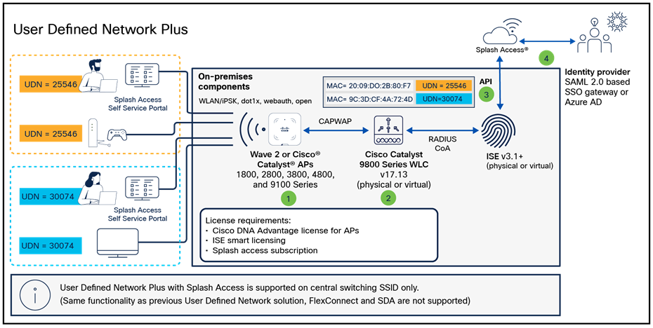
The Cisco User Defined Network Plus solution incorporates the Catalyst 9800 Series controllers, Splash Access, and ISE components to provide segmented, personal networks in which users’ mobile devices and streaming entertainment devices are isolated from one another by limiting multicast advertisement of services and optionally providing unicast blocking of communications between those segmented, personal networks (referred to as UDNs). Splash Access is used for device registration and de-registration. The Cisco User Defined Network Plus solution’s on-premises components include Catalyst 9800 Series controllers, Wave 2 or Catalyst 9100 access points, and Cisco ISE for network access control through RADIUS AAA.
Device registration and onboarding in the User Defined Network Plus solution
Cisco Identity Services Engine
In addition to providing RADIUS AAA services for user/device authentication, Cisco ISE is responsible for three other functions in the User Defined Network Plus solution:
1. ISE processes device registration and room assignment/change requests from information forwarded from Splash Access across all ISE policy service nodes in the deployment.
2. ISE interacts with the Catalyst 9800 Series controller in RADIUS authentication requests by retrieving UDN assignments for onboarding end user devices from its local database.
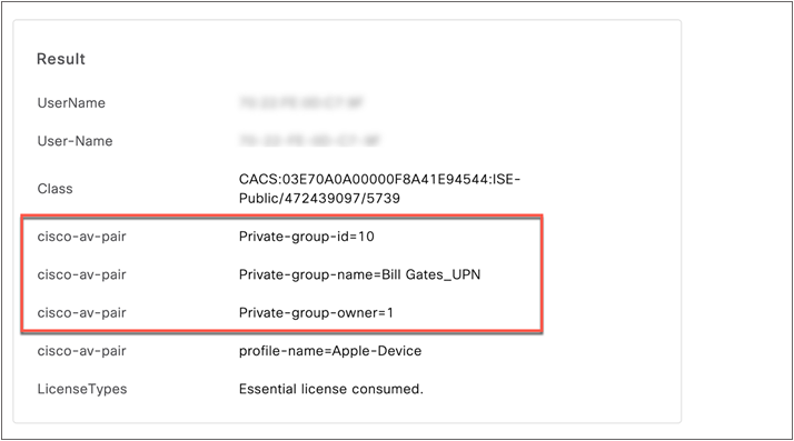
3. Upon successful authentication, ISE sends a RADIUS response to the wireless controller containing three UDN vendor-specific attributes (VSAs) used for UDN segmentation at the wireless controller and access point.
● cisco-av-pair = UDN:Private-group-id (UDN ID used to separate multicast/broadcast domains)
● cisco-av-pair = UDN:Private-group-name (The UDN “name” of the room created by a user)
● cisco-av-pair = UDN:Private-group-owner (Identifies if the device is the owner of the UDN)
There are some manual, UDN-specific configurations required for ISE and Splash Access. All User Defined Network Plus and device registration configuration is performed via the Splash Access service. A new User Defined Network Plus pxGrid service is added that allows both ISE and Splash Access to communicate with ISE via REST APIs. ISE makes use of a new pxGrid “status” topic whenever User Defined Network Plus assignments are created, updated, or deleted.
Upon Splash Access integration with ISE, two new database tables are created. The first is for Device-UDN assignment records based on MAC addresses; this is used for device authentication. The second table is for UDN properties for which UDN is enabled and, if so, the wireless controller and SSIDs it is enabled on; this is used to check whether the authentication request received has originated from a UDN-enabled WLC or SSID requiring the extra UDN device lookup. Both database tables are replicated across a distributed ISE deployment.
Catalyst 9800 Series wireless controller
The Cisco User Defined Network Plus solution requires Cisco IOS XE-based Catalyst 9800 Series wireless controllers, either physical or virtual; AireOS-based controllers and Catalyst 9800 embedded (switch or access point) controllers are not supported. With the introduction of User Defined Network Plus, SSIDs can be defined and dedicated to UDNs in addition to those SSIDs dedicated to normal enterprise and guest wireless access. The UDN SSIDs can be configured for 802.1X, MAC Authentication Bypass (MAB), or PSK or iPSK. Prior to UDN+, only a single Catalyst 9800 Series controller or High Availability (HA) pair was supported. As a result, all devices and their UDNs are local to the WLC and the specific SSIDs associated with the UDNs, so roaming between controllers is not supported.
The mDNS Gateway functionality of the Catalyst 9800 Series WLC is completely interoperable with the User Defined Network Plus functionality. The gateway functionality must be configured separately. The mDNS Gateway functionality is required for advertisement of Bonjour services across Layer 3 networks. If your UDN+ deployment is deployed across multiple VLANs, mDNS Gateway will be required if devices in a UDN will need to discover devices in another VLAN.
| Tech tip |
| For more information regarding mDNS, please refer to the mDNS Deployment Guide for Cisco Catalyst 9800 Series WLCs. |
If a user registered their device offsite using the Splash Access portal, that device can access the User Defined Network Plus SSID upon connecting to the wireless network. If, however, due to MAC randomization they were unable to pre-register their device, the user can connect their device to any SSID providing internet access and register the device once attached to the wireless network. The SSID joined for registration while onsite could be the UDN SSID or any other, as long as the user has the credentials necessary to access the organization’s wireless network based on the security implemented.
Once a device successfully registers and connects to the UDN SSID, the wireless controller sends a RADIUS authentication request to Cisco ISE. In addition to the authentication method (802.1X, MAB, or PSK) based on the wireless security configured for the UDN SSID, ISE performs a lookup for that device’s MAC address and returns the authentication results as well as the RADIUS UDN-ID to the wireless controller if the MAC address is found in the ISE database. Splash Access populates the MAC addresses in the ISE identity database at the time of device registration. If no UDN information is associated with a device from Splash Access, ISE will not relay any specific UDN information back to the wireless controller and the device will be granted access upon successful authentication.
When joining the UDN SSID, if authentication is successful but the device is not registered to a user’s network, the device will still gain access to the network and will be assigned a UDN-ID of zero. With a UDN-ID of zero, the device will be able to communicate in north/south fashion to the internet and wired enterprise resources. It will not be able to communicate with any other wireless devices within that UDN SSID.
When devices associated with a specific UDN attach to the UDN SSID, the controller will segment the various discovery protocol traffic, such as mDNS, to only that UDN. This will work across all Wave 2 and Catalyst 9100 access points. As a result, only those devices within a specific UDN will see the services broadcasted by any device within that UDN. Segmentation of multicast and broadcast advertisements is performed directly on the Cisco access points. Unicast controls are implemented at the wireless controller.
By default, unicast traffic is permitted between UDNs, while multicast traffic, such as mDNS, is always contained within the UDN. This default behavior of allowing unicast communications between UDNs can be changed during configuration of the UDN at the WLAN policy profile in the wireless security policy associated with the UDN WLAN. With unicast blocking enabled, mobile devices can communicate only with other devices in the same UDN or anything northbound, external to the wireless network.
Device registration and onboarding
This section provides an overview of the communications during device registration and subsequent attachment to the wireless network.
1. Using the Splash Access device registration portal, the device registers with Splash Access.
2. Splash Access authenticates the user either against Azure AD or an IDP via SAML 2.0.
3. The user’s network is created, and all devices’ MAC address information for that UDN are collected. This can be performed offsite, before any device attaches to that user’s network, if MAC randomization is disabled on the device, or onsite where MAC randomization can be enabled.
4. Upon device registration, Splash Access communicates with Cisco ISE, which in turn relays registration information for the device, including the UDN-ID, UDN name, and MAC addresses entered or if iPSK is used.
5. Registration information is then passed to Cisco ISE and stored in a database for later use when devices join the SSID and gain access to the wireless network.
1. When the device is onsite, the UDN SSID will be selected at the device. The SSID can be configured with either a PSK, 802.1X, or MAB flow to authenticate the device.
2. A RADIUS authentication request is sent from the wireless controller to ISE.
3. ISE checks its database to perform a lookup of the MAC address in its endpoint database.
4. Upon a successful lookup, ISE passes the RADIUS response back to the wireless controller along with vendor-specific attributes identifying the
● private-group-id: Used by the wireless controller to identify the user’s network and isolate multicast and broadcast traffic between UDNs
● private-group-name: Name of the “room” or UDN
● private-group-owner: If the UDN is owned by that device
5. The wireless controller programs the access point with the appropriate UDN information to block multicast and broadcast traffic between UDNs.
The following table provides the software versions validated within this deployment guide.
Table 1. Supported software versions
| Device or component |
Version |
| Cisco Catalyst Center |
2.3.5.5 or later |
| ISE |
3.1 Patch 4 or later |
| Catalyst 9800 Series Wireless Controller |
Cisco IOS XE 17.13.X or later with Cisco DNA Advantage licenses for access points |
| Cisco wireless access point |
Cisco IOS XE 17.13.3 or later |
| Splash Access subscription |
Cloud-based |
| Identity provider |
Azure AD or SAML 2.0-enabled service |
The following table provides scale numbers for the solution.
Table 2. Scale capability per device
| Device |
Scale |
| Cisco Catalyst 9800-80 |
Up to 64,000 unique UDNs per controller |
| Cisco Catalyst 9800-40 |
Up to 32,000 unique UDNs per controller |
| Cisco Catalyst 9800-L |
Up to 5,000 unique UDNs per controller |
| Cisco Catalyst 9800-CL (private cloud) |
10,000, 32,000, or 64,000 unique UDNs per controller |
| Cisco ISE |
Up to 2 million endpoints |
| Splash Access |
Subscription per access point |
This process details the necessary steps to set up network components for the User Defined Network Plus solution. These include configuring the Catalyst 9800 Series Wireless Controller and ISE and creating a Splash Access administrator account.
● Customers need to request a Splash Access administrator account from Splash Access: https://www.splashaccess.com/request-demo/
● The Catalyst 9800 Series controller should be added to ISE and vice versa. https://www.cisco.com/c/en/us/support/docs/wireless/catalyst-9800-series-wireless-controllers/214490-configure-radius-and-tacacs-for-gui-and.html
● ISE requires a public IP address to communicate with Splash Access, and the firewall should allow Splash Access source IP address 209.94.60.109. This Splash Access IP address can be different for different customer tenants. Also, the following ISE ports should be opened or accessible:
◦ HTTPS: TCP/443
◦ ISE pxGrid: TCP/8910
◦ ERS REST API: TCP/9060
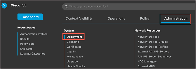
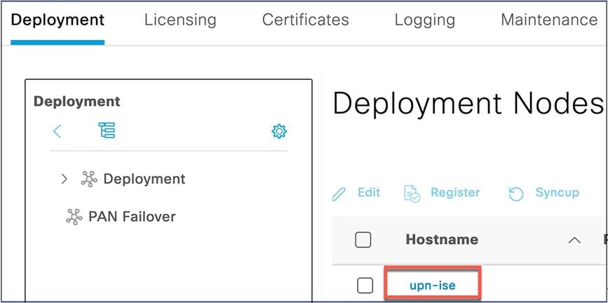
Step 1. Log in to the Cisco ISE Primary Admin Node (PAN) and navigate to Administration > Deployment.
Step 2. Select the hostname of the ISE node.
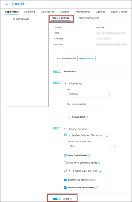
Step 3. Under General Settings, confirm that the pxGrid checkbox is selected or the toggle button is blue, and click Save.
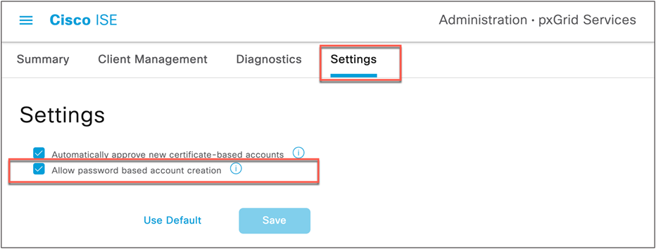
Step 4. Navigate to Administration > pxGrid Services > Settings.
Step 5. Check that Automatically approve new certificate-based accounts and Allow password based account creation are enabled, and click Save.
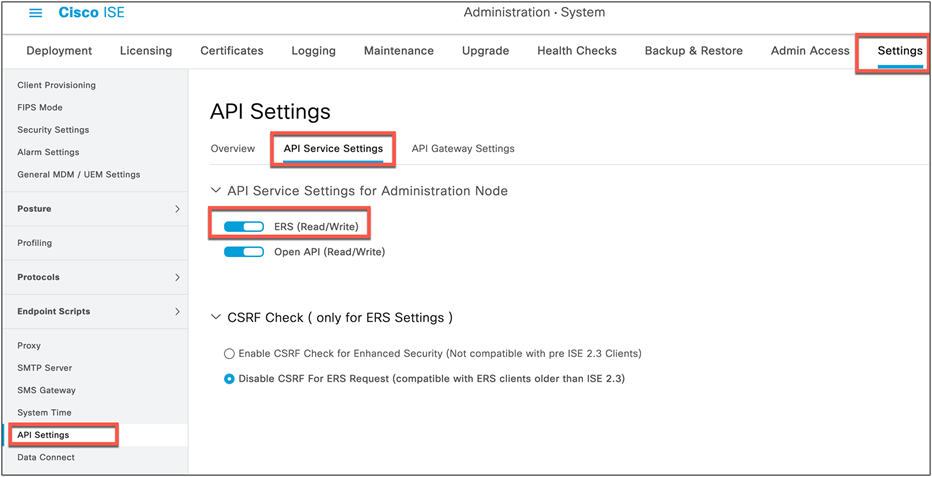
Step 6. Navigate to Administration > System > Settings > API Settings.
Step 7. Enable ERS (Read/Write) and click Save.
Process: Splash Access and ISE integration
A Splash Access admin management account and subscription is required for the User Defined Network Plus solution. Once acquired, proceed by accessing the Splash Access admin portal as described below. https://<customer-account-name>splashudn.com/accounts/<customer-account-name>/management/
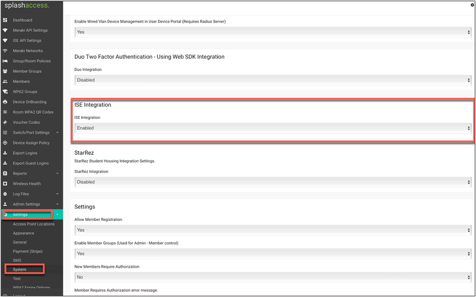
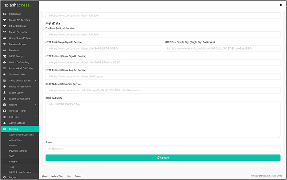
Step 1. Enable ISE in the Splash Access portal. From the main menu, go to Settings > System > ISE Integration and, from the drop-down, select Enabled.
Step 2. Navigate to ISE API Settings in the menu, enter the public IP of ISE, and enter the ISE user credentials for API access. Click Continue.
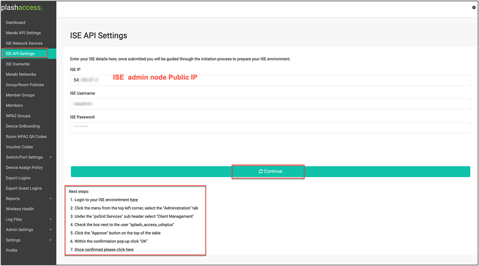
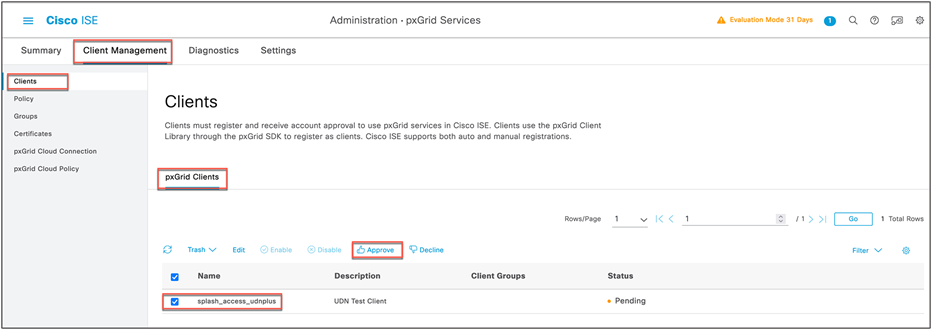
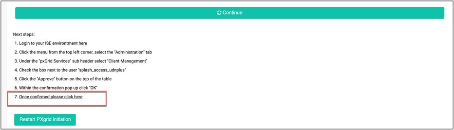
Step 3. Log in to the ISE portal and navigate to Administration > pxGrid Services > Client Management. Check the box next to the "splash_access_udnplus" user. Click Approve.
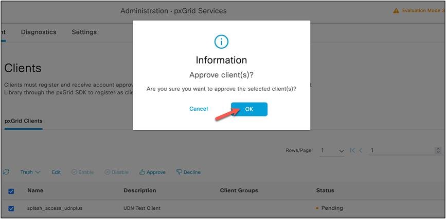
When the confirmation dialog box appears, click OK.
Step 4. When approved from ISE, go to the Splash Access admin portal to confirm the settings by clicking step 7, Once confirmed please click here.
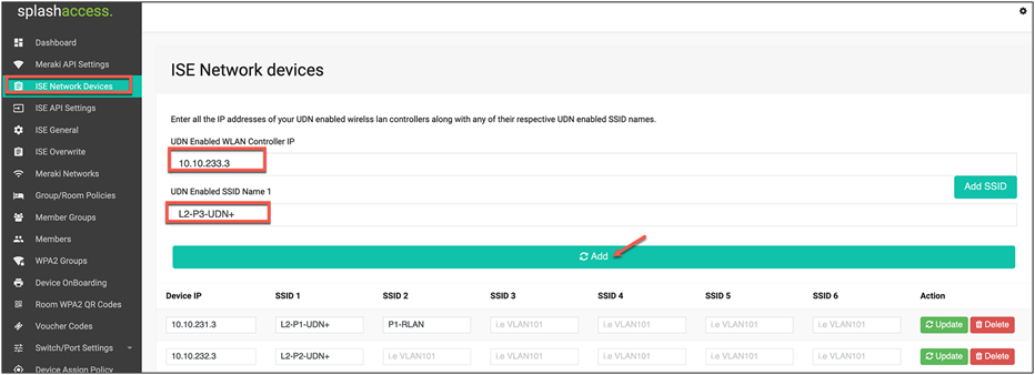
Step 5. Now go to ISE Network Devices and enter the IP addresses of your UDN-enabled WLC, along with any of its respective UDN-enabled WLANs (SSIDs) and remote LAN (RLAN) names.
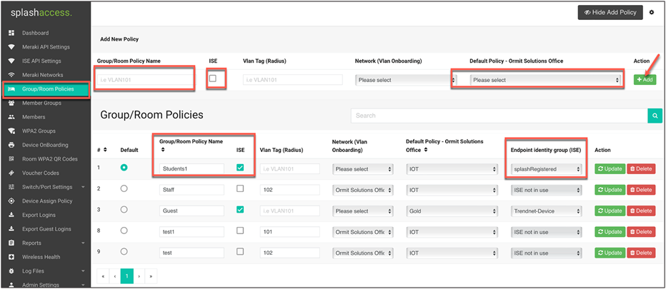
Step 6. Navigate to Group/Room Polices. Create a policy name and match it to the AD group name if required. (This group/room policy name should be the same as configured on your Azure AD.) In the endpoint identity group drop-down, choose the group from which you want to insert devices.
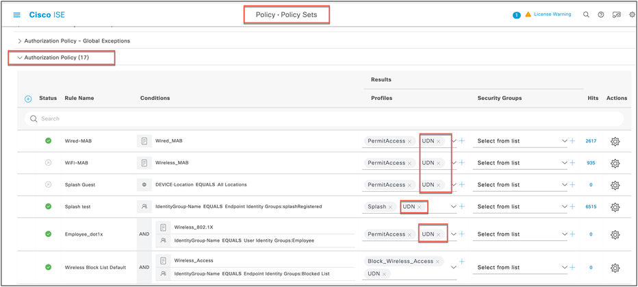
Once the Splash Access and ISE authentication are approved, this process will verify that the UDN authorization profile has been pushed to ISE.
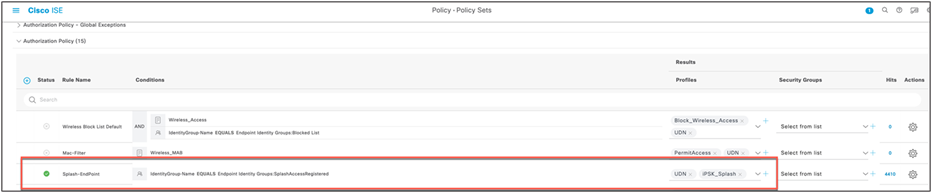
Step 1. Log in to ISE and navigate to Policy > Policy Sets.
Step 2. Click the > next to your Policy Sets and click to expand the authorization policy.
Step 3. Check to see that the UDN authorization profile has been pushed to every policy rule.
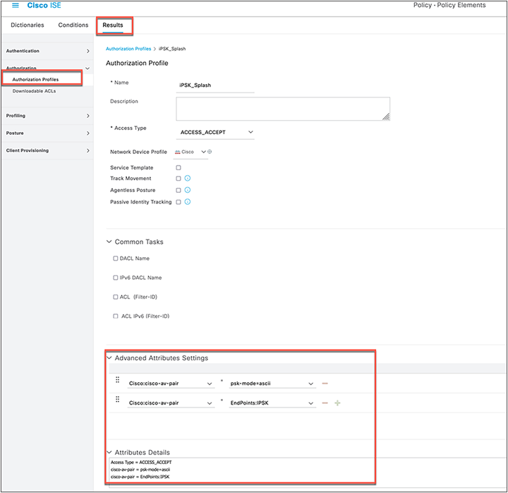
Step 4. (Optional if using iPSK): If iPSK is required or implemented, you will need to create another authorization profile on ISE. Navigate to ISE > Policy > Results > Authorization Profiles, then create an authorization profile for iPSK as follows:
Under Advanced Attributes Settings, create the following:
Cisco:cisco-av-pair = psk-mode=ascii
Cisco:cisco-av-pair = EndPoints:IPSK
Now, in ISE > Policy > Policy Sets, configure an authorization rule that has the UDN and iPSK policy.
Splash Access workflow with ISE pxGrid (reference)
1. User logs in to the Splash Access admin portal and navigates to ISE API Settings
2. User inputs the ISE IP, Port, Username, and Password for the ISE ERS environment
3. Splash system sends POST to https://[ISE IP]:8910/pxgrid/control/AccountCreate for "userName" and "password"
4. Splash system creates a basic auth token by base64 encoding "[userName]:[password]"
5. Splash system sends POST to https://[ISE IP]:8910/pxgrid/control/AccountActivate with basic auth and with "description":"pxGrid REST User" to check for "accountState":"PENDING"
6. User logs in to ISE portal and navigates to Administration > pxGrid Services > Client Management
7. User checks box next to "splash_access_pxgrid" user and clicks "Approve"
8. Splash system sends POST to https://[ISE IP]:8910/pxgrid/control/AccountActivate with basic auth and with "description":"pxGrid REST User" to check for "accountState":"ENABLED"
9. Splash system sends POST to https://[ISE IP]:8910/pxgrid/control/ServiceLookup with basic auth and with "name":"com.cisco.ise.config.upn" to check for "services"[0]"nodeName" value
10. Splash system sends POST to https://[ISE IP]:8910/pxgrid/control/AccessSecret with basic auth and with "peerNodeName":"[nodeName]" to fetch "secret" value
11. Splash system creates new basic auth token by base64 encoding "[userName]:[secret]"
12. Splash system sends POST to https://[ISE IP]:8910/pxgrid/control/AccessSecret with new basic auth and with "upnEnabled":"true"
Splash Access Azure/SAML setup
Administrators can enable and integrate iDPs such as Azure or SAML 2.0-based SSO from Splash Access.
Step 1. From the Splash Access admin dashboard, navigate to Settings > System > Login Systems > System Type and choose the system type from the drop-down. Select Azure or SAML.
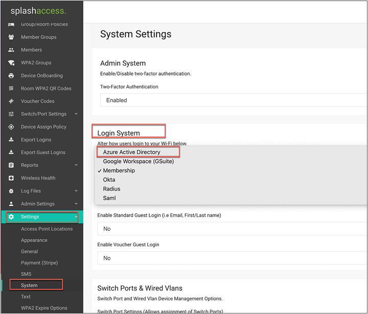
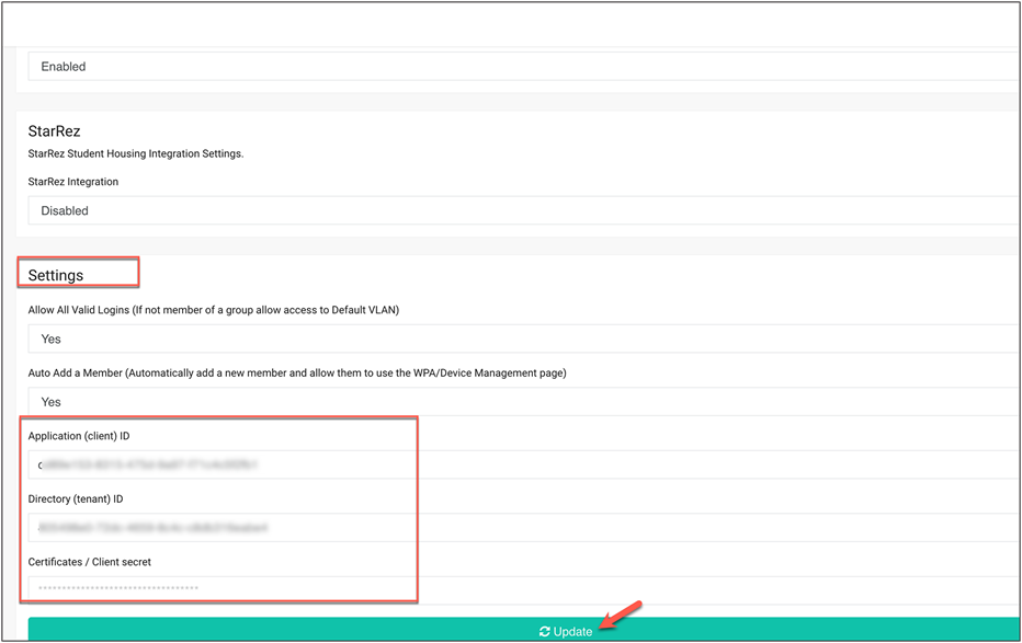
Step 2. Scroll to the bottom of the page and fill in the Azure tenant information or SAML metadata.
The administrator may need to add the Application ID, Tenant ID, and Client secret for Azure.
Splash Access Azure setup
To set up Azure AD with Splash Access, follow the instructions below:
If you wish to use Microsoft 365, you will need to select or create an app under https://portal.azure.com. The system will then redirect users to log in using their Microsoft 365 information.
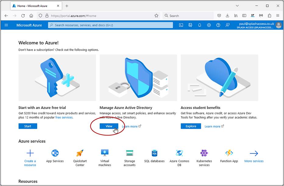
1. Access the Microsoft Azure portal: https://portal.azure.com
2. Navigate to Manage Azure Active Directory and click View.
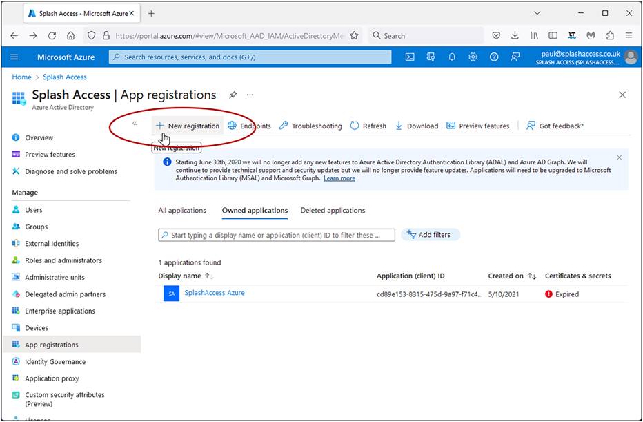
3. Click App registrations in the left column.
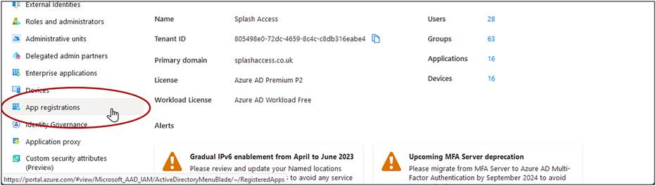
4. Click on the app name, for example, Splash Access, or create a web app or API type application and register it.
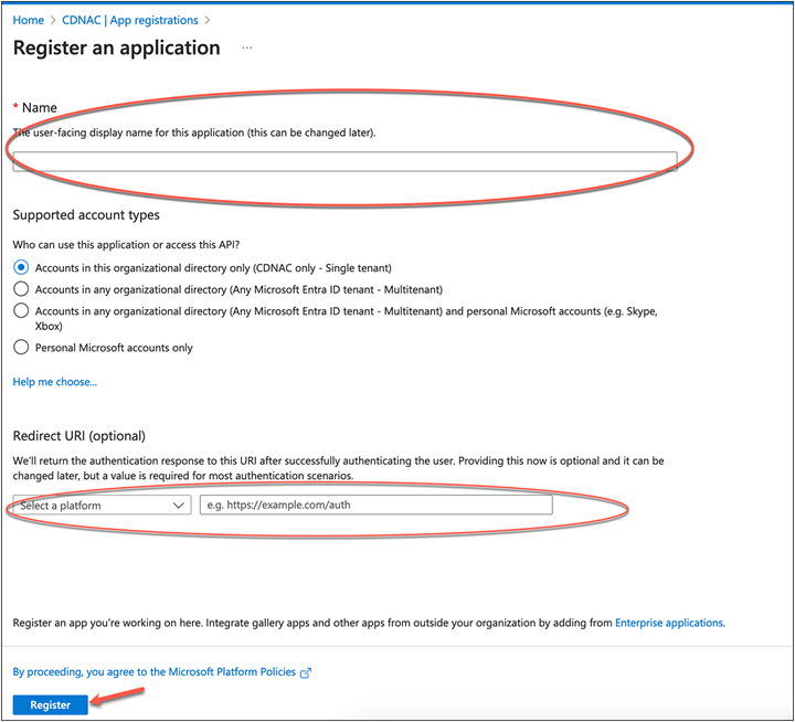
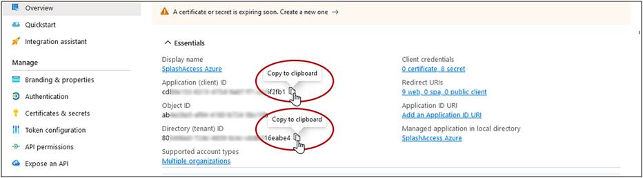
5. Copy the application (client) ID and directory (tenant) ID found on this page by hovering over each and clicking to copy it to the clipboard. Paste them to your notes or paste directly into your Splash Access portal.
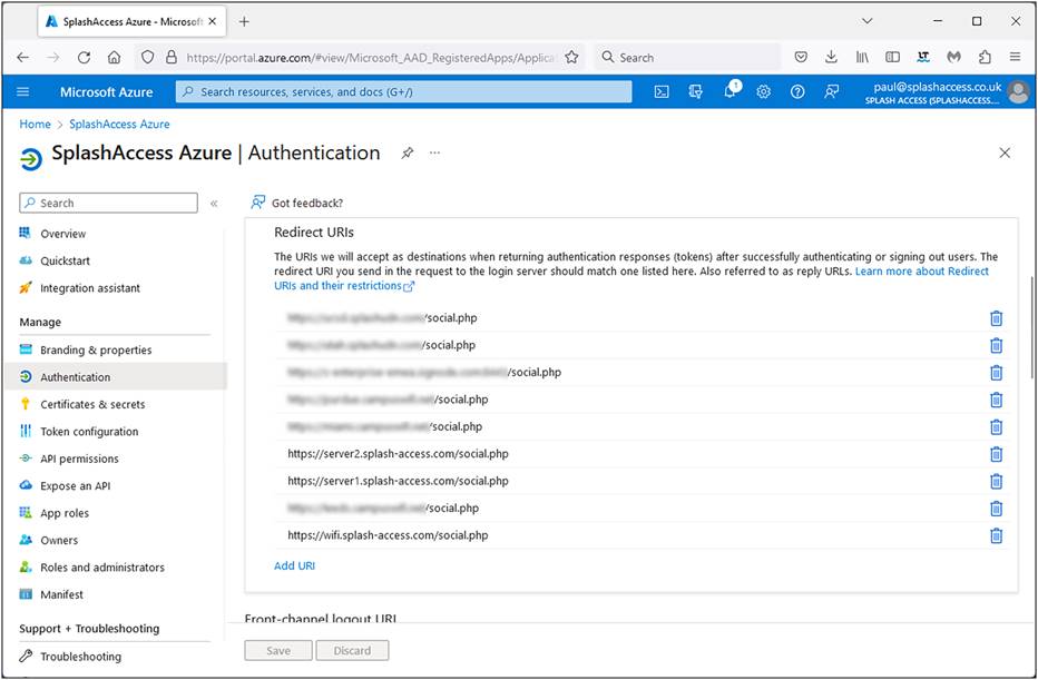
6. Navigate to Authentication > Redirect URIs.
Enter the following, replacing <YourSplashURL> with your account): https://<YourSplashURL>/social.php
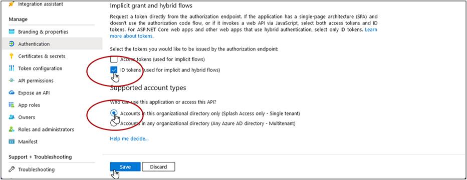
7. Scroll down and enable the checkbox for ID Tokens (used for implicit and hybrid flows).
8. Select Accounts in this organizational directory only (Splash Access only – Single tenant).
9. Click Save.
10. Navigate to Certificates and secrets in the menu.
Generate a new client secret for Splash Access. Enter a name, such as Splash Access, and select the longest period for Expires. Make a note of this date, as you will need to update the secret before it expires.
Click Add.
Note: Keep this key in a safe place along with the above details.
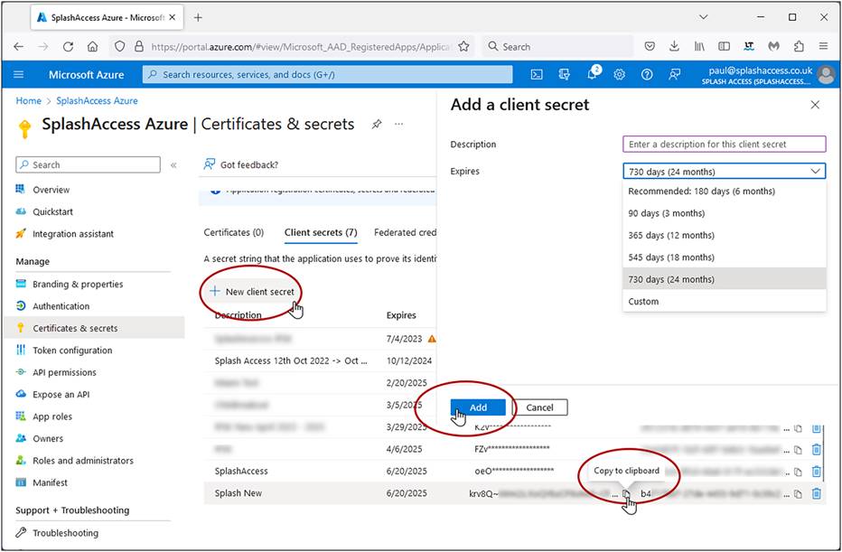
11. Copy the VALUE field into Notepad or other notes or directly into your Splash Access Azure Secret key field.
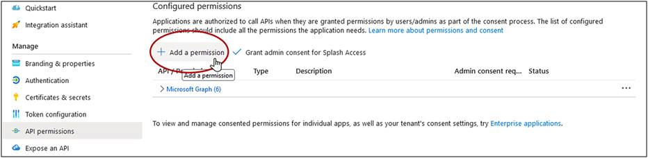
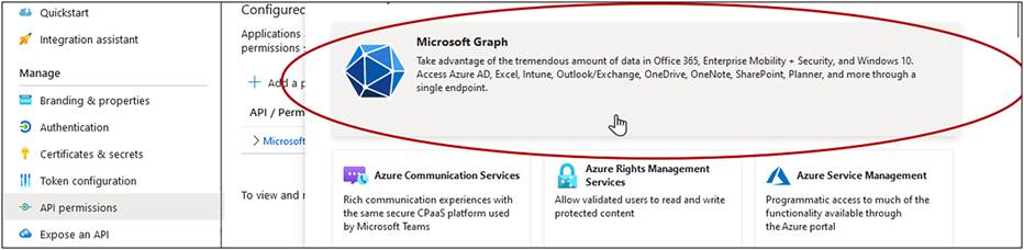
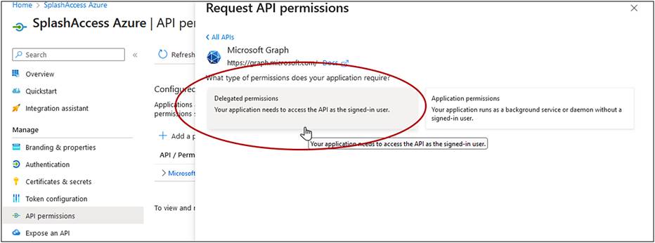
12. Navigate to API Permissions in the menu, click Add a permission, and select Microsoft Graph – Delegated permissions.
Click Grant admin consent for Splash Access.
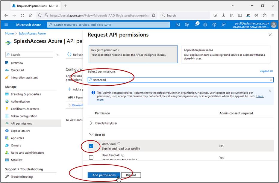
13. Search for and select the following permissions in the Select permissions search bar: Contacts.Read, Directory.Read.All, email, openid, profile, and User.Read. Click Add permissions.
Similarly, for SAML-based authentication, use the MetaData URL for additional configuration from the URL strings.
Enable the User Defined Network Plus solution on the Catalyst 9800 Series
This process will enable the User Defined Network Plus solution configuration on the Catalyst 9800 wireless controller. User defined Network Plus is only supported in central mode deployments, that is, with the access point in Local mode.
Step 1. Log in to the Catalyst 9800 Series WLC.
Navigate to Configuration > Tags & Profiles > WLANs. Select the WLAN where users want to enable their UDN
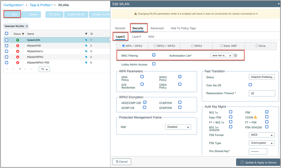
or create a new one by clicking Add. Then go to Security > Layer2. For PSK/iPSK/ Webauth/Open, make sure to select MAC Filtering and Authorization List for the ISE that is used for UDN, and click Update and Apply to Device. For 802.1X, MAC filtering is not required.
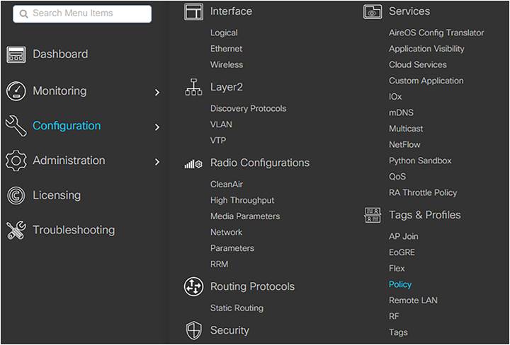
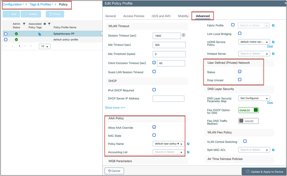
Step 2. Navigate to Configuration > Tags and Profiles > Policy. Click the policy profile that you want to configure and enable User Defined Network Plus on and that needs to be tied to the WLAN for use.
Step 3. Under the Advanced tab, ensure that the User Defined (Private) Network Status box is checked and, optionally, that Drop Unicast is selected. Also, ensure that in AAA Policy, Allow AAA Override is selected and the Policy Name is set to default-aaa-policy. Finally, confirm that Accounting List is set to default.
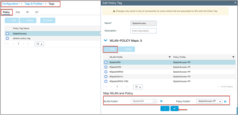
Step 4. Now confirm that the WLAN and policy profile are part of the policy tag where UDN-enabled SSIDs are to be broadcasted. To do this, go to Configuration > Tags & Profiles > Tags.
Process: Configuring an RLAN on the WLC (optional step)
This section is optional and is required only if the customer wants to enable and configure the User Defined Network Plus solution on an RLAN.
A few things to note:
● RLAN workflow is supported in Cisco Catalyst Center Release 2.2.3.
● ISE will not be configured with an RLAN name.
When can we configure an RLAN on the WLC for User Defined Network Plus?
● An RLAN can be configured on the WLC after the access point is provisioned with SSIDs and UDNs.
How do I do this?
Step 1. Configure the RLAN profile and RLAN policy:
1. Log in to the WLC via the GUI.
2. Navigate to Configuration > Tags and Profiles > Remote LAN.
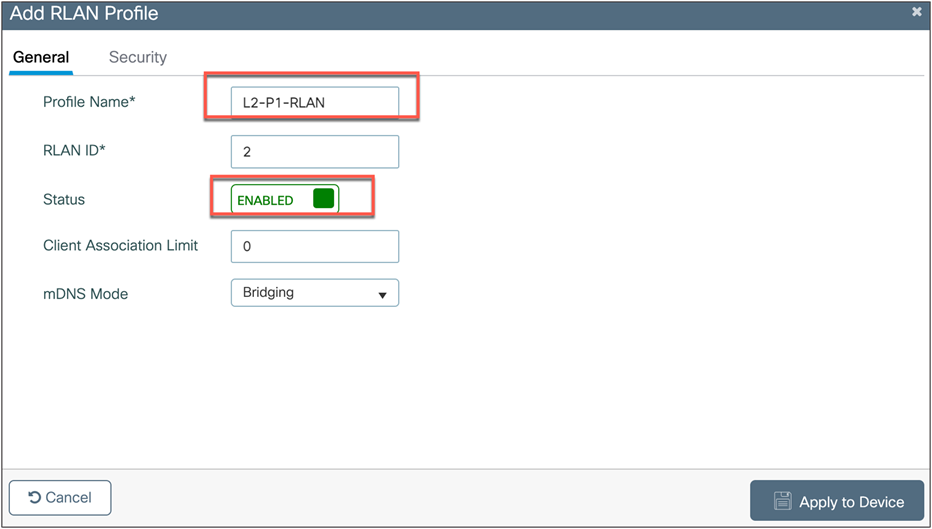
3. On the RLAN Profile tab, click + ADD to create a new RLAN profile.
Create the profiles based on the following configuration. Leave the defaults not mentioned as is.
| Tab |
Setting |
Value |
| General tab |
||
|
|
Profile Name |
Configure name any intuitive to the user |
|
|
Status |
Enabled |
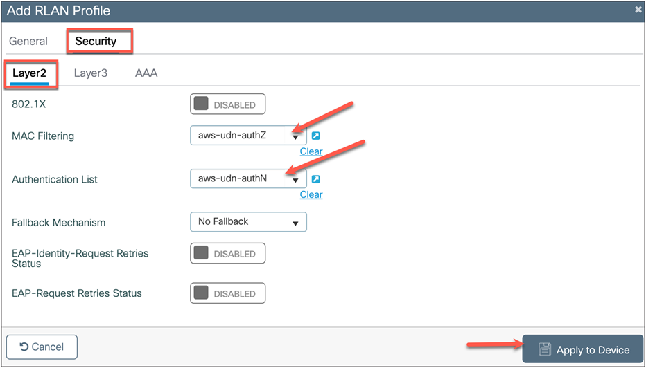
| Security tab > Layer 2 |
||
|
|
802.1X (optional) |
Enable if you want to enable 802.1X on wired clients |
|
|
Mac Filtering (mandatory if 802.1X is not enabled) |
Choose from the configured authorization list |
|
|
Authentication List (required if 802.1X is enabled) |
Choose the configured authentication list |
Click Apply to Device.
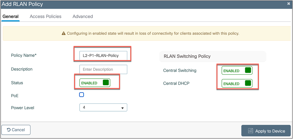
1. On the RLAN Policy tab, click + ADD to create a new RLAN policy.
Create the policy based on the following configuration. Leave the defaults not mentioned as is.
| Tab |
Setting |
Value |
| General tab |
||
|
|
Policy Name |
Configure policy name |
|
|
Status |
Enabled |
|
|
Central Switching |
Enabled |
|
|
Central DHCP |
Enabled |
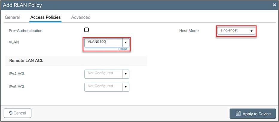
| Access Policies tab |
||
|
|
VLAN |
<VLAN ID> or name |
|
|
Host Mode |
Singlehost: One device per port Multihost: Multiple devices per port (hub) |
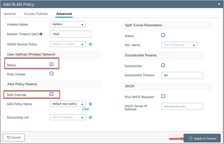
| Advanced tab |
||
|
|
User Defined (Private) Network Status |
Enable to enable UDN |
|
|
Drop Unicast (optional) |
Enable to enable UDN unicast |
|
|
AAA Override |
Enable |
|
|
Accounting List |
Set if required |
Click Apply to Device.
Step 2. Apply the RLAN to the policy profile.
1. Navigate to Configuration > Wireless > Access Points.
Note the policy profile assigned to the access point.
![]()
2. Navigate to Configuration > Tags and Profiles > Tags, then click on the policy tag assigned to the access point.
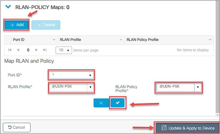
3. Under RLAN-POLICY Maps, click + Add to add a new policy map and configure it with the required port.
| Port ID |
Port number to enable |
| RLAN Profile |
RLAN Profile created in the previous step |
| RLAN Policy Profile |
RLAN Policy created in the previous step |
Click ![]() to add the port configuration.
to add the port configuration.
4. Repeat step 3 if you need to add multiple ports.
5. Click Update and Apply to Device to update the RLAN configuration.
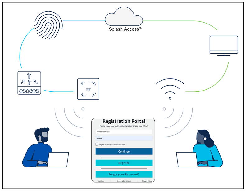
End user device registration with the Splash Access portal
The Splash Access user device registration link/portal is provided to the end user as part of the Splash Access subscription. It mimics the following URL: https://<customer-account>splashudn.com/accounts/<customer-account>/device/
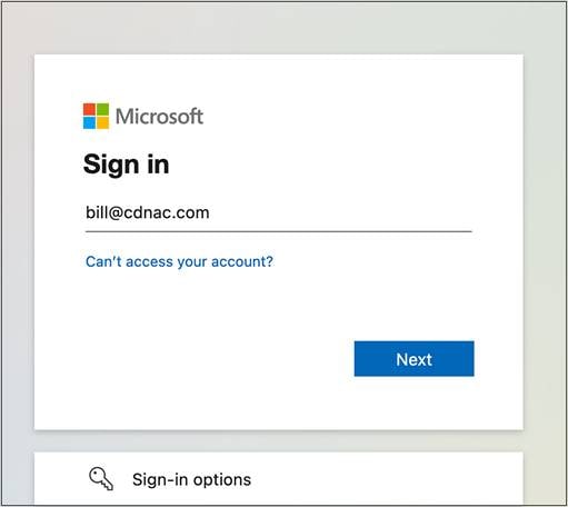
When an end user clicks the link, they will be presented with a web page requiring them to enter their credentials, which can be defined as part of AD.
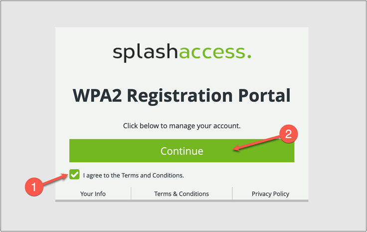
From the user device portal, read the terms and conditions and accept by checking the I agree to the Terms and Conditions box, then click Continue.
The user will be sent to their AD credentials page, where they can enter their provided username and password.
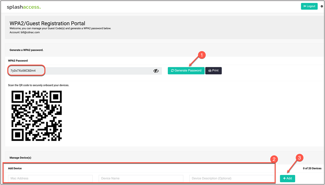
Once an end user is logged in, the Splash Access device registration portal will be displayed.
1. To add the devices, first generate a WPA2 password (iPSK), which is mostly for IoT devices. If the QR code for the SSID was enabled from the Splash Access admin portal, that will also be displayed.
2. The end user can now add their devices by entering their MAC addresses.
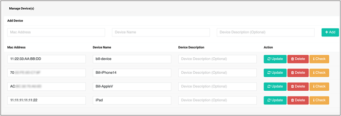
The user can check the device status by clicking the i Check button.
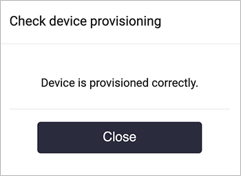
Now when the end user connects to the UDN-enabled SSID, their registered devices will be part of that user’s network or “room,” and only they can access and cast to their own devices.
| Troubleshooting User Defined Network Plus |
This section will go over commands that are useful when troubleshooting the User Defined Network Plus solution.
Catalyst 9800 Series wireless controller
These commands are run on the Catalyst 9800 controller.
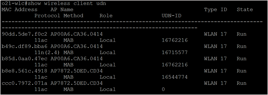
show wireless client udn
This command shows all the clients that are currently connected and the UDNs to which they are connected.
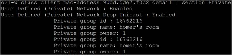
show wireless client mac-address <mac address> detail | section Private
This command can be used to see details on a certain MAC address.
show wireless profile policy detailed <profile-name> | include User
This command can be used to verify that the policy profile is pushed and UDN is enabled.
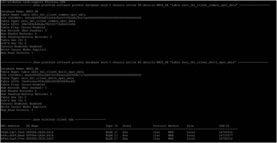
show tech-support wireless udn
This command shows a ton of information that is useful when troubleshooting.
Cisco Identity Services Engine (ISE)
This section will provide troubleshooting information for Cisco ISE.
Turning on User Defined Network Plus debug logs on Cisco ISE
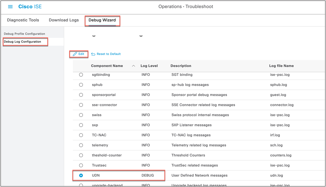
Step 1. On ISE, navigate to Administration > Operations > Troubleshoot > Debug Wizard > Debug Log Configuration and select the ISE node from the list.
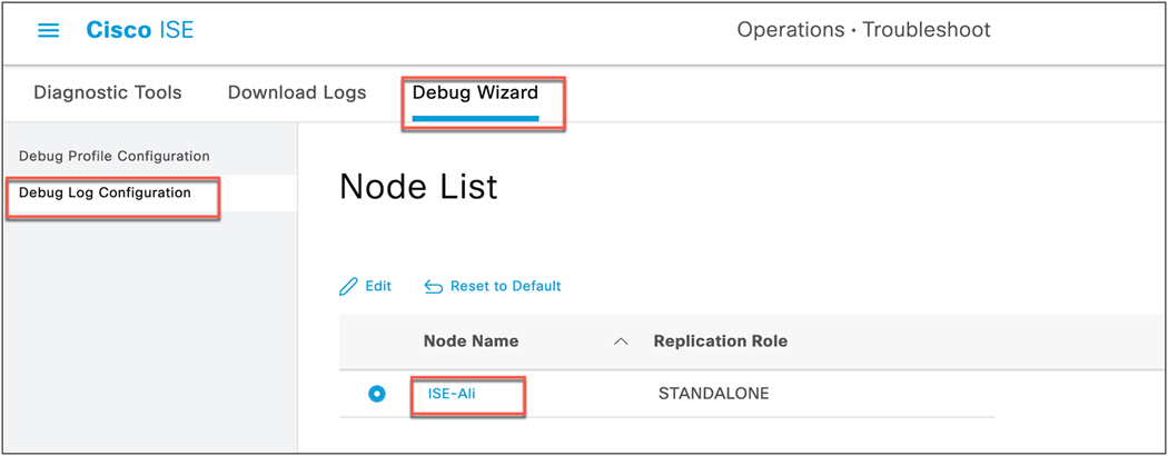
Scroll down the list until you see UDN under Component Name.
Step 2. Change the log level of UDN to DEBUG and click Save.
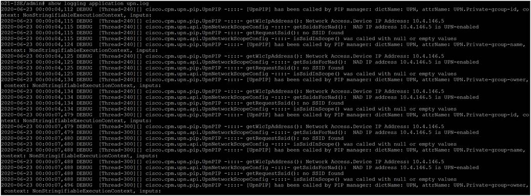
Step 3. With logging enabled, view the logs by accessing the ISE console and entering the command show logging application upn.log.
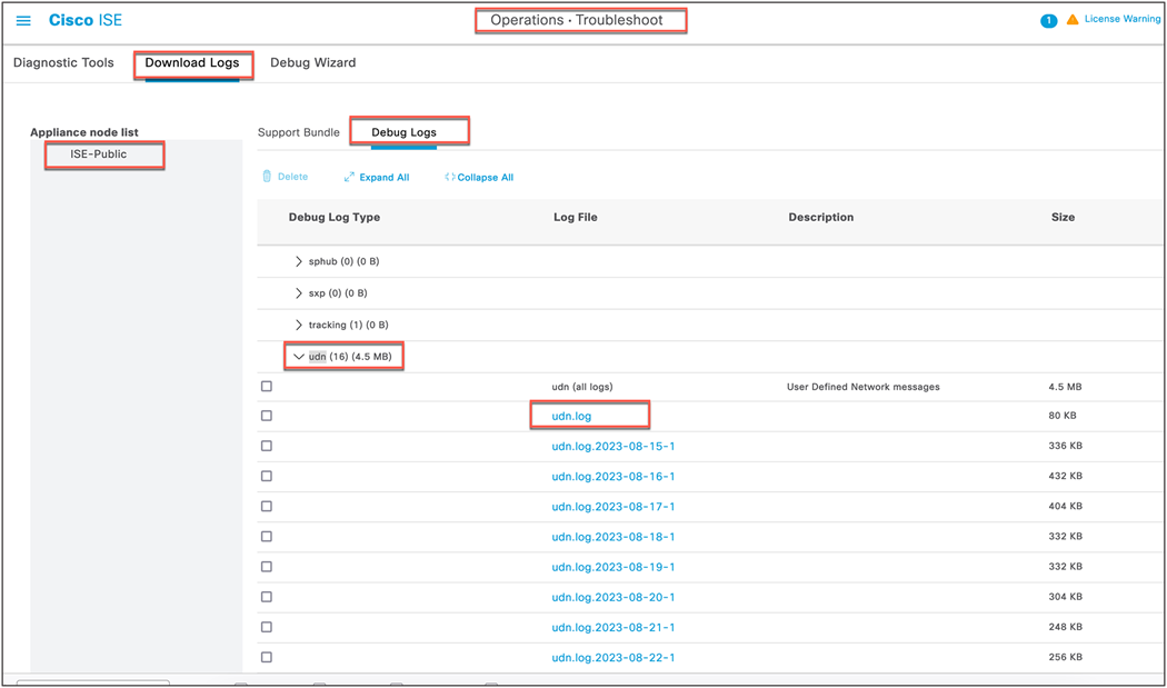
From the ISE dashboard go to Operations > Troubleshoot > Download Logs, select the ISE node from the list, and click Debug Logs.
Under Application logs, select udn and click udn.log to download the log file.
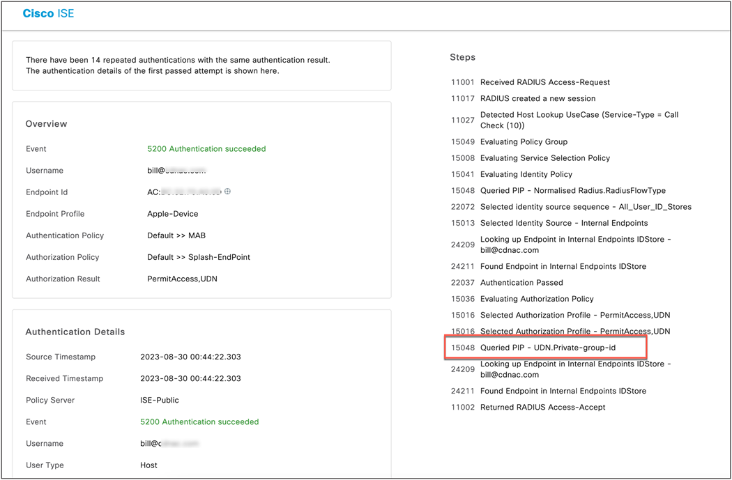
Successful authentication of a registered device:
Successful authentication of an unregistered device:
Appendix A: Configuring mDNS Gateway
Cisco's Service Discovery Gateway, or mDNS Gateway, allows for controlled and secure access to services and devices across subnets. It listens to service announcements on all configured network segments and builds a cache of services and addresses. It proxies these requests to other segments and can also apply filters based on various service attributes. These filters can limit what services will be requested or advertised.
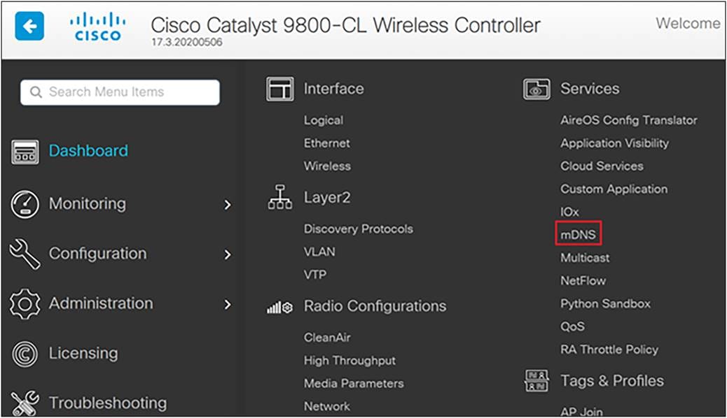
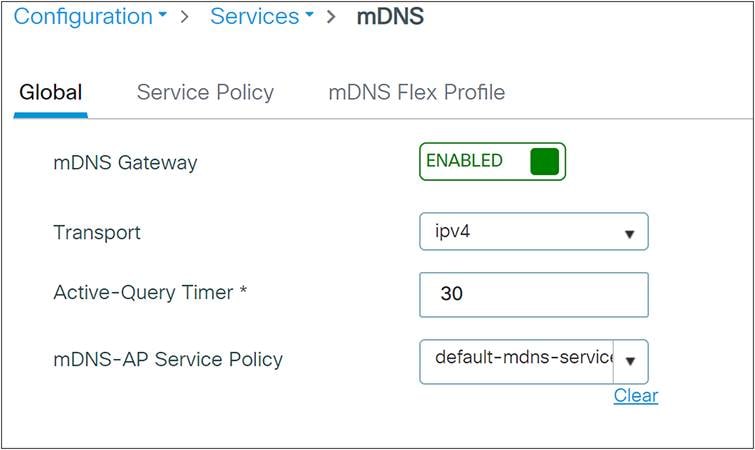
Step 1. In the Catalyst 9800 WLC, navigate to Configuration > Services > mDNS.
Step 2. Under Global, click next to mDNS Gateway to enable it and click Apply. If running IPv6, change the Transport setting to Both.
Step 3. Navigate to Configuration > Tags & Profiles > WLANs.
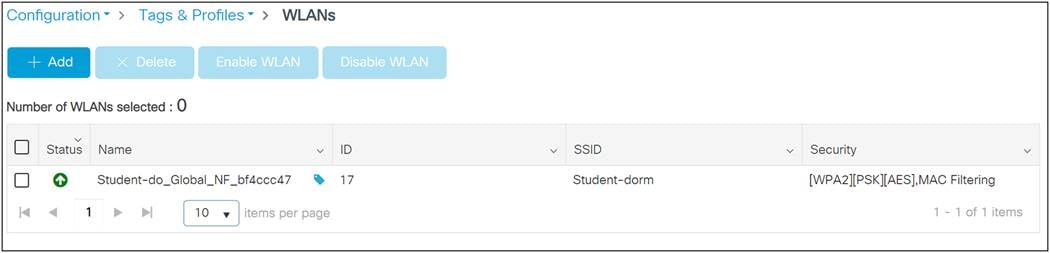
Step 4. Select the WLAN profile on which to enable mDNS Gateway functionality.
Step 5. Select the Advanced tab and change the mDNS Mode drop-down to Gateway. Click Update and Apply to Device when finished.
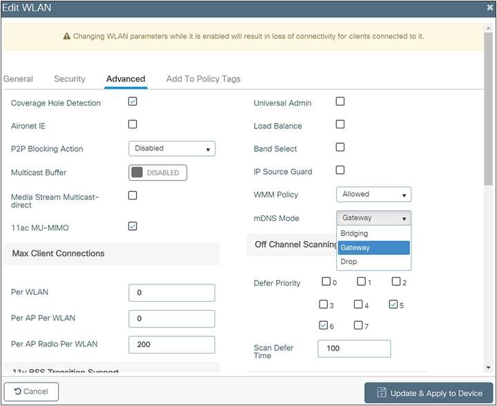
Step 6. These steps enable the default-mdns-service-policy on the WLAN with the following services:
airplay, airtunes, homesharing, printer-ipp, printer-lpd, printer-ipps, printer-socket, google-chromecast, itune-wireless-devicesharing
| Tech tip |
| The Cisco User Defined Network Plus solution does not solve the problem of Universal Plug and Play (UPnP) across VLANs. |
Appendix B: Randomized MAC address
MAC addresses are used to track and log users in public spaces, and this data can be used for marketing purposes or sold to third parties. To prevent this, device manufacturers have implemented random MAC addresses. This makes the user MAC address unique per network, preventing device tracking. The address is kept consistent per network, meaning once a device is associated with an SSID it will not have to authenticate again. This is why, when using a device with a random MAC address with the User Defined Network Plus solution, a device must be connected to the UDN SSID before it can be registered.
Appendix C: Disabling AirPlay discovery and streaming via Bluetooth
By default, Apple TV has AirPlay enabled with discovery via mDNS and streaming over Ethernet or wireless networks as well as Bluetooth. In a home, these settings are optimal for easy connectivity. However, in environments such as university dormitories, hospitals, and long-term healthcare facilities, these default settings will allow other people to not only discover, but stream to a user’s Apple TV if they are on the same wired or wireless network, or within 30 feet of the device (in the case of Bluetooth).
When the Cisco User Defined Network Plus solution is deployed, discovery and streaming is limited to registered devices within the end user’s UDN for wired and wireless devices such as MacBooks, iPhones, and iPads. For Apple TV, however, if the AirPlay settings are left in their default state, devices with Bluetooth enabled and within roughly 30 feet of the Apple TV, the signal distance for Bluetooth Low Energy (BLE), will still be able to discover and stream to an Apple TV registered within a UDN. The outcome, if Bluetooth is left enabled, will be that devices in adjacent rooms, both horizontally and vertically, would likely be able to communicate with the Apple TV.
As the concept of Cisco User Defined Network Plus is to optimize the user experience by displaying only those AirPlay devices within the UDN, it might be optimal for the organization deploying the User Defined Network Plus solution to recommend that Apple TV owners disable Bluetooth on their Apple TVs when installing them in their rooms. Unfortunately, there is no single button or setting to disable Bluetooth on the Apple TV, and so the following procedure details how this is accomplished.
Step 1. From the Apple TV home screen, select Settings.

Step 2. Select AirPlay and HomeKit.
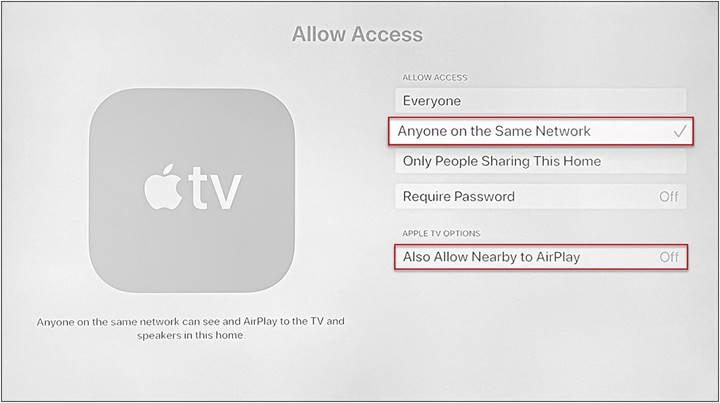
Step 3. Select Allow Access (the default is Everyone).
Step 4. Change from Everyone to Anyone on the Same Network.
Step 5. An Apple TV Options box appears in which you need to change Also Allow Nearby to AirPlay to Off.