Release Notes for Cisco Video Surveillance Manager, Release 7.12
Available Languages
Table of Contents
Release Notes for Cisco Video Surveillance Manager, Release 7.12
Network Attached Storage Support for LTS servers
Camera Discovery: Manual and Scheduled
Bookmarks Automatically Deleted with Video
Real-time Camera Status in Maps
Media Storage Combined into a Single Logical Volume
SASD Option to Filter By Active Alerts
Enhanced Storage Retention Dashboard Status
HA Failover Timeout Configurable Up To 5 Minutes
Encrypted Tamper Proof Video Files (CVB format)
CVA/CVB Clip Passwords Can Be Reset
Alert Notifications Can Be Sent to WebEx Teams
Revoke Longer Duration RTSP URLs
Trigger Events and Actions Using External Sensors
Revised Upgrade Process for Operations Manager HA Servers
Cisco Connected Safety and Security UCS Platform Series Servers
Upgrading from Previous Cisco VSM Releases
Supported Devices: Generic IP Cameras
Supported Devices: Analog Cameras
Device Models Validated in Cisco VSM as Generic IP Cameras
Clipping Support By Application
Obtaining and Installing Licenses
Understanding the Cisco VSM Software Types
Using the Software Bug Search Tool
Release Notes for Cisco Video Surveillance Manager, Release 7.12

Note![]() Always refer to the latest online version of these Release Notes for up to date information.
Always refer to the latest online version of these Release Notes for up to date information.
This document provides important information for Release 7.12 of the Cisco Video Surveillance Manager (Cisco VSM).
What’s New In This Release
Cisco VSM Release 7.12 includes the following new features and enhancements:
- Smart Licensing
- Network Attached Storage Support for LTS servers
- Camera Discovery: Manual and Scheduled
- Bookmarks Automatically Deleted with Video
- Real-time Camera Status in Maps
- Media Storage Combined into a Single Logical Volume
- Improved Video File Storage
- SASD Option to Filter By Active Alerts
- Enhanced Storage Retention Dashboard Status
- HA Failover Timeout Configurable Up To 5 Minutes
- Encrypted Tamper Proof Video Files (CVB format)
- CVA/CVB Clip Passwords Can Be Reset
- Alert Notifications Can Be Sent to WebEx Teams
- Revoke Longer Duration RTSP URLs
- Trigger Events and Actions Using External Sensors
- Revised Upgrade Process for Operations Manager HA Servers
Smart Licensing
A license must be purchased and installed for each Media Server and non-Cisco camera added to your deployment. You can choose from 2 licensing methods:
- Traditional Licensing—Licenses are installed on the Operations Manager and maintained locally.
- Cisco Smart Software Licensing—Licenses are managed from a central location (Cisco Smart Software Manager) or on-premises (Cisco Smart Software Manager satellite). Smart Software Licensing allows you to manage licenses for Cisco products in your organization. Smart Licenses are automatically added to your account when ordering. Learn more.
See the Cisco Video Surveillance Operations Manager User Guide for more information and instructions.
Network Attached Storage Support for LTS servers
LTS servers support NAS (Network Attached Storage) in Cisco VSM Release VSM 7.12 and higher.
NAS performance is dependent on the NAS specification.
To mount a NAS on an LTS server:
Step 1![]() On the LTS server, run the setup_media_storage script in
On the LTS server, run the setup_media_storage script in /usr/BWhttpd/bin.
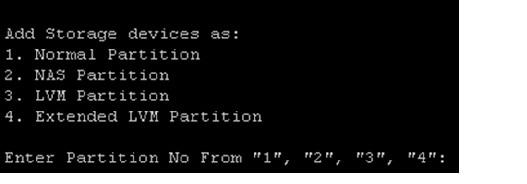
Step 2![]() Select 2, when prompted, to mount the NAS partition (Figure 1).
Select 2, when prompted, to mount the NAS partition (Figure 1).
Step 3![]() Enter the NAS server location.
Enter the NAS server location.
Figure 1 Option to Mount a NAS Partition
Camera Discovery: Manual and Scheduled
IP cameras that have been installed on the network can be discovered and added to Cisco VSM. You can manually trigger discovery, or schedule automatic discovery.
Camera discovery can be performed for a variety of cameras, including cameras that support Bonjour, Onvif cameras, and other cameras.
Auto-configuration can also used to automatically enter basic settings and add the device to Cisco VSM.
See the Cisco Video Surveillance Operations Manager User Guide for more information.
Figure 2 Camera Discovery and AutoConfig Flow
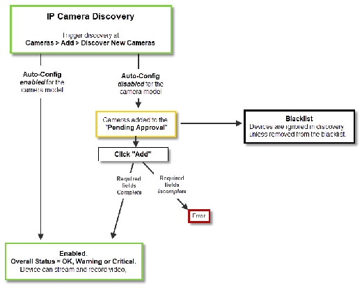

Tip![]() You can also move a discovered camera to the Blacklist to prevent it from being added to Cisco VSM or from being discovered in future discovery actions (Figure 2). Blacklisted Cameras will not get discovered again until removed from the blacklist.
You can also move a discovered camera to the Blacklist to prevent it from being added to Cisco VSM or from being discovered in future discovery actions (Figure 2). Blacklisted Cameras will not get discovered again until removed from the blacklist.
Cameras discovered on the network are added to the Cameras Pending Approval list (Figure 2), allowing you to review the discovered cameras, add additional configuration settings if necessary, and manually approve the camera addition to Cisco VSM.
If Auto-configuration is enabled for a camera model, then the basic configuration and template is automatically applied to the camera, and the camera is added directly to the enabled state (Figure 2). Auto-configuration settings are accessed in System Settings > Auto Provisioning Settings.
Camera discovery is supported on Cisco, Axis, Bosch, Panasonic, IQinVision, Sony, Vivotek and Onvif cameras.
Camera Discovery Process
Camera discovery can be manually triggered or automatically performed according to a schedule.
You can also (optionally) enable the auto-configuration defaults for the camera model to automatically complete the basic camera properties and enable the camera in Cisco VSM.
See the Cisco Video Surveillance Operations Manager User Guide for more information about the following topics procedures.
Add additional camera licenses for non-Cisco cameras, if necessary. |
A license is required for each non-Cisco camera added to your deployment. |
|
Review the overview sections to understand the discovery process. |
See the Cisco Video Surveillance Operations Manager User Guide. |
|
If auto-configuration is enabled for the camera model, the camera will automatically be added to Cisco VSM. |
||
| b. c. – d. – e. – – – f. g. |
||
Wait for the camera to be discovered and be added to the Operations Manager. |
||
Approve cameras that were added to the Cameras Pending Approval list. |
If auto-configuration is not enabled for the camera model, the camera is added to the Cameras Pending Approval list, which allows you to apply additional configurations and approve (add) the camera. a. b. |
|
If auto-configuration was enabled for the camera: a. b. c. |
||
See the Cisco Video Surveillance Operations Manager User Guide. |
 icon flashes when discovery is being performed.
 icon shows the number of discovered cameras. Click the icon to access the devices.
Bookmarks Automatically Deleted with Video
Bookmarks are automatically deleted if the video no longer exists. For example:
- Camera Bookmark—If recording is present, then bookmark will be groomed off based on the maximum retention period of the primary MS or Failover or Redundant or LTS server, plus 1 day.
- Location Bookmark—If a bookmark is applied at a location, the same rule applies based on the longest maximum retention period of the camera’s primary Media Server or Failover / Redundant / LTS server, plus 1 day. Any camera that meets this condition is disassociated from the bookmark. If no camera is associated with the bookmark, then that bookmark is deleted.
- Bookmark with Single Camera Recording Off— If a camera is in “Live only” mode, the bookmark will be groomed off at the end of 1 day. (This is based on the maximum retention period of the primary Media Server or LTS server, plus 1 day. Since the maximum retention period of the primary Media Server or LTS server is 0, grooming occurs at the end of 1 day.)
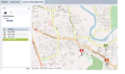
Real-time Camera Status in Maps
The cameras’ state is dynamically updated on maps without needing to reload the maps page (Figure 3).
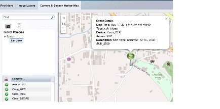
Hover your mouse over a camera to see any new health, security or motion alerts (Figure 4).
Figure 4 View Camera Alerts in Maps
Media Storage Combined into a Single Logical Volume
You can now use the setup_media_storage script to configure a Logical Volume (LVM) that combines multiple partitions into a single logical partition. This allows media to be automatically stored across partitions.
The setup_media_storage script formats the current partition and creates a logical volume. To avoid recording loss, this script must be run when configuring the server and before any cameras are added.
New storage can also be added to an existing LVM using the setup_media_storage script. If new storage is not added to an LVM, it will be added to Cisco VSM as a separate partition.
At least one partition must be configured as LVM. You can then extend that partition by adding more drives to system.
Previously, media partitions were managed separately, such as media1, media2 etc. Media Servers were unable to store recordings from a camera across partitions, so a camera’s video might be groomed from the partition used for that device even if additional capacity was available in another partition. If a partition ran out of storage space, additional storage had to be added as a new media partition.
Improved Video File Storage
By default, all SMD video files are created in 5 minute intervals. Starting in Cisco VSM, however, a new SMB video file is created as soon as an event start/stop is triggered.
This means that event based SMD files can be less than 5 minutes (based on the event duration). This saves disk space, since a 1 minute recording only results in a 1 minute file.
If an event lasts more than 5 minutes, multiple SMDs are created of 5 minutes each. Only the first and last SMD will be less than 5 minutes based on the event start and stop times.
SASD Option to Filter By Active Alerts
In Cisco SASD, the Alert workspace now includes the Active filter which will display only the alerts causing the current problem.
Enhanced Storage Retention Dashboard Status
The Storage Retention Status in the Storage Retention Dashboard now displays a new OK  status icon for additional information, such as when a camera’s recordings are using less storage than estimated.
For example, Cisco VSM estimates the required storage based on the camera bitrate. If Cisco VSM estimates a camera’s recording storage size to be 4GB, but the actual recording storage used is only 2.5GB, the new OK  status icon is displayed. Click this to view additional information in the Retention Status field.
Step 1![]() Log in to the Cisco VSM Operations Manager.
Log in to the Cisco VSM Operations Manager.
Step 3![]() Click Storage Retention Dashboard.
Click Storage Retention Dashboard.
Step 4![]() Select a Media Server and select a camera.
Select a Media Server and select a camera.
Retention Status—Warnings are displayed if the deviation goes above or below the specified percentage. For example:
 —Storage retention is OK.
 —Additional information is available. For example, less space is used than originally estimated.
 —Estimated storage based on streaming is higher than expected.
Next to Reason, click  for more information.
See the Cisco Video Surveillance Operations Manager User Guide for more information.
HA Failover Timeout Configurable Up To 5 Minutes
HA failover from a Media Server to the Failover Server can be configured up to 5 minutes by modifying a text file.
This prevents the HA failover from occurring if the network is going up and down or is unreliable.
See the Cisco Video Surveillance Operations Manager User Guide for more information.
Encrypted Tamper Proof Video Files (CVB format)
CVA clips can be saved as.CVB files that fail to play if they are tampered with.
CVB files are encrypted with a security key. If the file is tampered with, the key cannot be decrypted and playback will fail.
Step 1![]() Select a video pane from the viewing application (such as Cisco SASD or Operations Manager).
Select a video pane from the viewing application (such as Cisco SASD or Operations Manager).
Tip To create a multi-pane clip in the CVA format, press Shift-Click to select multiple concurrent panes, or Ctrl-Click to select individual panes. Individual panes cannot be saved in sync mode.
Step 2![]() In the green seek bar, Ctrl-Click and drag the mouse cursor to create a bookmark span. The bookmark span is shown in orange (Figure 5).
In the green seek bar, Ctrl-Click and drag the mouse cursor to create a bookmark span. The bookmark span is shown in orange (Figure 5).
Step 3![]() Right-click the bookmark and select an option to create a CVA clip (Figure 5).
Right-click the bookmark and select an option to create a CVA clip (Figure 5).
Figure 5 Creating a Video Clip

Step 4![]() (Optional) Revise the start and end date and time (Figure 6). Enter a time between 30 seconds and 24 hours (the range cannot include more than one codec and the start time must be before the end time). Use the Set Duration field to enter a specific length of time for the clip. The duration begins at the beginning bookmark time.
(Optional) Revise the start and end date and time (Figure 6). Enter a time between 30 seconds and 24 hours (the range cannot include more than one codec and the start time must be before the end time). Use the Set Duration field to enter a specific length of time for the clip. The duration begins at the beginning bookmark time.
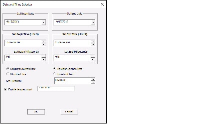
d.![]() (Optional) Select Enable tamper proof and enter a password (Figure 6).
(Optional) Select Enable tamper proof and enter a password (Figure 6).
f.![]() Select a location on a local disk and click Save.
Select a location on a local disk and click Save.
g.![]() Wait for the clip to be generated and downloaded. Video streaming is paused during CVA/CVB clip generation.
Wait for the clip to be generated and downloaded. Video streaming is paused during CVA/CVB clip generation.
h.![]() Play the clip using a video player such as the Cisco Review Player.
Play the clip using a video player such as the Cisco Review Player.
CVA/CVB Clip Passwords Can Be Reset
To reset a forgotten password for a CVB clip, users must belong to a User Group with Reset Clip Password permission.
- The clip’s last modified timestamp is updated when the password is recovered.
- You can only reset the password using the same server where the clip was created. For example, if the clip was created using Operations Manager 'A', you cannot reset the password from Operations Manager 'B' or SASD Federator.
Step 1![]() Right-click the video pane and choose Reset Clip Password.
Right-click the video pane and choose Reset Clip Password.
Step 2![]() Select the select CVB clip from your local drive.
Select the select CVB clip from your local drive.
Step 3![]() Enter and re-enter the new password.
Enter and re-enter the new password.
Step 4![]() Click OK when the confirmation message appears.
Click OK when the confirmation message appears.
Alert Notifications Can Be Sent to WebEx Teams
Health and security alerts can now be sent to WebEx Teams (formerly Spark). This is in addition to email addresses.
Notifications may also include a snapshot of the camera on which the event occurred.
Step 1![]() Log in to the Cisco VSM Operations Manager.
Log in to the Cisco VSM Operations Manager.
Step 2![]() Enter an Authtoken in Cisco VSM to enable communication with WebEx Teams:
Enter an Authtoken in Cisco VSM to enable communication with WebEx Teams:
The Authtoken is a public key provided by your WebEx Teams administrator that allows messages to be securely sent from VSM to WebEx Teams.
a.![]() Go to System Settings > Settings.
Go to System Settings > Settings.
b.![]() In the General tab, enter the Authtoken string in the WebEx Teams User Authtoken field.
In the General tab, enter the Authtoken string in the WebEx Teams User Authtoken field.
Step 3![]() Enter one or more WebEx Teams Rooms that will receive notifications.
Enter one or more WebEx Teams Rooms that will receive notifications.
a.![]() Select Operations > Notification Policies.
Select Operations > Notification Policies.
d.![]() For Security, select By Location or By Camera.
For Security, select By Location or By Camera.
e.![]() Select Send notification on WebEx Teams.
Select Send notification on WebEx Teams.
f.![]() Enter the WebEx Team names, separated by a comma. If the name does not exist it will be created.
Enter the WebEx Team names, separated by a comma. If the name does not exist it will be created.
g.![]() Enter the notification settings for the event type. See the Cisco Video Surveillance Operations Manager User Guide for more information
Enter the notification settings for the event type. See the Cisco Video Surveillance Operations Manager User Guide for more information
i.![]() Create additional entries for additional locations, cameras, and recipients, if necessary.
Create additional entries for additional locations, cameras, and recipients, if necessary.
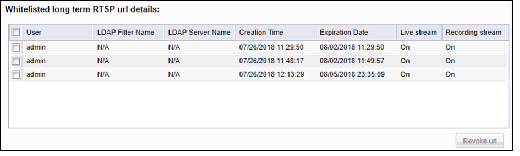
Revoke Longer Duration RTSP URLs
Cisco VSM now provides a way to view details about long duration RTSP URLs, and if necessary, revoke them to disable streaming.
Step 2![]() Select a location and camera.
Select a location and camera.
Step 3![]() Click General > Camera Covert & Whitelisted RTSP URL Details (Figure 7).
Click General > Camera Covert & Whitelisted RTSP URL Details (Figure 7).
The URLs are listed on the right.
Step 4![]() To revoke a URL, select the entry and click Revoke URL.
To revoke a URL, select the entry and click Revoke URL.
Figure 7 Whitelisted RTSP URL Details
Trigger Events and Actions Using External Sensors
3rd party sensors can now be integrated into Cisco VSM to send events that trigger VSM actions, such as recording video from a specific camera. External sensors are a type of device in Cisco VSM, and are managed like cameras.
For example, a door sensors is added to Cisco VSM. When the door is opened, a Cisco VSM event is generated that causes a camera pointed at that door to record video for 5 minutes.
Sensor types, sensor states and other details are defined by the 3rd party product, in cooperation with Cisco Systems. The following examples show sensor integration for the Identiv Connected Physical Access Manager (ICPAM).
Add Sensor Types
For example, add a door sensor type with states “Door Open” and “Door Closed”. These states can be used to trigger Cisco VSM events and actions.
Step 1![]() Go to System Settings > Settings.
Go to System Settings > Settings.
Step 2![]() Click the Sensor System Settings tab.
Click the Sensor System Settings tab.
Step 4![]() Enter the following settings:
Enter the following settings:
- Sensor Type Name—Enter a meaningful name, such as “DoorSensor”.
- Sensor States—Click Add and enter the possible device states used to trigger an event. For example “Door Open, Door Closed”. Separate each state with a comma.
- Change Icon—Click Change Icon to display a custom icon for sensors added to location maps. You can upload new icon images, or select an existing icon image.
- Tags—(Optional) Enter a keyword that assist in a Find.
- Description—(Optional) Enter a meaningful description, such as “Exterior doors that record video when opened”.
Step 5![]() Click Save. The sensor type is shown in the list to the right and can be modified or deleted.
Click Save. The sensor type is shown in the list to the right and can be modified or deleted.
Add Sensor Templates
Templates define the triggers and actions for the sensor types and can be applied to multiple sensors. For example, create a template that will record video whenever a door is opened.
Step 1![]() Go to Sensors > Sensor Templates.
Go to Sensors > Sensor Templates.
Step 3![]() In the General tab, enter the following properties:
In the General tab, enter the following properties:
Step 4![]() Click the Sensor Events tab to define the triggers and actions for the sensor type.
Click the Sensor Events tab to define the triggers and actions for the sensor type.
a.![]() Click Add to create a new Trigger / Action entry.
Click Add to create a new Trigger / Action entry.
–![]() Select a Trigger (such as Sensor Trigger).
Select a Trigger (such as Sensor Trigger).
–![]() Select a Sensor Event Type (such as Door Open or Door Closed).
Select a Sensor Event Type (such as Door Open or Door Closed).
c.![]() Under Resulting Action, select the actions that will occur if an event occurs.
Under Resulting Action, select the actions that will occur if an event occurs.
–![]() One-Time Action: The action that will be triggered, such as Aim Camera or Record for some time.
One-Time Action: The action that will be triggered, such as Aim Camera or Record for some time.
–![]() Select the additional settings for the selected action.
Select the additional settings for the selected action.
Add or Import Sensors
To integrate sensors, add the devices to Cisco VSM and associate them with camera and sensor template. You can add a single sensor or add multiple devices by importing sensors from a CSV file.
Add a Single Sensor
d.![]() Enter the sensor settings as described in Table 2 .
Enter the sensor settings as described in Table 2 .
e.![]() Click Associate Camera(s) with Sensor, select one or more cameras and click OK. Use the filters to narrow the results, or click Search to display all cameras.
Click Associate Camera(s) with Sensor, select one or more cameras and click OK. Use the filters to narrow the results, or click Search to display all cameras.
Step 2![]() Define the triggers and actions for the sensor.
Define the triggers and actions for the sensor.
a.![]() Select the General > Sensor Events tab.
Select the General > Sensor Events tab.
b.![]() Click Set Template to change the template selection.
Click Set Template to change the template selection.
–![]() Select Custom to create event triggers that apply only to the current sensor.
Select Custom to create event triggers that apply only to the current sensor.
–![]() De-select Custom to select an existing template.
De-select Custom to select an existing template.
a.![]() Click Add to create a new Trigger / Action entry.
Click Add to create a new Trigger / Action entry.
–![]() Select a Trigger (such as Sensor Trigger).
Select a Trigger (such as Sensor Trigger).
–![]() Select a Sensor Event Type (such as Door Open or Door Closed).
Select a Sensor Event Type (such as Door Open or Door Closed).
c.![]() Under Resulting Action, select the actions that will occur if an event occurs.
Under Resulting Action, select the actions that will occur if an event occurs.
–![]() One-Time Action: The action that will be triggered, such as Aim Camera or Record for some time.
One-Time Action: The action that will be triggered, such as Aim Camera or Record for some time.
–![]() Select the additional settings for the selected action.
Select the additional settings for the selected action.
Sensor Settings
Import Sensors From a File
Step 1![]() Go to Devices > Sensors.
Go to Devices > Sensors.
Step 2![]() Click Add > Import Sensors From a File.
Click Add > Import Sensors From a File.
Step 3![]() Import Step 1
Import Step 1![]() - Click the Download Sample button for instructions to create an import file in plain text CSV format that contains the sensor device settings.
- Click the Download Sample button for instructions to create an import file in plain text CSV format that contains the sensor device settings.
- Create a file that can be opened and saved using Excel or OpenOffice Calc.
- Enter the sensor settings as described in Table 2 .
Step 4![]() Import Step 2
Import Step 2![]() - File Upload :
- File Upload :
Click Choose to select the CSV file from a local or network disk. Click Upload.
Step 5![]() Import Step 3
Import Step 3![]() - Processing :
- Processing :
Wait for the import process to complete.
Step 6![]() Import Step 5
Import Step 5![]() - Results :
- Results :
Step 7![]() If an error message appears, complete the following troubleshooting steps:
If an error message appears, complete the following troubleshooting steps:
- Click Download Annotated CSV, save the error file and open it in Excel or OpenOffice Calc.
- Correct the annotated errors in the
//Errorrows. - Save the revised file in the
.CSVformat. - Return to Step 2 and re-import the corrected CSV file.
Revised Upgrade Process for Operations Manager HA Servers
Security enhancements in Cisco VSM Release 7.12 require a revised upgrade process for Operations Manager HA Servers.
To upgrade the system software on a Operations Manager server in HA mode, do the following -
Step 1![]() Log into the Operations Manager using the virtual IP address.
Log into the Operations Manager using the virtual IP address.
Step 2![]() Click the pencil icon
Click the pencil icon  in the title bar to place the server in maintenance mode
  .
.
Note The icon is grey  when maintenance mode is on, meaning most user configuration will be rejected (only system tasks and logging are allowed).
Step 3![]() Go to VSOM High Availability tab and click Delete to delete the HA configuration.
Go to VSOM High Availability tab and click Delete to delete the HA configuration.
Step 4![]() Upgrade the Master Log in to the Peer Operations Manager server:
Upgrade the Master Log in to the Peer Operations Manager server:
a.![]() Log in to the Master Operations Manager using it’s direct IP address.
Log in to the Master Operations Manager using it’s direct IP address.
b.![]() Upload the upgrade.zip file.
Upload the upgrade.zip file.
c.![]() Upgrade the Master Operations Manager server.
Upgrade the Master Operations Manager server.
Step 5![]() Upgrade the Peer Operations Manager server, upload the.zip file and upgrade the Peer server.
Upgrade the Peer Operations Manager server, upload the.zip file and upgrade the Peer server.
Step 6![]() Upgrade the Split Brain Media Servers.
Upgrade the Split Brain Media Servers.
Step 7![]() After the Master, Peer and Split Brain Media Servers are upgraded, re-establish HA.
After the Master, Peer and Split Brain Media Servers are upgraded, re-establish HA.
Getting Started
Cisco VSM Release 7.12 is pre-installed on new servers, can be installed as a virtual machine, or used to upgrade an existing deployment.
Release 7.12 is pre-installed in new installations on the Cisco Connected Safety and Security UCS Platform Series servers: |
See Cisco Connected Safety and Security UCS Platform Series Servers for more information. |
|
Direct upgrades can be performed from the previous 3 releases. Older releases require alternative methods. Upgrades can be performed on Cisco VSM virtual machines (VMs) and on Cisco Video Surveillance servers. |
||
An.OVA template file is used to install a new virtual machine (VM) instance of the server. |
After an.OVA virtual machine is installed, you can use the Cisco VSM Management Console to perform future upgrades of the system software. See Cisco Video Surveillance Virtual Machine Deployment and Recovery Guide for UCS Platforms for more information. |
See the following for more information:
- Cisco Video Surveillance Manager: Install and Upgrade Guide
- Cisco Connected Safety and Security UCS Platform Series Servers
- Upgrading from Previous Cisco VSM Releases
- Recovery/Factory Image
Cisco Connected Safety and Security UCS Platform Series Servers
Cisco VSM Release 7.12 is pre-installed on new installations of the Cisco Connected Safety and Security UCS Platform Series when ordered with the Cisco VSM software installed.
- Cisco CSS UCS Server User Guide — supported features, physical installation and setup instructions
- Release Notes for the Cisco CSS UCS Servers
- After the server appliance is installed, see the Cisco Video Surveillance Manager: Install and Upgrade Guide to perform the initial Cisco VSM setup.
- For additional server hardware documentation, see the Cisco UCS C-Series Server Documentation (Roadmap).
Upgrading from Previous Cisco VSM Releases
For complete instructions, see the Cisco Video Surveillance Manager: Install and Upgrade Guide.
The following table describes the upgrade methods based on how old your server’s current release is.
Directly upgrade the system software on the server using a Upgrades can be performed on Cisco VSM virtual machines (VMs) and on Cisco Video Surveillance servers. |
||
Backup and restore to a new server For example, backup the configuration and data from a release 7.9 server and restore it to a new release 7.12 server. Note Only backups that include configuration + historical data are supported for upgrades. Configuration-only backups are not supported and will cause a config mismatch in cameras. |
Cisco Video Surveillance Manager: Install and Upgrade Guide |
|
For older releases, first upgrade to 7.6 then upgrade to latest version. |
- Release 7.0 was pre-installed on the Cisco Multiservices Platform (Cisco MSP) servers, including the CPS-MSP-1RU-K9 and CPS-MSP-2RU-K9.
- Release 7.2 to Release 7.7 was pre-installed on the CPS-UCS-1RU-K9 and CPS-UCS-2RU-K9 Cisco CSS UCS series servers.
–![]() The CIVS platform is not supported and cannot be upgraded to VSM 7.7 or later.
The CIVS platform is not supported and cannot be upgraded to VSM 7.7 or later.
–![]() CPS-UCSM4-1RU-K9 / Cisco CPS UCSM4 2RU
CPS-UCSM4-1RU-K9 / Cisco CPS UCSM4 2RU
–![]() KIN-UCSM5-1RU-K9 / KIN-UCSM5-2RU-K9
KIN-UCSM5-1RU-K9 / KIN-UCSM5-2RU-K9
Note![]() Virtual Machine (VM) installations can also be upgraded using the Cisco VSM Management Console. Upgrades are supported from release 7.8 or higher on the RHEL6 operating system. See Cisco Video Surveillance Virtual Machine Deployment and Recovery Guide for UCS Platforms for more information.
Virtual Machine (VM) installations can also be upgraded using the Cisco VSM Management Console. Upgrades are supported from release 7.8 or higher on the RHEL6 operating system. See Cisco Video Surveillance Virtual Machine Deployment and Recovery Guide for UCS Platforms for more information.
Recovery/Factory Image
You can also create a bootable USB flash drive that can be used to recover an installation or perform a a factory installation of Cisco VSM Release 7.12 on a supported physical server that shipped with Cisco VSM Release 7.12 pre-installed. This includes CPS-UCSM5-1RU-K9 and CPS-UCSM5-2RU-K9.
For more information, see Cisco Video Surveillance Manager: Install and Upgrade Guide
Released Versions
Cisco VSM Release 7.12 is released with Cisco_VSM-7.12.0-194i. The component package versions are:
- Cisco_VSMUpgrade-7.12.0-112d.i686
- Cisco_MetaDataService-7.12.0-112d.i686
- Cisco_VSF-7.12.0-185.noarch
- Cisco_VSBase-7.12.0-112d.i686
- Cisco_AMQBroker-7.12.0-1.noarch
- Cisco_VSDrivers-7.12.0-112d.i686
- Cisco_VSOM-7.12.0-185.x86_64
- Cisco_DashCast-7.12.0-112d.i686
- Cisco_VSMS-7.12.0-112d.i686
- Cisco_SASD-7.12.0-75.noarch
- Cisco_CDAF-7.12.0-185.noarch
- Cisco_VSRecorder-7.12.0-112d.i686
- Cisco_MPClient-7.12.0-47.noarch
- Cisco_GeoServer-7.12.0-1.noarch
- Cisco_Tomcat-7.0.90-1.el6.noarch
- Cisco_VSTools-7.12.0-112d.i686
Supported Devices
The following sections provide information about the devices that this version of Cisco VSM supports:
- Supported Devices: Cisco
- Supported Devices: Arecont
- Supported Devices: Axis
- Supported Devices: IQinVision
- Supported Devices: Mobotix
- Supported Devices: Panasonic
- Supported Devices: Pelco
- Supported Devices: Sony
- Supported Devices: Vivotek
- Supported Devices: Generic IP Cameras
- Supported Devices: Analog Cameras
- Device Models Validated in Cisco VSM as Generic IP Cameras
Supported Devices: Cisco
Table 5 through Table 11 provide information about Cisco devices supported in this release:
- Cisco 2400/2500, 2600, 2800, and 2900 Series Basic functionality such as streaming and recording is supported. Any features that require a firmware upgrade are not supported.
- Cisco 3000 Series
- Cisco 4000 Series and 5000 Series Basic functionality such as streaming and recording is supported. Any features that require a firmware upgrade are not supported.
- Cisco 6000 Series
- Cisco 7000 Series
- Cisco 8000 Series
- Cisco CIVS-SENC-4P and CIVS-SENC-8P
|
FW Version for Release 7.12 Compatibility
1
|
||||||||||
|---|---|---|---|---|---|---|---|---|---|---|
|
FW Version for Release 7.12 Compatibility
2
|
||||||||||
|---|---|---|---|---|---|---|---|---|---|---|
|
FW Version for Release 7.12 Compatibility
3
|
||||||||||
|---|---|---|---|---|---|---|---|---|---|---|
|
FW Version for Release 7.12 Compatibility
4
|
||||||||||
|---|---|---|---|---|---|---|---|---|---|---|
|
FW Version for Release 7.12 Compatibility
5
|
||||||||||
|---|---|---|---|---|---|---|---|---|---|---|
|
FW Version for Release 7.12 Compatibility
9
|
||||||||||
|---|---|---|---|---|---|---|---|---|---|---|
Additional Notes on Cisco Devices
- Cisco 4500 and 4500E support video analytics.
- Redundancy is supported for all Cisco devices some exceptions for the 2400, 2500, 2900 and 5000 series. The 2400, 2500, 2900 and 5000 series do not support sending events to the redundant server such motion detection and contact closure events.
- Cisco 5000 series does not support motion detection at video bit-rates above 4,000 (4 Mbps). The “H” video preset in Templates has been chosen to not exceed this, so motion detection will work.
- The Cisco 5000 and 2900 camera series do not allow changes to the authentication settings (username/password) or networking settings (DHCP/Static, DNS, etc.) through Cisco VSM. These values can only be changed using the camera web interfaces.
- Focus, Auto Focus and Zoom support are not available for Cisco 6000P, 3421V, 3520, 3530, 3535, and 3050 camera models.
- When Cisco VSM manages a Cisco 6930, 2830, or 2835 camera, it automatically enables the HTTP protocol on the camera and uses this protocol to send PTZ commands to the camera. Other configuration commands continue to use the HTTPS protocol.
- The Cisco 2830, 2835, 3000 series, 6000 series and 7030 cameras now support MJPEG primary streams.
- Cisco 3421V and 6050 cameras do not support Contact Closure, Cisco 7030 camera supports 3 input ports. All other Cisco 3000, 6000, 8000 series cameras support 1 input port.
- In PTZ Tour Configuration, the configured transition time configured includes the time that it takes the camera to move from the one preset position to the next preset position in addition to the time that the camera is expected to stay in the preset position. If the transition time is configured to a value that is less than the time that it takes the camera to move from one preset position to the next, the camera moves between the first and second presets positions only, instead of touring between all preset positions that are configured in the tour.
- The minimum firmware version required to support camera applications is 2.5.0-10.
- The minimum firmware version required to support connected edge storage is 2.0.
Supported Devices: Arecont
Table 12 provides information about Arecont devices that this Cisco VSM release supports.
Additional Notes on Arecont Devices
- AV20185, AV20365, AV12186, AV8365 and AV8185 are 4-channel IP cameras. In order to support multiple video channels from a single device, Cisco VSM 7 models these devices as “Encoders”.
- Arecont devices have not yet been qualified to support redundancy in Cisco VSM 7.
- Secondary streams are not supported in H, M, L template settings for Arecont Devices. However secondary stream can be configured using Custom templates.
- Arecont cameras divide the Maximum FPS the camera supports by the number of streams. This could result in lower FPS when both primary and secondary streams are configured for these cameras.
- Arecont AV10XX5, AV5115, AV2115 support VBR and multicast streaming.
- There is a restriction with motion detection for Arecont multi-sensor cameras. False motion events are generated if both half and full resolution size images are requested simultaneously using Cisco VSM or Arecont Camera Web Interface or a third party Media Player.
Supported Devices: Axis
Table 13 , Table 14 , and Table 15 provide information about Axis devices supported in this release.
|
Version
10
|
||||||||||
|
Version
11
|
||||||||||
Table 15 provides information about additional Axis devices that this Cisco VSM release supports.
Additional Notes on Axis Devices
- Axis P3301 IP camera and Q7401, Q7404, and Q7406 encoders have been qualified to support redundancy in Cisco VSM 7.0.1.
- Axis 233D supports contact closure configuration and events.
- Support for 0.1fps MJPEG stream for all supported Axis models.
The following table documents the various Field-Of-Views supported for the Axis M3007 panoramic cameras and support for PTZ and Motion Detection for these Field-Of-Views.
The Axis M3007 camera allows the user to configure various mounting options directly in the camera web interface that affects the possible values for Field-Of-Views that can be configured on the camera. The table below provides this mapping:
Supported Devices: IQinVision
Table 18 provides information about IQinVision devices that this Cisco VSM release supports.
Supported Devices: Mobotix
Table 19 provides information about Mobotix devices that this Cisco VSM release supports.
Supported Devices: Panasonic
Table 20 provides information about Panasonic devices that this Cisco VSM release supports.
Additional Notes on Panasonic Devices
- Panasonic devices have not yet been qualified to support redundancy in Cisco VSM 7.
- Only same field of views can be configured on primary and secondary streams on Panasonic cameras SW458/SF438.
- The following table documents the various Field-Of-Views supported for the Panasonic SF 458 and SF 438 panoramic cameras and support for PTZ and Motion Detection for these Field-Of-Views.
Supported Devices: Pelco
Table 22 provides information about Pelco devices that this release supports.
Additional Notes on Pelco Devices
- Pelco devices have not yet been qualified to support Redundancy in Cisco VSM 7.
- Audio volume controls are not supported for NET540XT
- For Pelco NET540xT PTZ to work, the analog camera should be chosen as Pelco Analog Camera (pelco_sarix) in Operations Manager and not as Pelco D.
- The user needs to directly configure the Serial protocol on the Pelco NET540XT encoder outside of Cisco VSM.
- The Pelco Spectra IV TXB-N (H.264 capable model) run Pelco Sarix firmware and can be supported in Cisco VSM as a Pelco Sarix Generic IP camera (additional details in the Generic IP camera section).
Supported Devices: Sony
Table 23 provides information about Sony devices that this release supports.
Additional Notes on Sony Devices
- Sony devices have not yet been qualified to support redundancy in Cisco VSM 7.
- These Sony devices do not support motion detection with the H.264 media type.
- The Sony SNC-RX5x0 cameras stop streaming video when the Object Detection window is opened in the camera’s web interface.
- For Sony HM662 Panoramic camera, only the 360 degree view is supported. De-warped views are not supported.
Supported Devices: Vivotek
Table 24 provides information about Vivotek devices that this release supports.
Supported Devices: Generic IP Cameras
Cisco VSM Release 7.12 provides the following device drivers to support IP cameras from various vendors. The functionality they support will depend on the particular device that they are used with. They are intended to provide a quick and easy way to support devices for which there isn’t yet a specific driver available for Cisco VSM. Since these drivers may not be tested with a specific device, some issues may be encountered. When using these drivers with a device, failover and redundancy are not supported.
Note![]() The vendor specific generic driver should always be used before a non-vendor specific driver such as ONVIF.
The vendor specific generic driver should always be used before a non-vendor specific driver such as ONVIF.
|
Motion Detection
14
|
||||||||
|---|---|---|---|---|---|---|---|---|
- Supports only IP Cameras, no support for Encoders
- No contact closure support
- Multicast streaming is supported only for the primary stream
- Multicast port must be an even number within the range 16000:19999
- Audio Multicast issues are observed on most of the ONVIF cameras. Hence do not enable audio when multicast is enabled for video.
- Capture Mode on the camera cannot be changed using ONVIF APIs. So, it is assumed that the camera is in the desired capture mode before adding it to VSOM using ONVIF
- This ONVIF driver has been tested with a limited number of camera models from Axis, Sony, Panasonic, Bosch, Pelco, Samsung, J2000IP, Hikvision and Cohu. We have found that these cameras have some variations in how they have implemented the ONVIF specification. Hence there may be compatibility issues when using this ONVIF driver with a particular device that is ONVIF compliant.
- Some of the known caveats are listed below:
- ONVIF user account—Some Axis cameras require a special ONVIF user account, which can be created on the camera's web interface before adding an AXIS ONVIF camera to the VSOM. This page is at Setup --> System Options --> Security --> ONVIF --> Add
- Camera and VSMS (Media Server) Time Synchronization—ONVIF camera and VSMS server to which ONVIF camera is being added should have their time synchronized ideally using NTP.
- Codec Change through VSOM—Hikvision camera requires a reboot after the codec is changed from VSOM.
- The Minimum Firmware Version of Hikvision cameras supported is V5.3.0, to be added as ONVIF camera in Cisco VSM.
- Megapixel Mode setting on the camera SND-7080
- To support the resolutions (1600*1200) and (2048*1536), change the Megapixel Mode to 3-Megapixel in the following page on the camera browser: Settings -> Audio & Video -> video profile -> Megapixel mode
- Enable Authentication on the camera before adding it to VSOM In the camera browser, go to Camera Setup -> Configuration -> User Settings. Select User and enable “Require Password” field.
- Media Transport Type— Only UDP is supported. Streaming fails if TCP is selected.
- Unsupported Resolutions —Streaming fails for the resolutions 176*144, 176*120, 160*120
- Codec Change through VSOM— Switching from H264 to JPEG or vice-versa requires a camera reboot. And camera needs to be deleted and added in VSOM after camera is up.
- Support for Audio— Camera does not support ONVIF Audio
- Frame rate— Only Framerate 30 is supported
- Dual Streaming— Secondary configuration overwrites the primary configuration. So, dual streaming is not supported on Bosch cameras using ONVIF.
- Capture Mode Setting— If the camera is added in VSOM using Multicast, changing the capture mode on the camera browser manually causes the streaming to fail. After this, only the unicast streaming works
- User Authentication— User Authentication should be enabled in the camera browser as follows - Setup -> User mng -> User auth. Choose ON for User auth.
- Media Transport Type— Only UDP is supported. Streaming fails if TCP is selected
- Support for Audio— Camera does not support ONVIF Audio
- Set Configuration Issues — Camera returns success even if one or more of the parameters are not valid for that camera/video stream. ONVIF profile gets updated with values but Camera still uses the previous correct value. Recommend to configure only the values as allowed in the camera browser.
- Support for Password change on the camera— Camera does not support password change for the administrator users using ONVIF API.
Supported Devices: Analog Cameras
This Cisco VSM release provides support for the following analog cameras.
Device Models Validated in Cisco VSM as Generic IP Cameras
The camera models listed in Table 27 have been tested with VSM Release 7.12 as generic IP cameras.
Clipping Support By Application
You can create and view video clips using the following Cisco VSM applications:
Note![]() When converting a virtual clip to an MP4 file, only the entire duration of the virtual clip can be saved, not a segment.
When converting a virtual clip to an MP4 file, only the entire duration of the virtual clip can be saved, not a segment.
Obtaining and Installing Licenses
To install a license, purchase the license and obtain the license file, then upload the file to the Operations Manager.
Table 29 lists the part numbers for the Cisco VSM licenses. Multiple camera and VSMS licenses can be included in a single license file. For example, a single license file might include support for 25 additional cameras and two additional VSMS devices.
- A license for 10,000 Cisco cameras is included by default (you do not need to purchase and install an additional license for Cisco cameras).
- You can add 1 Media Server and 10 non-Cisco cameras without a license for initial setup purposes only. This feature is removed when you add any permanent license.
Step 1![]() Purchase additional licenses:
Purchase additional licenses:
a.![]() Determine the part number for the license you want to purchase (see Table 29 ).
Determine the part number for the license you want to purchase (see Table 29 ).
b.![]() Purchase the license by contacting your Cisco sales representative or any Cisco reseller. For more information, visit http://www.cisco.com/en/US/ordering/index.shtml.
Purchase the license by contacting your Cisco sales representative or any Cisco reseller. For more information, visit http://www.cisco.com/en/US/ordering/index.shtml.
c.![]() When the purchase is complete, you are issued a Product Authorization Key (PAK) in paper form, or in an e-mail message.
When the purchase is complete, you are issued a Product Authorization Key (PAK) in paper form, or in an e-mail message.
Step 2![]() Obtain the license file:
Obtain the license file:
a.![]() Locate the Product Authorization Key (PAK) that was created with the purchase.
Locate the Product Authorization Key (PAK) that was created with the purchase.
b.![]() In a web browser, open the Cisco Product License Registration web page.
In a web browser, open the Cisco Product License Registration web page.
http://www.cisco.com/go/license/
c.![]() Follow the on-screen instructions to complete the form and enter the Product Authorization Key (PAK). When you are done, a license file with the extension
Follow the on-screen instructions to complete the form and enter the Product Authorization Key (PAK). When you are done, a license file with the extension.lic is sent to your e-mail address.
d.![]() Transfer the file to the drive of the PC used for the configuration.
Transfer the file to the drive of the PC used for the configuration.
Step 3![]() Install the license file in Cisco VSM:
Install the license file in Cisco VSM:
a.![]() Log in to the Operations Manager.
Log in to the Operations Manager.
b.![]() Select System Settings > Software Licensing.
Select System Settings > Software Licensing.
c.![]() Click Add and select the license file located on your local drive.
Click Add and select the license file located on your local drive.
d.![]() Click Save to install the file and activate the additional capacity.
Click Save to install the file and activate the additional capacity.
The additional capacity is available immediately. You do not need to restart the server or take additional steps.
See the Cisco Video Surveillance Operations Manager User Guide for more information.
Understanding the Cisco VSM Software Types
Table 30 describes the different types of software and firmware that are installed on servers, cameras, and encoders.
System software denotes the Cisco VSM software, including Media Server, Operations Manager, Cisco VSM Management Console, Safety and Security Desktop and Multipane clients. All servers running the Operations Manager and associated Media Server services must run the same software version. Use the Operations Manager to update the System Software on all servers (such as Media Servers) associated with the Operations Manager. See the Cisco Video Surveillance Operations Manager User Guide for instructions.
|
|
OVF template files are used to install the system software as a virtual machine (VM) on a supported Cisco Unified Computing System (UCS) platform.
|
|
Use the USB Recovery Disk image to create a Cisco VSM 7 Recovery Flash Drive (for example, on a USB stick). The recovery disk can be used do the following:
See the Cisco CSS UCS Server User Guide for more information. |
|
Device firmware is provided by the device manufacturer. The firmware for Cisco devices can be upgraded using Operations Manager. Firmware for other manufacturers is upgraded using a direct connection. See the “Upgrading Camera and Encoder Driver Firmware” section of the Cisco Video Surveillance Operations Manager User Guide for instructions to upgrade Cisco device firmware, or refer to the device documentation. |
|
Device driver packs are the software packages used by Media Servers and the Operations Manager to interoperate with video devices, such as cameras. Driver packs are included with the Cisco VSM software, or may be added to a server at a later time to add support for new devices or features.
– – Note We strongly recommend upgrading driver packs using the Operations Manager interface (see the “Driver Pack Management” section of the Cisco Video Surveillance Operations Manager User Guide). This allows you to upgrade multiple servers at once. |
|
Language packs can be added to display the Cisco VSM user interfaces in non-English languages. Language packs are added using the Operations Manager (release 7.6 and higher). See the Cisco Video Surveillance Operations Manager User Guide for instructions. |
Obtaining Cisco VSM Software
Complete the following procedure to obtain software and other information for the Cisco VSM products and components:
Step 1![]() Go to the Cisco Video Surveillance Manager product page.
Go to the Cisco Video Surveillance Manager product page.
Step 2![]() Click Download Software.
Click Download Software.
Step 3![]() Select a product category. For example:
Select a product category. For example:
- Video Surveillance Device Driver
- Video Surveillance Manager Stand-alone Tools
- Video Surveillance Media Server Software (including system software)
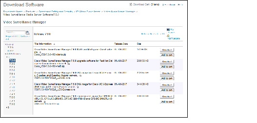
Step 4![]() Select the release for your server, device, or deployment (Figure 8).
Select the release for your server, device, or deployment (Figure 8).
Step 5![]() Click Download or Add to Cart and follow the onscreen instructions.
Click Download or Add to Cart and follow the onscreen instructions.
Figure 8 Download Software Page
You can also navigate the Cisco Physical Security product pages to download software updates and other information:
Step 1![]() Go to the following URL.
Go to the following URL.
http://www.cisco.com/go/physicalsecurity
Step 2![]() Click View All Physical Security Products.
Click View All Physical Security Products.
Step 3![]() Click IP Video Surveillance.
Click IP Video Surveillance.
Step 4![]() Click Cisco Video Surveillance Manager.
Click Cisco Video Surveillance Manager.
Step 5![]() Click Download Software for this Product.
Click Download Software for this Product.
Step 6![]() Click a Software Type and follow the onscreen instructions.
Click a Software Type and follow the onscreen instructions.
For example: Video Surveillance Media Server Software (Figure 8).
Step 7![]() Select the release for your server, device, or deployment.
Select the release for your server, device, or deployment.
Step 8![]() Click Download or Add to Cart and follow the onscreen instructions.
Click Download or Add to Cart and follow the onscreen instructions.
Caveats
This section includes the following topics:
Using the Software Bug Search Tool
You can use the Bug Search Tool to find information about most caveats for Cisco VSM releases, including a description of the problems and available workarounds. The Bug Search Tool lists both open and resolved caveats.
To access Bug Search Tool, you need the following items:
To use the Software Bug Search Tool, follow these steps:
Step 1![]() To access the Bug Search Tool, go to https://tools.cisco.com/bugsearch/
To access the Bug Search Tool, go to https://tools.cisco.com/bugsearch/
Step 2![]() Log in with your Cisco.com user ID and password.
Log in with your Cisco.com user ID and password.
Step 3![]() To look for information about a specific problem, enter the bug ID number in the Search for field.
To look for information about a specific problem, enter the bug ID number in the Search for field.
Step 4![]() For more information, go to the Bug Search interactive tour.
For more information, go to the Bug Search interactive tour.
Open Caveats
Table 31 lists caveats that are open in this release.
Resolved Caveats
Table 32 lists caveats that are resolved in this release.
Related Documentation
See the following locations for the most current information and documentation:
Cisco Video Surveillance 7 Documentation Roadmap
Descriptions and links to Cisco Video Surveillance documentation, server and storage platform documentation, and other related documentation.
http://www.cisco.com/go/physicalsecurity/vsm/roadmap
Cisco Physical Security Product Information:
www.cisco.com/go/physicalsecurity/
Cisco Video Surveillance Manager Documentation Website
www.cisco.com/go/physicalsecurity/vsm/docs
Cisco and the Cisco logo are trademarks or registered trademarks of Cisco and/or its affiliates in the U.S. and other countries. To view a list of Cisco trademarks, go to this URL: www.cisco.com/go/trademarks. Third-party trademarks mentioned are the property of their respective owners. The use of the word partner does not imply a partnership relationship between Cisco and any other company. (1721R)
Any Internet Protocol (IP) addresses and phone numbers used in this document are not intended to be actual addresses and phone numbers. Any examples, command display output, network topology diagrams, and other figures included in the document are shown for illustrative purposes only. Any use of actual IP addresses or phone numbers in illustrative content is unintentional and coincidental.
 Feedback
Contact Cisco
- Open a Support Case

- (Requires a Cisco Service Contract)