Cisco Video Surveillance 8400 IP Camera Reference Guide, Release 1.0.0
Bias-Free Language
The documentation set for this product strives to use bias-free language. For the purposes of this documentation set, bias-free is defined as language that does not imply discrimination based on age, disability, gender, racial identity, ethnic identity, sexual orientation, socioeconomic status, and intersectionality. Exceptions may be present in the documentation due to language that is hardcoded in the user interfaces of the product software, language used based on RFP documentation, or language that is used by a referenced third-party product. Learn more about how Cisco is using Inclusive Language.
- Updated:
- April 9, 2020
Chapter: Getting Started
Getting Started
This chapter provides information about getting started with and understanding the IP camera. It includes the following sections:
Overview
The Cisco Video Surveillance 8400 IP Cameras is a high-definition, full-functioned video endpoint with industry-leading image quality and processing power. The camera is capable of 5MP resolution at 30 frames per second (fps) while optimizing network usage with either H.264, H.235, or MJPEG compression. Contact closures and two-way audio allow integration with microphones, speakers, and access control systems. With its open, standards-based design, the camera provides an ideal platform for integration and operation as independent devices or as part of a Cisco video surveillance network.
Key features and benefits of the camera include:
- True high-definition video—The camera streams crisp and clear 5MP video at 30 fps while maintaining low network bandwidth.
- Quad streaming—The camera can stream H.264, H.265, and MJPEG video simultaneously. Each video stream can be configured with individual resolution, quality, and frame-rate settings.
- Day/night operation—The camera provides true day/night functionality, and includes an infrared (IR) filter that automatically switches to night mode in low-light scenes. This function can be set to manual, automatic, or scheduled control.
- Flexible power option—The camera supports Power over Ethernet (PoE) 802.3at or 12 VDC.
- Mounting options—The camera can be installed to either a ceiling or wall.
- Motion Detection and Event notification—The camera can examine designated areas for activity and notify users or other applications when it detects activity that exceeds a predefined sensitivity and threshold. The camera also provides one digital input and one digital output that can be used to initiate specific actions when an alarm is detected.
The camera is able to operate in low temperature environments. However, when starting the camera in a very low temperature condition, for example, –40ºC, the embedded heater may take half an hour to warm up the camera. When the temperature within the canister reaches –10ºC, the camera automatically starts.
Physical Description
Front Panel
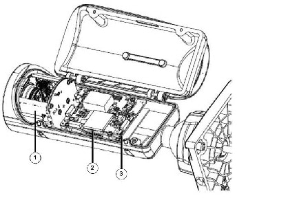
Figure 1-1 shows the front panel of the Cisco Video Surveillance 8400 IP Camera.
Figure 1-1 Cisco Video Surveillance 8400 IP Camera Front Panel
|
|
|
|
|
|
|
|
This come with an embedded heater and requires an 802.3at PoE switch.
DI/DO Diagram
The following figure provides the DI/DO diagram:
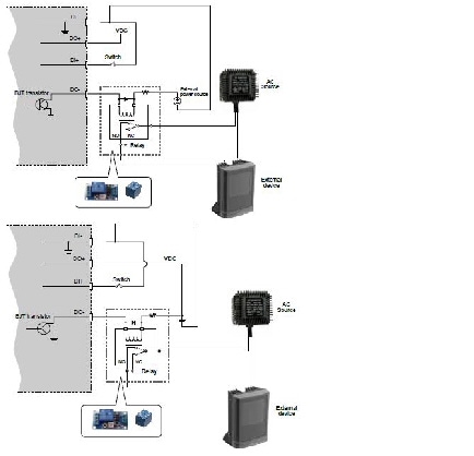
- The DO+ pin provides output of 12V, and the max. load is 50mA.
- The max. voltage for DO- pins is 80VDC (external power). In order to control AC devices, the above diagram can be taken in consideration. The diagram uses a relay to control the ON/OFF condition of the AC device.
- An external relay can be triggered by using DO+ or by an external power source, depending on the type of relay you use.
- In case of using an individual relay (instead of using a relay module), for protection against voltage or current spikes, a transient voltage suppression diode must be connected in parallel with the inductive load.
Power Adapters
This product is intended to be supplied by a |
Hardware Installation
To perform the hardware installation of the Cisco Video Surveillance 8400 IP Camera, follow these steps:
Step 1![]() Make a note of the MAC address of the camera.
Make a note of the MAC address of the camera.
The MAC address is printed on the label that is attached to the camera.
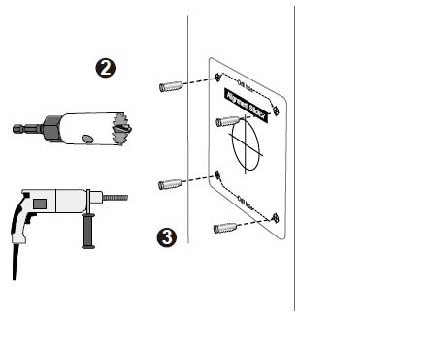
Step 2![]() Attach the included alignment sticker to a preferred location.
Attach the included alignment sticker to a preferred location.
Step 3![]() Drill holes for mounting screws and a cabling hole.
Drill holes for mounting screws and a cabling hole.
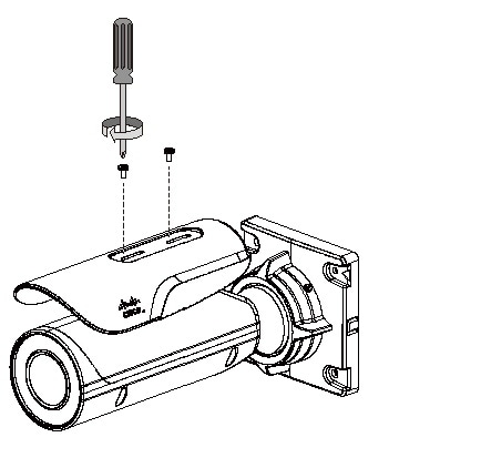
Step 4![]() Loosen the anti-tamper screws to open the top cover.
Loosen the anti-tamper screws to open the top cover.
Step 5![]() Insert an SD card (user-supplied).
Insert an SD card (user-supplied).
Step 6![]() Replace the desiccant bag whenever you open the top cover. This ensures the components are free from the moisture
Replace the desiccant bag whenever you open the top cover. This ensures the components are free from the moisture
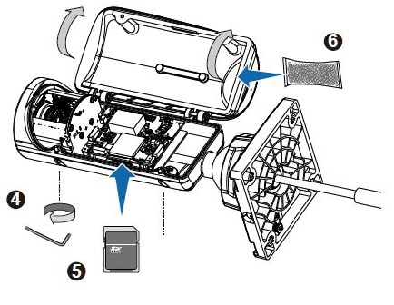
Step 7![]() Install the sun shield.
Install the sun shield.
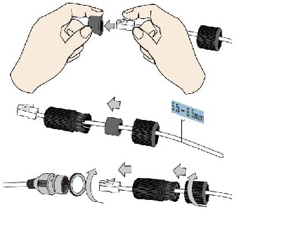
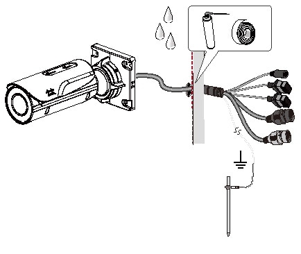
Step 8![]() When connecting the LAN cable, use the cable housing to make sure the connections are waterproof.
When connecting the LAN cable, use the cable housing to make sure the connections are waterproof.
a.![]() Pass the cable through the seal dome, and squeeze the rubber seal through an RJ45 connector.
Pass the cable through the seal dome, and squeeze the rubber seal through an RJ45 connector.
b.![]() You can then pass the cable through the cable gland body.
You can then pass the cable through the cable gland body.
c.![]() Connect the Ethernet cable to the camera RJ45 connector with a seal ring. Fasten up these components. Make sure enough pressure is exerted on the rubber seal. 5.5 ~ 6.5mm.
Connect the Ethernet cable to the camera RJ45 connector with a seal ring. Fasten up these components. Make sure enough pressure is exerted on the rubber seal. 5.5 ~ 6.5mm.
d.![]() Connect the other interfaces, such as I/O wires.
Connect the other interfaces, such as I/O wires.
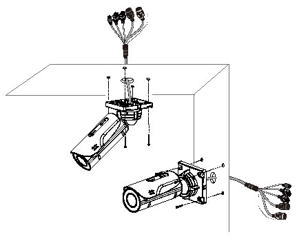
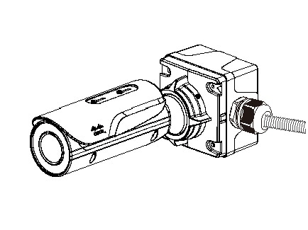
Step 9![]() Secure the camera to a wall or ceiling.
Secure the camera to a wall or ceiling.
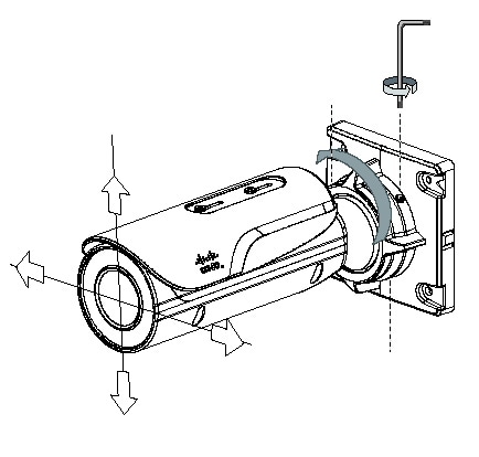
Step 10![]() Adjust the shooting direction by loosening the hex and anti-tamper screws on the fastening ring. Aim the camera at the area of your interest. Tighten the fastening ring when done with the adjustment.
Adjust the shooting direction by loosening the hex and anti-tamper screws on the fastening ring. Aim the camera at the area of your interest. Tighten the fastening ring when done with the adjustment.
Step 11![]() If your cables pass through a hole on a wall or ceiling, make sure the passage is waterproof using sealant foam, heat shrink tubing, or putties. Make sure the interfaces, for example, DC connectors and terminal connectors, if unused, are also wrapped up using waterproof putties.
If your cables pass through a hole on a wall or ceiling, make sure the passage is waterproof using sealant foam, heat shrink tubing, or putties. Make sure the interfaces, for example, DC connectors and terminal connectors, if unused, are also wrapped up using waterproof putties.
Connect the ground wire to a metal conduit or other ground path.
You can also purchase the CIVS-8KA-JBOX junction box to place all cabling connections within the protection of the box.
Step 12![]() With a live view displayed on your laptop, adjust the zoom and focus to obtain an optimal image. Check the live view to ensure the image is in focus.
With a live view displayed on your laptop, adjust the zoom and focus to obtain an optimal image. Check the live view to ensure the image is in focus.
LED Definitions
Table 1-1 describes the LEDs on the Cisco Video Surveillance IP Camera.
Hardware Reset
The recessed button (see Figure 1-1) is used to reset the system or restore the factory default settings. Sometimes resetting the system can return the camera to normal operation. If the system problems remain after reset, restore the factory settings and install again.
MicroSD/SDHC/SDXC Card Capacity
The camera is compliant with SD/SDHC/SDXC 16GB / 8GB / 32GB / 64GB and other preceding standard SD cards.
Network Deployment
The following sections provide information about deploying the camera on a network:
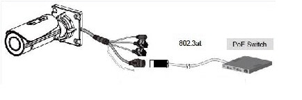
General Connection (PoE)
The camera is PoE-compliant, allowing transmission of power and data via a single Ethernet cable. Figure 1-3 illustrates how to connect the camera to a PoE-enabled switch via an Ethernet cable.
Figure 1-3 Connecting the Camera to a PoE-Enabled Switch
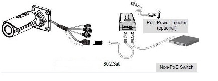
Use a PoE power injector (optional) to connect between the camera and a non-PoE switch, as shown in Figure 1-4.
Figure 1-4 Connecting the Camera to a Non-PoE Switch

Note ●![]() The camera is only to be connected to PoE networks without routing to outside plants.
The camera is only to be connected to PoE networks without routing to outside plants.
Network Connection
Internet Connection via a Router
Step 1![]() Connect your camera behind a router, the Internet environment is illustrated in Figure 1-5.
Connect your camera behind a router, the Internet environment is illustrated in Figure 1-5.
Figure 1-5 Connecting the Camera Via a Router
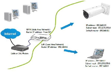
Step 2![]() In this case, if the Local Area Network (LAN) IP address of your camera is 192.168.0.3, forward the following ports for the camera on the router.:
In this case, if the Local Area Network (LAN) IP address of your camera is 192.168.0.3, forward the following ports for the camera on the router.:
If you have changed the port numbers on the Network page, open the ports accordingly on your router. For information about how to forward ports on the router, see your router documentation.
Step 3![]() Find out the public IP address of your router provided by your Internet Service Provider (ISP).
Find out the public IP address of your router provided by your Internet Service Provider (ISP).
Use the public IP and the secondary HTTP port to access the camera from the Internet. See the “Network > General settings” section for more information.
Internet Connection with Static IP
Choose this connection type if you are required to use a static IP for the camera. See the “Network > General settings” section for more information.
Internet Connection via Point-to-Point over Ethernet (PPPoE)
Choose this connection type if you are connected to the Internet via a DSL Line. See description of PPPoE (Point-to-point over Ethernet) in the “Network Type Tab” section.
Configure the router, virtual server or firewall, so that the router can forward any data coming into a preconfigured port number to a camera on the private network, and allow data from the camera to be transmitted to the outside of the network over the same path.
|
|
|
|---|---|
When properly configured, you can access a camera behind the router using the HTTP request such as: http://122.146.57.120:8000.
If you change the port numbers on the Network configuration page, open the ports accordingly on your router. For example, you can open a management session with your router to configure access through the router to the camera within your local network. See your network administrator for router configuration if you have troubles with the configuration.
For more information about network configuration options (such as that of streaming ports), choose Configuration > Network Settings in the IP camera web-based interface. Cisco also provides the automatic port forwarding feature as an NAT traversal function with the precondition that your router must support the UPnP port forwarding feature.
 Feedback