Cisco Video Surveillance 3530 IP Camera Installation Guide
Bias-Free Language
The documentation set for this product strives to use bias-free language. For the purposes of this documentation set, bias-free is defined as language that does not imply discrimination based on age, disability, gender, racial identity, ethnic identity, sexual orientation, socioeconomic status, and intersectionality. Exceptions may be present in the documentation due to language that is hardcoded in the user interfaces of the product software, language used based on RFP documentation, or language that is used by a referenced third-party product. Learn more about how Cisco is using Inclusive Language.
- Updated:
- January 18, 2013
Chapter: Camera Installation
Camera Installation
This chapter provides information and instructions for installing the Cisco Video Surveillance 3530 IP Camera, and includes the following topics:
•![]() Installing the IP Camera with a Vandal Resistant Enclosure
Installing the IP Camera with a Vandal Resistant Enclosure
Installation Guidelines
This section describes how to install the IP camera. Before installing, review these guidelines:
•![]() The IP camera requires a network cable and a connection to a standard 10/100BaseT router or switch. To power the IP camera with Power over Ethernet (PoE), a switch must be 802.3af compliant.
The IP camera requires a network cable and a connection to a standard 10/100BaseT router or switch. To power the IP camera with Power over Ethernet (PoE), a switch must be 802.3af compliant.
•![]() If you are using the IP camera on a network connection that does not provide PoE, you must use a Cisco 12 VDC power adapter (Cisco part number CIVS-PWRPAC-12V) or a third-party 24 VAC power adapter.
If you are using the IP camera on a network connection that does not provide PoE, you must use a Cisco 12 VDC power adapter (Cisco part number CIVS-PWRPAC-12V) or a third-party 24 VAC power adapter.
•![]() If you are using an external speaker, microphone, input device, output device, or pan/tilt control device, you must configure additional settings after installing and performing the initial set up of the IP camera before the external device can fully operate. For detailed information about these settings, see the Cisco Video Surveillance 3000 Series IP Camera Configuration Guide.
If you are using an external speaker, microphone, input device, output device, or pan/tilt control device, you must configure additional settings after installing and performing the initial set up of the IP camera before the external device can fully operate. For detailed information about these settings, see the Cisco Video Surveillance 3000 Series IP Camera Configuration Guide.
•![]() If you do not connect an external device (speaker, microphone, input, output, or pan/tilt control) when you perform the following installation procedure, you can install any of these devices later.
If you do not connect an external device (speaker, microphone, input, output, or pan/tilt control) when you perform the following installation procedure, you can install any of these devices later.
Warnings Before Installation

 |
Warning |
|
Warning |

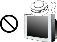
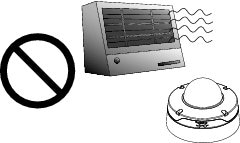
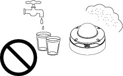
Note ![]() If you use the IP camera outdoors, place the camera and the power supply in a suitable NEMA enclosure.
If you use the IP camera outdoors, place the camera and the power supply in a suitable NEMA enclosure.
|
Warning |

Note ![]() The power adapter that you use with the IP camera must provide power that is within +/-10% of the required power.
The power adapter that you use with the IP camera must provide power that is within +/-10% of the required power.
Note ![]() The equipment is to be connected to a Listed class 2, limited power source.
The equipment is to be connected to a Listed class 2, limited power source.
Installing the IP Camera with a Vandal Resistant Enclosure
To install the IP camera to a ceiling or wall using a vandal resistant (VR) enclosure, perform the following steps.
Procedure
Step 1 ![]() Attach the included alignment sticker to the ceiling or wall.
Attach the included alignment sticker to the ceiling or wall.
Step 2 ![]() Using the circle marks on the sticker, drill at least two pilot holes symmetrically on each side (four holes total) into the ceiling or wall. Then hammer the included wall anchors into the holes.
Using the circle marks on the sticker, drill at least two pilot holes symmetrically on each side (four holes total) into the ceiling or wall. Then hammer the included wall anchors into the holes.
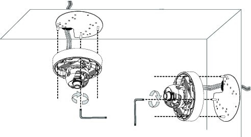
Step 3 ![]() Secure the mounting plate to the ceiling or wall with the four included screws.
Secure the mounting plate to the ceiling or wall with the four included screws.
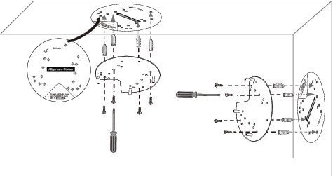
Step 4 ![]() Do one of the following to feed the cables to the IP camera:
Do one of the following to feed the cables to the IP camera:
•![]() Cut out a section of the ceiling or wall that corresponds to the triangular cutout on the alignment sticker, and feed cables through a ceiling or wall.
Cut out a section of the ceiling or wall that corresponds to the triangular cutout on the alignment sticker, and feed cables through a ceiling or wall.
•![]() Use a screwdriver to remove the cutout on the side of the conduit base, connect a cable conduit, and feed the cables through the side of the conduit base.
Use a screwdriver to remove the cutout on the side of the conduit base, connect a cable conduit, and feed the cables through the side of the conduit base.
Step 5 ![]() Perform the following steps to install and connect an RJ45 Ethernet cable.
Perform the following steps to install and connect an RJ45 Ethernet cable.
Note ![]() We recommended using 24AWG (0.51 mm) gauge cable.
We recommended using 24AWG (0.51 mm) gauge cable.
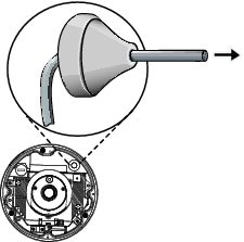
a. ![]() Drill a hole on the rubber seal plug and insert an Ethernet cable (without a connector) through the opening.
Drill a hole on the rubber seal plug and insert an Ethernet cable (without a connector) through the opening.
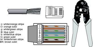
b. ![]() Strip about 1/2 inch (12 mm) of the sheath from the Ethernet cable.
Strip about 1/2 inch (12 mm) of the sheath from the Ethernet cable.
c. ![]() Use an RJ45 crimping tool to attach the Ethernet wires to a connector. When done, connect the cable to the camera's Ethernet RJ45 socket.
Use an RJ45 crimping tool to attach the Ethernet wires to a connector. When done, connect the cable to the camera's Ethernet RJ45 socket.
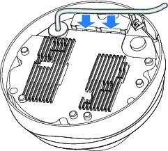
d. ![]() Press the Ethernet cable into the routing path at the bottom of the camera so that the cable will not get in the way when the metal mounting plate is attached.
Press the Ethernet cable into the routing path at the bottom of the camera so that the cable will not get in the way when the metal mounting plate is attached.
Step 6 ![]() (Optional) Perform the following steps to install and connect an external power cable and I/O cables for external devices:
(Optional) Perform the following steps to install and connect an external power cable and I/O cables for external devices:
a. ![]() Disassemble the components of the waterproof connector into parts (A) ~ (F).
Disassemble the components of the waterproof connector into parts (A) ~ (F).
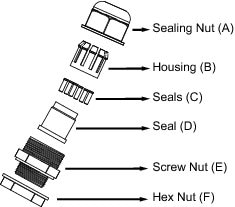
b. ![]() Place the screw nut (E) on the power and I/O cable opening.
Place the screw nut (E) on the power and I/O cable opening.
c. ![]() Feed the power cable through the waterproof connector (F --> E --> D --> B --> A). Be sure to feed enough power cable length through the waterproof connector to connect the power cable to the GPIO block.
Feed the power cable through the waterproof connector (F --> E --> D --> B --> A). Be sure to feed enough power cable length through the waterproof connector to connect the power cable to the GPIO block.

Note ![]() There are 8 holes on the seal (D), and the widest holes with a crack on the side are specific for power cables.
There are 8 holes on the seal (D), and the widest holes with a crack on the side are specific for power cables.
d. ![]() Feed the I/O cables through the waterproof connector (F --> E --> D --> B --> A). Be sure to feed enough I/O cable length through the waterproof connector to connect the I/O cable to the GPIO block.
Feed the I/O cables through the waterproof connector (F --> E --> D --> B --> A). Be sure to feed enough I/O cable length through the waterproof connector to connect the I/O cable to the GPIO block.
The recommended cable gauge is 2.0 ~ 2.8 mm.
e. ![]() Push the seal (D) into the housing (B).
Push the seal (D) into the housing (B).
f. ![]() Insert the seals (C) into unused holes on the seal (D) to avoid moisture.
Insert the seals (C) into unused holes on the seal (D) to avoid moisture.
g. ![]() Secure the sealing nut (A) tightly and hex nut (F) from the bottom of the camera.
Secure the sealing nut (A) tightly and hex nut (F) from the bottom of the camera.
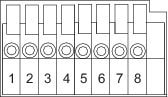
h. ![]() Connect the power and I/O cables to the GPIO terminal block
Connect the power and I/O cables to the GPIO terminal block
|
|
|
1 |
12 VDC- |
|
2 |
12 VDC+ |
|
3 |
24 VAC |
|
4 |
24 VAC |
|
5 |
DI- |
|
6 |
DI+ |
|
7 |
DO- |
|
8 |
DO+ |
Step 7 ![]() Use the included L-type wrench to secure the conduit base to the mounting plate with the three included screws.
Use the included L-type wrench to secure the conduit base to the mounting plate with the three included screws.
Step 8 ![]() Remove the black cover.
Remove the black cover.
Step 9 ![]() (Optional) Use mini cable with BNC connector to temporarily attach an NTSC or PAL compliant analog video display device to the analog video out port on the rear of the IP camera.
(Optional) Use mini cable with BNC connector to temporarily attach an NTSC or PAL compliant analog video display device to the analog video out port on the rear of the IP camera.
Note ![]() The mini cable with BNC adapter is included in the audio/video cables accessory kit, which you can purchase from Cisco (Cisco part number CIVS-AVCABLE).
The mini cable with BNC adapter is included in the audio/video cables accessory kit, which you can purchase from Cisco (Cisco part number CIVS-AVCABLE).
Analog video is enabled by default to allow you to adjust the camera field of view during installation. However, it is not supported as a normal camera feed and is automatically disabled when any of the following camera settings are made:
•![]() The primary video stream frame rate must be set higher than 15 fps.
The primary video stream frame rate must be set higher than 15 fps.
•![]() The secondary video stream must is enabled.
The secondary video stream must is enabled.
Note ![]() We recommend that you disable analog video after installation. To disable analog video, see the Cisco Video Surveillance 3000 Series IP Camera Configuration Guide.
We recommend that you disable analog video after installation. To disable analog video, see the Cisco Video Surveillance 3000 Series IP Camera Configuration Guide.
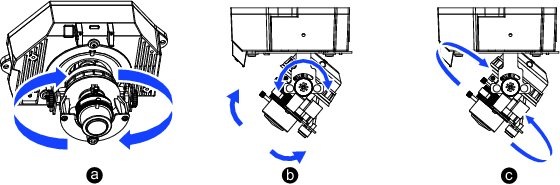
Step 10 ![]() While viewing video from the IP camera, perform the following steps to adjust the 3-axis field of view:
While viewing video from the IP camera, perform the following steps to adjust the 3-axis field of view:
a. ![]() Grip the two tilt adjustment screws and pan the IP camera left or right.
Grip the two tilt adjustment screws and pan the IP camera left or right.
b. ![]() Loosen the two thumb screws, tilt the IP camera, then tighten the thumb screws.
Loosen the two thumb screws, tilt the IP camera, then tighten the thumb screws.
c. ![]() Rotate the IP camera to adjust the horizontal orientation until you achieve a level image.
Rotate the IP camera to adjust the horizontal orientation until you achieve a level image.
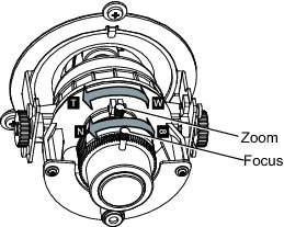
Step 11 ![]() While viewing video from the IP camera, perform the following steps to adjust the focal length and zoom factor.
While viewing video from the IP camera, perform the following steps to adjust the focal length and zoom factor.
a. ![]() Loosen the locking screw on the focus ring, adjust the focal length (from near to infinity [·]) to achieve a sharp image, then tighten the locking screw.
Loosen the locking screw on the focus ring, adjust the focal length (from near to infinity [·]) to achieve a sharp image, then tighten the locking screw.
b. ![]() Loosen the locking screw on the zoom ring, adjust the zoom factor (from telephoto to wide angle) to achieve the desired field of view, then tighten the locking screw. If the focus is no longer sharp after adjusting the zoom, repeat Step 11a to achieve a sharp image.
Loosen the locking screw on the zoom ring, adjust the zoom factor (from telephoto to wide angle) to achieve the desired field of view, then tighten the locking screw. If the focus is no longer sharp after adjusting the zoom, repeat Step 11a to achieve a sharp image.
Step 12 ![]() Install the black cover.
Install the black cover.
Step 13 ![]() (Optional) If the IP camera is installed in a high humidity environment, remove the wrapper from the included silica gel pack and place the pack with the camera inside the VR housing. Ensure that the silica gel pack does not obstruct the IP camera field of view.
(Optional) If the IP camera is installed in a high humidity environment, remove the wrapper from the included silica gel pack and place the pack with the camera inside the VR housing. Ensure that the silica gel pack does not obstruct the IP camera field of view.
Step 14 ![]() Attach the dome cover to the camera by aligning it with the mounting holes.
Attach the dome cover to the camera by aligning it with the mounting holes.
Step 15 ![]() Use the included wrench and tighten the four dome cover screws to secure the dome cover to the camera. Make sure all parts of the camera are securely installed.
Use the included wrench and tighten the four dome cover screws to secure the dome cover to the camera. Make sure all parts of the camera are securely installed.

What to do next
After you install the IP camera, follow the instructions in the "Performing the Initial Setup of the IP Camera" section to access the IP camera through your network.
 Feedback