Threat Containment
Threat Centric NAC Service
Threat Centric Network Access Control (TC-NAC) feature enables you to create authorization policies based on the threat and vulnerability attributes received from the threat and vulnerability adapters. Threat severity levels and vulnerability assessment results can be used to dynamically control the access level of an endpoint or a user.
You can configure the vulnerability and threat adapters to send high fidelity Indications of Compromise (IoC), Threat Detected events, and CVSS scores to Cisco ISE, so that threat-centric access policies can be created to change the privilege and context of an endpoint accordingly.
Cisco ISE supports the following adapters:
-
SourceFire FireAMP
-
Cognitive Threat Analytics (CTA) adapter
-
Qualys

Note
Only the Qualys Enterprise Edition is currently supported for TC-NAC flows.
-
Rapid7 Nexpose
-
Tenable Security Center
When a threat event is detected for an endpoint, you can select the MAC address of the endpoint on the Compromised Endpoints page and apply an ANC policy, such as Quarantine. Cisco ISE triggers CoA for that endpoint and applies the corresponding ANC policy. If ANC policy is not available, Cisco ISE triggers CoA for that endpoint and applies the original authorization policy. You can use the Clear Threat and Vulnerabilities option on the Compromised Endpoints page to clear the threat and vulnerabilities associated with an endpoint (from Cisco ISE system database).
The following attributes are listed under the Threat dictionary:
-
CTA-Course_Of_Action (values can be Internal Blocking, Eradication, or Monitoring)
-
Qualys-CVSS_Base_Score
-
Qualys-CVSS_Temporal_Score
-
Rapid7 Nexpose-CVSS_Base_Score
-
Tenable Security Center-CVSS_Base_Score
-
Tenable Security Center-CVSS_Temporal_Score
The valid range is from 0 to 10 for both Base Score and Temporal Score attributes.
When a vulnerability event is received for an endpoint, Cisco ISE triggers CoA for that endpoint. However, CoA is not triggered when a threat event is received.
You can create an authorization policy by using the vulnerability attributes to automatically quarantine the vulnerable endpoints based on the attribute values. For example:
Any Identity Group & Threat:Qualys-CVSS_Base_Score > 7.0 -> QuarantineNote the following points while enabling the Threat Centric NAC service:
-
The Threat Centric NAC service requires an Apex license.
-
Threat Centric NAC service can be enabled on only one node in a deployment.
-
You can add only one instance of an adapter per vendor for Vulnerability Assessment service. However, you can add multiple instances of FireAMP adapter.
-
You can stop and restart an adapter without losing its configuration. After configuring an adapter, you can stop the adapter at any point of time. The adapter would remain in this state even when the ISE services are restarted. Select the adapter and click Restart to start the adapter again.
Note
When an adapter is in Stopped state, you can edit only the name of the adapter instance; you cannot edit the adapter configuration or the advanced settings.
The Threat Centric NAC Live Logs page (Operations > TC NAC Live Log) lists all the threat and vulnerability events. It displays the incident type, adapter name, matching authorization rule, and authorization profiles (old and new) for an endpoint. You can also view the detailed information for an event.
You can view the threat information for the endpoints on the following pages:
-
Home page > Threat dashboard
-
Context Visibility > Endpoints > Compromised Endpoints
The following alarms are triggered by the Threat Centric NAC service:
-
Adapter not reachable (syslog ID: 91002)—Indicates that the adapter cannot be reached.
-
Adapter Connection Failed (syslog ID: 91018)—Indicates that the adapter is reachable but the connection between the adapter and source server is down.
-
Adapter Stopped Due to Error (syslog ID: 91006)—This alarm is triggered if the adapter is not in the desired state. If this alarm is displayed, check the adapter configuration and server connectivity. Refer to the adapter logs for more details.
-
Adapter Error (syslog ID: 91009)—Indicates that the Qualys adapter is unable to establish a connection with or download information from the Qualys site.
The following reports are available for the Threat Centric NAC service:
-
Adapter Status—The Adapter Status report displays the status of the threat and vulnerability adapters.
-
COA Events—When a vulnerability event is received for an endpoint, Cisco ISE triggers CoA for that endpoint. The CoA Events report displays the status of these CoA events. It also displays the old and new authorization rules and the profile details for these endpoints.
-
Threat Events—The Threat Events report provides a list of all the threat events that Cisco ISE receives from the various adapters that you have configured. Vulnerability Assessment events are not included in this report.
-
Vulnerability Assessment—The Vulnerability Assessment report provides information about the assessments that are happening for your endpoints. You can view this report to check if the assessment is happening based on the configured policy.
-
Total number of events received
-
Total number of threat events
-
Total number of vulnerability events
-
Total number of CoAs issued (to PSN)
The values for these attributes are collected every 5 minutes, so these values represent the count for the last 5 minutes.
The Threat dashboard contains the following dashlets:
-
Total Compromised Endpoints dashlet displays the total number of endpoints (both connected and disconnected endpoints) that are currently impacted on the network.
-
Compromised Endpoints Over Time dashlet displays a historical view of the impact on endpoints for the specified time period.
-
Top Threats dashlet displays the top threats based on the number of endpoints impacted and the severity of the threat.
-
You can use the Threats Watchlist dashlet to analyze the trend of selected events.
The size of the bubbles in the Top Threats dashlet indicates the number of endpoints impacted and the light shaded area indicates the number of disconnected endpoints. The color as well as the vertical scale indicate the severity of the threat. There are two categories of threat—Indicators and Incidents. The severity attribute for Indicator is "Likely_Impact" and the severity attribute for Incident is "Impact_Qualification".
The Compromised Endpoint page displays the matrix view of the endpoints that are impacted and the severity of the impact for each threat category. You can click on the device link to view the detailed threat information for an endpoint.
The Course Of Action chart displays the action taken (Internal Blocking, Eradication, or Monitoring) for the threat incidents based on the CTA-Course_Of_Action attribute received from the CTA adapter.
The Vulnerability dashboard on the Home page contains the following dashlets:
-
Total Vulnerable Endpoints dashlet displays the total number of endpoints that have a CVSS score greater than the specified value. Also displays the total number of connected and disconnected endpoints that have a CVSS score greater than the specified value.
-
Top Vulnerability dashlet displays the top vulnerabilities based on the number of endpoints impacted or the severity of the vulnerability. The size of the bubbles in the Top Vulnerability dashlet indicates the number of endpoints impacted and the light shaded area indicates the number of disconnected endpoints. The color as well as the vertical scale indicates the severity of the vulnerability.
-
You can use the Vulnerability Watchlist dashlet to analyze the trend of selected vulnerabilities over a period of time. Click the search icon in the dashlet and enter the vendor-specific id ("qid" for Qualys ID number) to select and view the trend for that particular ID number.
-
The Vulnerable Endpoints Over Time dashlet displays a historical view of the impact on endpoints over time.
The Endpoint Count By CVSS graph on the Vulnerable Endpoints page shows the number of endpoints that are affected and their CVSS scores. You can also view the list of affected endpoints on the Vulnerable Endpoints page. You can click on the device link to view the detailed vulnerability information for each endpoint.
Threat Centric NAC service logs are included in the support bundle (see the Download Cisco ISE Log Files section in Cisco ISE Admin Guide: Troubleshooting ). Threat Centric NAC service logs are located at support/logs/TC-NAC/.
Enable Threat Centric NAC Service
To configure vulnerability and threat adapters, you must first enable the Threat Centric NAC service. This service can be enabled on only one Policy Service Node in your deployment.
Procedure
| Step 1 |
Choose . |
| Step 2 |
Check the check box next to the PSN on which you want to enable the Threat Centric NAC service and click Edit. |
| Step 3 |
Check the Enable Threat Centric NAC Service check box. |
| Step 4 |
Click Save. |
Add SourceFire FireAMP Adapter
Before you begin
-
You must have an account with SourceFire FireAMP.
-
You must deploy FireAMP clients on all endpoints.
-
You must enable Threat Centric NAC service on the deployment node (see Enable Threat Centric NAC Service).
-
FireAMP adapter uses SSL for REST API calls (to the AMP cloud) and AMQP to receive the events. It also supports the use of proxy. FireAMP adapter uses port 443 for communication.
Procedure
| Step 1 |
Choose Administration > Threat Centric NAC > Third Party Vendors. |
| Step 2 |
Click Add. |
| Step 3 |
Select AMP : Threat from the Vendor drop-down list. |
| Step 4 |
Enter a name for the adapter instance. |
| Step 5 |
Click Save. |
| Step 6 |
Refresh the Vendor Instances listing page. You can configure the adapter only after the adapter status changes to Ready to Configure on the Vendor Instances listing page. |
| Step 7 |
Click the Ready to configure link. |
| Step 8 |
(Optional) If you have configured a SOCKS proxy server to route all the traffic, enter the hostname and the port number of the proxy server. |
| Step 9 |
Select the cloud to which you want to connect. You can select US cloud or EU cloud. |
| Step 10 |
Select the event source to which you want to subscribe. The following options are available:
|
| Step 11 |
Click the FireAMP link and login as admin in FireAMP. Click Allow in the Applications pane to authorize the Streaming Event Export request. You will
be redirected back to Cisco ISE.
|
| Step 12 |
Select the events (for example, suspicious download, connection to suspicious domain, executed malware, java compromise) that you want to monitor. When you change the advanced settings or reconfigure an adapter, if there are any new events added to the AMP cloud, those events are also listed in the Events Listing page. You can choose a log level for the adapter. The available options are: Error, Info, and Debug. The summary of the adapter instance configuration will be displayed in the Configuration Summary page. |
Configure Cognitive Threat Analytics Adapter
Before you begin
-
You must enable Threat Centric NAC service on the deployment node (see Enable Threat Centric NAC Service).
-
Log in to Cisco Cognitive Threat Analytics (CTA) portal via http://cognitive.cisco.com/login and request CTA STIX/TAXII service. For more information, see Cisco ScanCenter Administrator Guide.
-
Cognitive Threat Analytics (CTA) adapter uses TAXII protocol with SSL to poll the CTA cloud for detected threats. It also supports the use of proxy.
-
Import the adapter certificate in to the Trusted Certificate Store. Choose Administration > System > Certificates > Trusted Certificates > Import to import the certificate.
Procedure
| Step 1 |
Choose Administration > Threat Centric NAC > Third Party Vendors. |
| Step 2 |
Click Add. |
| Step 3 |
Select CTA : Threat from the Vendor drop-down list. |
| Step 4 |
Enter a name for the adapter instance. |
| Step 5 |
Click Save. |
| Step 6 |
Refresh the Vendor Instances listing page. You can configure the adapter only after the adapter status changes to Ready to Configure on the Vendor Instances listing page. |
| Step 7 |
Click the Ready to configure link. |
| Step 8 |
Enter the following details:
|
| Step 9 |
Click Next. |
| Step 10 |
Click Advanced Settings to configure the following options:
|
| Step 11 |
Click Finish. |
Note |
CTA works with user identities listed in the web proxy logs as IP addresses or usernames. Specifically, in the case of IP addresses, the IP address of a device that is available through the proxy logs may collide with the IP address of another device on the internal network. For example, roaming users connected via AnyConnect and a split-tunnel directly to the internet could acquire a local IP range address (for example, 10.0.0.X address), which may collide with an address in an overlapping private IP range used in an internal network. We recommend that you take into account the logical network architecture while defining the policies to avoid quarantine actions being applied on mismatched devices. |
Configure Authorization Profiles for CTA Adapter
For each threat event, the CTA adapter returns one of the following values for the Course of Action attribute: Internal Blocking, Monitoring, or Eradication. You can create authorization profiles based on these values.
Procedure
| Step 1 |
Choose Policy > Policy Elements > Authorization > Authorization Profiles. |
| Step 2 |
Click Add. |
| Step 3 |
Enter a name and description for the authorization profile. |
| Step 4 |
Select the Access Type. |
| Step 5 |
Enter the required details and click Submit. |
Configure Authorization Policy using the Course of Action Attribute
You can use the CTA-Course_Of_Action attribute to configure authorization policies for the endpoints for which threat events are reported. This attribute is available in the Threat directory.
You can also create exception rules based on the CTA-Course_Of_Action attribute.
Procedure
| Step 1 |
Choose Policy > Policy Sets You can edit an existing policy rule or create a new
exception rule for the endpoints with threat events.
|
||
| Step 2 |
Create a condition to check for the CTA-Course_Of_Action attribute value and assign the appropriate authorization profile. For example: Network_Access_Authentication_Passed AND ThreatCTA-Course_Of_Action CONTAINS Internal Blocking then blocking (authorization profile)
|
||
| Step 3 |
Click Save. |
Note |
Sometimes CTA sends multiple risks and their associated Course of Action attributes in one incident. For example, it can send "Internal Blocking" and "Monitoring" (course of action attributes) in one incident. In this case, if you have configured an authorization policy to quarantine endpoints using "equals" operator, the endpoints will not be quarantined. For example:
In such cases, you must use "contains" operator in the authorization policy to quarantine the endpoints. For example:
|
Support for Vulnerability Assessment in Cisco ISE
Cisco Identity Services Engine integrates with the following Vulnerability Assessment (VA) Ecosystem Partners to obtain vulnerability results of endpoints that connect to the Cisco ISE network:
-
Qualys—Qualys is a cloud-based assessment system with scanner appliances deployed in the network. Cisco ISE allows you to configure an adapter that communicates with Qualys and obtains the VA results. You can configure the adapter from the Admin portal. You need a Cisco ISE administrator account with Super Admin privileges to configure the adapter. The Qualys adapter uses REST APIs to communicate with the Qualys Cloud Service. You need a user account in Qualys with Manager privileges to access the REST APIs. Cisco ISE uses following Qualys REST APIs :
-
Host Detection List API—To check the last scan results of the endpoint
-
Scan API—To trigger an on-demand scan of the endpoint
-
-
Rapid7 Nexpose—Cisco ISE integrates with Rapid 7 Nexpose, a vulnerability management solution, to help detect vulnerabilities and enables you to respond to such threats quickly. Cisco ISE receives the vulnerability data from Nexpose and based on the policies that you configure in ISE, it quarantines the affected endpoints. From the Cisco ISE dashboard, you can view the affected endpoint and take appropriate action.
Cisco ISE has been tested with Nexpose Release 6.4.1.
-
Tenable Security Center (Nessus scanner)—Cisco ISE integrates with Tenable SecurityCenter and receives the vulnerability data from Tenable Nessus scanner (managed by Tenable SecurityCenter) and based on the policies that you configure in ISE, it quarantines the affected endpoints. From the Cisco ISE dashboard, you can view the affected endpoints and take appropriate action.
Cisco ISE has been tested with Tenable SecurityCenter 5.3.2.
The results from the ecosystem partner are converted in to a Structured Threat Information Expression (STIX) representation and based on this value, a Change of Authorization (CoA) is triggered, if needed, and the appropriate level of access is granted to the endpoint.
The time taken to assess endpoints for vulnerabilities depends on various factors and hence VA cannot be performed in real time. The factors that affect the time taken to assess an endpoint for vulnerabilities include:
-
Vulnerability assessment ecosystem
-
Type of vulnerabilities scanned for
-
Type of scans enabled
-
Network and system resources allocated by the ecosystem for the scanner appliances
In this release of Cisco ISE, only endpoints with IPv4 addresses can be assessed for vulnerabilities.
Enable and Configure Vulnerability Assessment Service
To enable and configure Vulnerability Assessment Service in Cisco ISE, perform the following tasks:
Procedure
| Step 1 | |
| Step 2 |
To configure:
|
| Step 3 | |
| Step 4 |
Configure Exception Rule to Quarantine a Vulnerable Endpoint. |
Enable Threat Centric NAC Service
To configure vulnerability and threat adapters, you must first enable the Threat Centric NAC service. This service can be enabled on only one Policy Service Node in your deployment.
Procedure
| Step 1 |
Choose . |
| Step 2 |
Check the check box next to the PSN on which you want to enable the Threat Centric NAC service and click Edit. |
| Step 3 |
Check the Enable Threat Centric NAC Service check box. |
| Step 4 |
Click Save. |
Configure Qualys Adapter
Cisco ISE supports the Qualys Vulnerability Assessment Ecosystem. You must create a Qualys adapter for Cisco ISE to communicate with Qualys and obtain the VA results.
Before you begin
-
You must have the following user accounts:
-
Admin user account in Cisco ISE with Super Admin privileges to be able to configure a vendor adapter.
-
User account in Qualys with Manager privileges
-
-
Ensure that you have appropriate Qualys license subscriptions. You need access to the Qualys Report Center, Knowledge Base (KBX), and API. Contact your Qualys Account Manager for details.
-
Import the Qualys server certificate in to the Trusted Certificates store in Cisco ISE (Administration > Certificates > Certificate Management > Trusted Certificates > Import). Ensure that the appropriate root and intermediate certificates are imported (or present) in the Cisco ISE Trusted Certificates store.
-
Refer to the Qualys API Guide for the following configurations:
-
Ensure that you have enabled CVSS Scoring in Qualys (Reports > Setup > CVSS Scoring > Enable CVSS Scoring).
-
Ensure that you add the IP address and subnet mask of your endpoints in Qualys (Assets > Host Assets).
-
Ensure that you have the name of the Qualys option profile. The option profile is the scanner template that Qualys uses for scanning. We recommend that you use an option profile that includes authenticated scans (this option checks the MAC Address of the endpoint as well).
-
-
Cisco ISE communicates with Qualys over HTTPS/SSL (port 443).
Procedure
| Step 1 |
Choose . |
||||||||||||||||||||||||||||
| Step 2 |
Click Add. |
||||||||||||||||||||||||||||
| Step 3 |
From the Vendor drop-down list, choose Qualys:VA. |
||||||||||||||||||||||||||||
| Step 4 |
Enter a name for the adapter instance. For example, Qualys_Instance. The listing page appears with a list of configured adapter instances. |
||||||||||||||||||||||||||||
| Step 5 |
Refresh the Vendor Instances listing page. The status for the newly added Qualys_Instance adapter should change to Ready to Configure. |
||||||||||||||||||||||||||||
| Step 6 |
Click the Ready to Configure link. |
||||||||||||||||||||||||||||
| Step 7 |
Enter the following values in the Qualys configuration screen and click Next.
If the connection to the Qualys server is established, the Scanner Mappings page appears with a list of Qualys scanners. The Qualys scanners from your network appear in this page. |
||||||||||||||||||||||||||||
| Step 8 |
Choose the default scanner that Cisco ISE will use for on-demand scans. |
||||||||||||||||||||||||||||
| Step 9 |
In the PSN to Scanner Mapping area, choose one or more Qualys scanner appliance(s) to the PSN node, and click Next. The Advanced Settings page appears. |
||||||||||||||||||||||||||||
| Step 10 |
Enter the following values in the Advanced Settings page. The settings in this page determine whether an on-demand scan will be triggered or the last scan results will be used for VA.
|
||||||||||||||||||||||||||||
| Step 11 |
Click Next to review the Configuration Settings. |
||||||||||||||||||||||||||||
| Step 12 |
Click Finish. |
||||||||||||||||||||||||||||
Configure Nexpose Adapter
You must create a Nexpose adapter for Cisco ISE to communicate with Nexpose and obtain the VA results.
Before you begin
-
Ensure that you have enabled the Threat-Centric NAC service in Cisco ISE.
-
Log in to Nexpose Security Console and create a user account with the following privileges:
-
Manage sites
-
Create reports
-
-
Import the Nexpose server certificate in to the Trusted Certificates store in Cisco ISE (Administration > Certificates > Certificate Management > Trusted Certificates > Import). Ensure that the appropriate root and intermediate certificates are imported (or present) in the Cisco ISE Trusted Certificates store.
-
Cisco ISE communicates with Nexpose over HTTPS/SSL (port 3780).
Procedure
| Step 1 |
Choose . |
||||||||||||||||||||||||||
| Step 2 |
Click Add. |
||||||||||||||||||||||||||
| Step 3 |
From the Vendor drop-down list, choose Rapid7 Nexpose:VA. |
||||||||||||||||||||||||||
| Step 4 |
Enter a name for the adapter instance. For example, Nexpose. The listing page appears with a list of configured adapter instances. |
||||||||||||||||||||||||||
| Step 5 |
Refresh the Vendor Instances listing page. The status for the newly added Nexpose adapter should change to Ready to Configure. |
||||||||||||||||||||||||||
| Step 6 |
Click the Ready to Configure link. |
||||||||||||||||||||||||||
| Step 7 |
Enter the following values in the Nexpose configuration screen and click Next.
|
||||||||||||||||||||||||||
| Step 8 |
Click Next to configure Advanced Settings. |
||||||||||||||||||||||||||
| Step 9 |
Enter the following values in the Advanced Settings page. The settings in this page determine whether an on-demand scan will be triggered or the last scan results will be used for VA.
|
||||||||||||||||||||||||||
| Step 10 |
Click Next to review the Configuration Settings. |
||||||||||||||||||||||||||
| Step 11 |
Click Finish. |
||||||||||||||||||||||||||
Configure Tenable Adapter
You must create a Tenable adapter for Cisco ISE to communicate with Tenable SecurityCenter (Nessus scanner) and obtain the VA results.
Before you begin
Note |
You must configure the following in Tenable SecurityCenter before you can configure the Tenable Adapter in Cisco ISE. Refer to Tenable SecurityCenter Documentation for these configurations. |
-
You must have Tenable Security Center and Tenable Nessus Vulnerability Scanner installed. While registering the Tenable Nessus scanner, ensure that you choose Managed by SecurityCenter in the Registration field.
-
Create a user account with Security Manager privilege in Tenable SecurityCenter.
-
Create a repository in SecurityCenter (Log in to Tenable SecurityCenter with Admin credentials and choose Repository > Add).
-
Add the endpoint IP range to be scanned in the repository.
-
Add Nessus scanner.
-
Create scan zones and assign IP addresses to the scan zones and scanners that are mapped to these scan zones.
-
Create a scan policy for ISE.
-
Add an active scan and associate it with the ISE scan policy. Configure settings, targets (IP/DNS names).
-
Export System and Root certificates from Tenable SecurityCenter and import it in to the Trusted Certificates store in Cisco ISE (Administration > Certificates > Certificate Management > Trusted Certificates > Import). Ensure that the appropriate root and intermediate certificates are imported (or present) in the Cisco ISE Trusted Certificates store.
-
Cisco ISE communicates with Tenable SecurityCenter over HTTPS/SSL (port 443).
Procedure
| Step 1 |
Choose . |
||||||||||||||||||||||||||||
| Step 2 |
Click Add. |
||||||||||||||||||||||||||||
| Step 3 |
From the Vendor drop-down list, choose Tenable Security Center:VA. |
||||||||||||||||||||||||||||
| Step 4 |
Enter a name for the adapter instance. For example, Tenable. The listing page appears with a list of configured adapter instances. |
||||||||||||||||||||||||||||
| Step 5 |
Refresh the Vendor Instances listing page. The status for the newly added Tenable adapter should change to Ready to Configure. |
||||||||||||||||||||||||||||
| Step 6 |
Click the Ready to Configure link. |
||||||||||||||||||||||||||||
| Step 7 |
Enter the following values in the Tenable SecurityCenter configuration screen and click Next.
|
||||||||||||||||||||||||||||
| Step 8 |
Click Next. |
||||||||||||||||||||||||||||
| Step 9 |
Enter the following values in the Advanced Settings page. The settings in this page determine whether an on-demand scan will be triggered or the last scan results will be used for VA.
|
||||||||||||||||||||||||||||
| Step 10 |
Click Next to review the Configuration Settings. |
||||||||||||||||||||||||||||
| Step 11 |
Click Finish. |
||||||||||||||||||||||||||||
Configure Authorization Profile
The authorization profile in Cisco ISE now includes an option to scan endpoints for vulnerabilities. You can choose to run the scan periodically and also specify the time interval for these scans. After you define the authorization profile, you can apply it to an existing authorization policy rule or create a new authorization policy rule.
Before you begin
You must have enabled the Threat Centric NAC service and configured a vendor adapter.
Procedure
| Step 1 |
Choose . |
| Step 2 |
Create a new authorization profile or edit an existing profile. |
| Step 3 |
From the Common Tasks area, check the Assess Vulnerabilities check box. |
| Step 4 |
From the Adapter Instance drop-down list, choose the vendor adapter that you have configured. For example, Qualys_Instance. |
| Step 5 |
Enter the scan interval in hours in the Trigger scan if the time since last scan is greater than text box. Valid range is between 1 and 9999. |
| Step 6 |
Check the Assess periodically using above interval check box. |
| Step 7 |
Click Submit. |
Configure Exception Rule to Quarantine a Vulnerable Endpoint
You can use the following Vulnerability Assessment attributes to configure an exception rule and provide limited access to vulnerable endpoints:
-
Threat:Qualys-CVSS_Base_Score
-
Threat:Qualys-CVSS_Temporal_Score
-
Rapid7 Nexpose-CVSS_Base_Score
-
Tenable Security Center-CVSS_Base_Score
-
Tenable Security Center-CVSS_Temporal_Score
These attributes are available in the Threat directory. Valid value ranges from 0 to 10.
You can choose to quarantine the endpoint, provide limited access (redirect to a different portal), or reject the request.
Procedure
| Step 1 |
Choose . You can edit an existing policy rule or create a new
exception rule to check for VA attributes.
|
| Step 2 |
Create a condition to check for the Qualys score and assign the appropriate authorization profile. For example: Any Identity Group & Threat:Qualys-CVSS_Base_Score > 5 -> Quarantine (authorization profile) |
| Step 3 |
Click Save. |
Vulnerability Assessment Logs
Cisco ISE provides the following logs for troubleshooting VA services.
-
vaservice.log—Contains VA core information and is available in the node that runs the TC-NAC service.
-
varuntime.log—Contains information about the endpoint and the VA flow; is available in the Monitoring node and the node that runs the TC-NAC service.
-
vaaggregation.log—Contains hourly aggregation details about the endpoint vulnerability and is available in the Primary Administration Node.
Deployment and Node Settings
Deployment Settings
The Deployment Nodes page enables you to configure Cisco ISE (Administration, Policy Service, and Monitoring) nodes and to set up a deployment.
Deployment Nodes List Page
The following table describes the fields on the Deployment Nodes List page, which you can use to configure Cisco ISE nodes in a deployment. The navigation path for this page is: .
|
Fields |
Usage Guidelines |
|---|---|
|
Hostname |
Displays the hostname of the node. |
|
Node Type |
Displays the node type. It can be one of the following:
|
|
Personas |
(Only appears if the node type is Cisco ISE) Lists the personas that an Cisco ISE node has assumed. For example, Administration, Policy Service. |
|
Role |
Indicates the role (primary, secondary, or standalone) that the Administration and Monitoring personas have assumed, if these personas are enabled on this node. The role can be any one or more of the following:
|
|
Services |
(Only appears if the Policy Service persona is enabled) Lists the services that run on this Cisco ISE node. Services can include any one of the following:
|
|
Node Status |
Indicates the status of each ISE node in a deployment for data replication.
For more details, click the quick view icon for each ISE node in the Node Status column. |
General Node Settings
| Fields | Usage Guidelines |
|---|---|
| Hostname | Displays the hostname of the Cisco ISE node. |
| FQDN | Displays the fully qualified domain name of the Cisco ISE node. For example, ise1.cisco.com. |
| IP Address | Displays the IP address of the Cisco ISE node. |
| Node Type | Displays the node type. |
| Personas | |
| Administration |
Check this check box if you want a Cisco ISE node to assume the Administration persona. You can enable the Administration persona only on nodes that are licensed to provide the administrative services. Role—Displays the role that the Administration persona has assumed in the deployment. Could take on any one of the following values: Standalone, Primary, Secondary Make Primary—Click this button to make this node your primary Cisco ISE node. You can have only one primary Cisco ISE node in a deployment. The other options on this page will become active only after you make this node primary. You can have only two Administration nodes in a deployment. If the node has a Standalone role, a Make Primary button appears next to it.If the node has a Secondary role, a Promote to Primary button appears next to it.If the node has a Primary role and there are no other nodes registered with it, a Make Standalone button appears next to it. You can click this button to make your primary node a standalone node. |
| Monitoring |
Check this check box if you want a Cisco ISE node to assume the Monitoring persona and function as your log collector. There must be at least one Monitoring node in a distributed deployment. At the time of configuring your Primary PAN, you must enable the Monitoring persona. After you register a secondary Monitoring node in your deployment, you can edit the Primary PAN and disable the Monitoring persona, if required. To configure a Cisco ISE node on a VMware platform as your log collector, use the following guidelines to determine the minimum amount of disk space that you need: 180 KB per endpoint in your network, per day 2.5 MB per Cisco ISE node in your network, per day. You can calculate the maximum disk space that you need based on how many months of data you want to have in your Monitoring node. If there is only one Monitoring node in your deployment, it assumes the standalone role. If you have two Monitoring nodes in your deployment, Cisco ISE displays the name of the other monitoring node for you to configure the Primary-Secondary roles. To configure these roles, choose one of the following:
If you configure one of your Monitoring nodes as primary or secondary, the other Monitoring node automatically becomes the secondary or primary node, respectively. Both the primary and secondary Monitoring nodes receive Administration and Policy Service logs. If you change the role for one Monitoring node to None, the role of the other Monitoring node also becomes None, thereby cancelling the high availability pair After you designate a node as a Monitoring node, you will find this node listed as a syslog target in the following page: Administration > System > Logging > Remote Logging Targets |
| Policy Service | Check this check box to enable any one or all of the following services:
|
| pxGrid | Check this check box to enable pxGrid persona. Cisco pxGrid is used to share the context-sensitive information from Cisco ISE session directory to other policy network systems such as Cisco Adaptive Security Appliance (ASA). The pxGrid framework can also be used to exchange policy and configuration data between nodes like sharing tags and policy objects between ISE and third party vendors, and for non-ISE related information exchanges such as threat information. |
Profiling Node Settings
| Fields | Usage Guidelines | ||
|---|---|---|---|
|
NetFlow |
Check this check box if you want to enable NetFlow per Cisco ISE node that has assumed the Policy Service persona to receive Netflow packets sent from the routers.Choose these options:
|
||
|
DHCP |
Check this check box if you want to enable DHCP per Cisco ISE node that has assumed the Policy Service persona to listen for DHCP packets from IP helper.Choose these options:Port—Enter the DHCP server UDP port number. The default port is 67.
|
||
|
DHCP SPAN |
Check this check box if you want to enable DHCP SPAN per Cisco ISE node that has assumed the Policy Service persona to collect DHCP packets.
|
||
|
HTTP |
Check this check box if you want to enable HTTP per Cisco ISE node that has assumed the Policy Service persona to receive and parse HTTP packets.
|
||
|
RADIUS |
Check this check box if you want to enable RADIUS per ISE node that has assumed the Policy Service persona to collect RADIUS session attributes as well as CDP, LLDP attributes from the IOS Sensor enabled devices. |
||
|
Network Scan (NMAP) |
Check this box to enable the NMAP probe. |
||
|
DNS |
Check this check box if you want to enable DNS per ISE node that has assumed the Policy Service persona to perform a DNS lookup for the FQDN.Enter the timeout period in seconds.
|
||
|
SNMP Query |
Check this check box if you want to enable SNMP Query per ISE node that has assumed the Policy Service persona to poll network devices at specified intervals.Enter values for the following fields: Retries, Timeout, Event Timeout, and an optional Description.
|
||
|
SNMP Trap |
Check this check box if you want to enable SNMP Trap probe per ISE node that has assumed the Policy Service Persona to receive
linkUp, linkDown, and MAC notification traps from the network devices.Choose any of the following:
|
||
|
Active Directory |
Scans the defined Active Directory servers for information about Windows users. |
||
|
pxGrid |
Allows ISE to collect (profile) endpoint attributes over pxGrid. |
Certificate Store Settings
The Certificate Store page enables you to configure certificates in Cisco ISE that can be used for authentication.
Self-Signed Certificate Settings
The following table describes the fields in the Generate Self Signed Certificate page. This page allows you to create system certificates for inter-node communication, EAP-TLS authentication, Cisco ISE web portals, and to communicate with the pxGrid controller. The navigation path for this page is: Administration > System > Certificates > System Certificates > Generate Self Signed Certificate.
| Fields | Usage Guidelines | ||
|---|---|---|---|
|
Select Node |
(Required) The node for which you want to generate the system certificate. |
||
|
Common Name (CN) |
(Required if you do not specify a SAN) By default, the common name is the Fully Qualified Domain Name of the ISE node for which you are generating the self-signed certificate. |
||
|
Organizational Unit (OU) |
Organizational Unit name. For example, Engineering. |
||
|
Organization (O) |
Organization name. For example, Cisco. |
||
|
City (L) |
(Do not abbreviate) City name. For example, San Jose. |
||
|
State (ST) |
(Do not abbreviate) State name. For example, California. |
||
|
Country (C) |
Country name. You must enter the two-letter ISO country code. For example, US. |
||
|
Subject Alternative Name (SAN) |
An IP address, DNS name, or Uniform Resource Identifier (URI)that is associated with the certificate. |
||
|
Key Type |
Specify the algorithm to be used for creating the public key: RSA or ECDSA. |
||
|
Key Length |
Specify the bit size for the public key. The following options are available for RSA:
The following options are available for ECDSA:
Choose 2048 if you plan to get a public CA-signed certificate or deploy Cisco ISE as a FIPS-compliant policy management system. |
||
|
Digest to Sign With |
Choose one of the following hashing algorithm: SHA-1 or SHA-256. |
||
|
Certificate Policies |
Enter the certificate policy OID or list of OIDs that the certificate should conform to. Use comma or space to separate the OIDs. |
||
|
Expiration TTL |
Specify the number of days after which the certificate will expire. |
||
|
Friendly Name |
Enter a friendly name for the certificate. If you do not specify a name, Cisco ISE automatically creates a name in the format <common name> # <issuer> # <nnnnn> where <nnnnn> is a unique five-digit number. |
||
|
Allow Wildcard Certificates |
Check this check box if you want to generate a self-signed wildcard certificate (a certificate that contains an asterisk (*) in any Common Name in the Subject and/or the DNS name in the Subject Alternative Name. For example, DNS name assigned to the SAN can be *.amer.cisco.com. |
||
|
Usage |
Choose the service for which this system certificate should be used:
|
Certificate-Signing Request Settings
Cisco ISE allows you to generate CSRs for all the nodes in your deployment from the Admin portal in a single request. Also, you can choose to generate the CSR for a single node or multiple both nodes in the deployment. If you choose to generate a CSR for a single node, ISE automatically substitutes the Fully Qualified Domain Name (FQDN) of the particular node in the CN= field of the certificate subject. If you choose to include an entry in the Subject Alternative Name (SAN) field of the certificate, you must enter the FQDN of the ISE node in addition to other SAN attributes. If you choose to generate CSRs for all the nodes in your deployment, check the Allow Wildcard Certificates check box and enter the wildcard FQDN notation in the SAN field (DNS name), for example, *.amer.example.com. If you plan to use the certificate for EAP Authentication, do not enter the wildcard value in the CN= field.
With the use of wildcard certificates, you no longer have to generate a unique certificate for each Cisco ISE node. Also, you no longer have to populate the SAN field with multiple FQDN values to prevent certificate warnings. Using an asterisk (*) in the SAN field allows you to share a single certificate across multiple both nodes in a deployment and helps prevent certificate name mismatch warnings. However, use of wildcard certificates is considered less secure than assigning a unique server certificate for each Cisco ISE node.
The following table describes the fields in the Certificate Signing Request (CSR) page, which you can use to generate a CSR that can be signed by a Certificate Authority (CA). The navigation path for this page is: .
| Field | Usage Guidelines | ||||
|---|---|---|---|---|---|
|
Certificate(s) will be used for |
Choose the service for which you are going to use the certificate: Cisco ISE Identity Certificates
Cisco ISE Certificate Authority Certificates
|
||||
|
Allow Wildcard Certificates |
Check this check box to use a wildcard character (*) in the CN and/or the DNS name in the SAN field of the certificate. If you check this check box, all the nodes in the deployment are selected automatically. You must use the asterisk (*) wildcard character in the left-most label position. If you use wildcard certificates, we recommend that you partition your domain space for greater security. For example, instead of *.example.com, you can partition it as *.amer.example.com. If you do not partition your domain, it can lead to security issues. |
||||
|
Generate CSRs for these Nodes |
Check the check boxes next to the nodes for which you want to generate the certificate. To generate a CSR for select nodes in the deployment, you must uncheck the Allow Wildcard Certificates option. |
||||
|
Common Name (CN) |
By default, the common name is the FQDN of the ISE node for which you are generating the CSR. $FQDN$ denotes the FQDN of the ISE node. When you generate CSRs for multiple nodes in the deployment, the Common Name field in the CSRs is replaced with the FQDN of the respective ISE nodes. |
||||
|
Organizational Unit (OU) |
Organizational Unit name. For example, Engineering. |
||||
|
Organization (O) |
Organization name. For example, Cisco. |
||||
|
City (L) |
(Do not abbreviate) City name. For example, San Jose. |
||||
|
State (ST) |
(Do not abbreviate) State name. For example, California. |
||||
|
Country (C) |
Country name. You must enter the two-letter ISO country code. For example, US. |
||||
|
Subject Alternative Name (SAN) |
An IP address, DNS name, Uniform Resource Identifier (URI), or Directory Name that is associated with the certificate.
|
||||
|
Key Type |
Specify the algorithm to be used for creating the public key: RSA or ECDSA. |
||||
|
Key Length |
Specify the bit size for the public key. The following options are available for RSA:
The following options are available for ECDSA:
Choose 2048 or greater if you plan to get a public CA-signed certificate or deploy Cisco ISE as a FIPS-compliant policy management system. |
||||
|
Digest to Sign With |
Choose one of the following hashing algorithm: SHA-1 or SHA-256. |
||||
|
Certificate Policies |
Enter the certificate policy OID or list of OIDs that the certificate should conform to. Use comma or space to separate the OIDs. |
Issued and Revoked Certificates
The following table describes the fields on the Overview of Issued and Revoked Certificates page. The PSN nodes in your deployment issue certificates to endpoints. This page provides you information about the endpoint certificates issued by each of the PSN nodes in your deployment. The navigation path for this page is: Administration > System > Certificates > Overview.
| Fields | Usage Guidelines |
|---|---|
|
Node Name |
Name of the Policy Service node (PSN) that issued the certificate. |
|
Certificates Issued |
Number of endpoint certificates issued by the PSN node. |
|
Certificates Revoked |
Number of revoked endpoint certificates (certificates that were issued by the PSN node). |
|
Certificates Requests |
Number of certificate-based authentication requests processed by the PSN node. |
|
Certificates Failed |
Number of failed authentication requests processed by the PSN node. |
Check the Status of the Certificates (OCSP or CRL).
Cisco ISE checks the Certificate Revocation Lists (CRL) periodically. Using this page, you can configure Cisco ISE to check ongoing sessions against CRLs that are downloaded automatically. You can specify the time of the day when the OCSP or CRL checks should begin each day and the time interval in hours that Cisco ISE waits before checking the OCSP server or CRLs again.
The following table describes the fields in the Certificate Periodic Check Settings page, which you can use to specify the time interval for checking the status of certificates (OCSP or CRL). The navigation path for this page is: .
| Field | Usage Guidelines |
|---|---|
|
Certificate Check Settings |
|
|
Check ongoing sessions against automatically retrieved CRL |
Check this check box if you want Cisco ISE to check ongoing sessions against CRLs that are automatically downloaded. |
|
CRL/OCSP Periodic Certificate Checks |
|
|
First check at |
Specify the time of the day when the CRL or OCSP check should begin each day. Enter a value between 00:00 and 23:59 hours. |
|
Check every |
Specify the time interval in hours that Cisco ISE waits before checking the CRL or OCSP server again. |
System Certificate Import Settings
The following table describes the fields in the Import System Certificate page that you can use to import a server certificate. The navigation path for this page is: Administration > System > Certificates > System Certificates > Import.
| Fields | Description |
|---|---|
|
Select Node |
(Required) Choose the Cisco ISE node on which you want to import the system certificate. |
|
Certificate File |
(Required) Click Browse to select the certificate file from your local system. |
|
Private Key File |
(Required) Click Browse to select the private key file. |
|
Password |
(Required) Enter the password to decrypt the private key file. |
|
Friendly Name |
Enter a friendly name for the certificate. If you do not specify a name, Cisco ISE automatically creates a name in the format <common name> # <issuer> # <nnnnn> where <nnnnn> is a unique five-digit number. |
|
Allow Wildcard Certificates |
Check this check box if you want to import a wildcard certificate (a certificate that contains an asterisk (*) in any Common Name in the Subject and/or the DNS name in the Subject Alternative Name. For example, DNS name assigned to the SAN can be *.amer.cisco.com. If you check this check box, Cisco ISE imports this certificate to all the other nodes in the deployment. |
|
Validate Certificate Extensions |
Check this check box if you want Cisco ISE to validate the certificate extensions. If you check this check box and the certificate that you are importing contains a basic constraints extension with the CA flag set to true, ensure that the key usage extension is present, and that the keyEncipherment bit or the keyAgreement bit, or both, are also set. |
|
Usage |
Choose the service for which this system certificate should be used:
|
Trusted Certificate Store Page
The following table describes the fields on the Trusted Certificates Store page, which you can use to view the certificates that are added to the Administration node. The navigation path for this page is: Administration > System > Certificates > Trusted Certificates.
|
Fields |
Usage Guidelines |
|---|---|
|
Friendly Name |
Displays the name of the certificate. |
|
Status |
Enabled or Disabled. If Disabled, ISE will not use the certificate for establishing trust. |
|
Trusted for |
Displays the service for which the certificate is used. |
|
Issued To |
Common Name (CN) of the certificate subject. |
|
Issued By |
Common Name (CN) of the certificate issuer. |
|
Valid From |
The “Not Before” certificate attribute. |
|
Expiration Date |
The “Not After” certificate attribute. |
|
Expiration Status |
Provides information about the status of the certificate expiration. There are five icons and categories of informational message that appear in this column:
|
Edit Certificate Settings
The following table describes the fields on the Certificate Store Edit Certificate page, which you can use to edit the Certificate Authority (CA) certificate attributes. The navigation path for this page is: .
|
Fields |
Usage Guidelines |
|---|---|
|
Certificate Issuer |
|
|
Friendly Name |
Enter a friendly name for the certificate. |
|
Status |
Choose Enabled or Disabled. If Disabled, ISE will not use the certificate for establishing trust. |
|
Description |
Enter an optional description. |
|
Usage |
|
|
Trust for authentication within ISE |
Check the check box if you want this certificate to verify server certificates (from other ISE nodes or LDAP servers). |
|
Trust for client authentication and Syslog |
(Applicable only if you check the Trust for authentication within ISE check box) Check the check box if you want this certificate to be used to:
|
|
Trust for authentication of Cisco Services |
Check this check box if you want this certificate to be used to trust external Cisco services such as the feed service. |
|
Certificate Status Validation |
ISE supports two ways of checking the revocation status of a client or server certificate that is issued by a particular CA. The first is to validate the certificate using the Online Certificate Status Protocol (OCSP), which makes a request to an OCSP service maintained by the CA. The second is to validate the certificate against a Certificate Revocation List (CRL) which is downloaded from the CA into ISE. Both of these methods can be enabled, in which case OCSP is used first, and only if a status determination cannot be made then the CRL is used. |
|
Validate Against OCSP Service |
Check the check box to validate the certificate against OCSP services. You must first create an OCSP Service to be able to check this box. |
|
Reject the request if OCSP returns UNKNOWN status |
Check the check box to reject the request if certificate status is not determined by OCSP. If you check this check box, an unknown status value returned by the OCSP service will cause ISE to reject the client or server certificate currently being evaluated. |
|
Reject the request if OCSP Responder is unreachable |
Check the check box for ISE to reject the request if the OCSP Responder is not reachable. |
|
Download CRL |
Check the check box for the Cisco ISE to download a CRL. |
|
CRL Distribution URL |
Enter the URL to download the CRL from a CA. This field will be automatically populated if it is specified in the certificate authority certificate. The URL must begin with “http”, “https”, or “ldap.” |
|
Retrieve CRL |
The CRL can be downloaded automatically or periodically. Configure the time interval between downloads. |
|
If download failed, wait |
Configure the time interval to wait before Cisco ISE tries to download the CRL again. |
|
Bypass CRL Verification if CRL is not Received |
Check this check box, for the client requests to be accepted before the CRL is received. If you uncheck this check box, all client requests that use certificates signed by the selected CA will be rejected until Cisco ISE receives the CRL file. |
|
Ignore that CRL is not yet valid or expired |
Check this check box if you want Cisco ISE to ignore the start date and expiration date and continue to use the not yet active or expired CRL and permit or reject the EAP-TLS authentications based on the contents of the CRL. Uncheck this check box if you want Cisco ISE to check the CRL file for the start date in the Effective Date field and the expiration date in the Next Update field. If the CRL is not yet active or has expired, all authentications that use certificates signed by this CA are rejected. |
Trusted Certificate Import Settings
The following table describes the fields on the Trusted Certificate Import page, which you can use to add Certificate Authority (CA) certificates to Cisco ISE. The navigation path for this page is: .
|
Fields |
Description |
|---|---|
|
Certificate File |
Click Browse to choose the certificate file from the computer that is running the browser. |
|
Friendly Name |
Enter a friendly name for the certificate. If you do not specify a name, Cisco ISE automatically creates a name in the format <common name># <issuer># <nnnnn>, where <nnnnn> is a unique five-digit number. |
|
Trust for authentication within ISE |
Check the check box if you want this certificate to be used to verify server certificates (from other ISE nodes or LDAP servers). |
|
Trust for client authentication and Syslog |
(Applicable only if you check the Trust for authentication within ISE check box) Check the check box if you want this certificate to be used to:
|
|
Trust for authentication of Cisco Services |
Check this check box if you want this certificate to be used to trust external Cisco services such as the feed service. |
|
Validate Certificate Extensions |
(Only if you check both the Trust for client authentication and Enable Validation of Certificate Extensions options) Ensure that the “keyUsage” extension is present and the “keyCertSign” bit is set, and that the basic constraints extension is present with the CA flag set to true. |
|
Description |
Enter an optional description. |
OCSP Client Profile Settings
The following table describes the fields on the OCSP Client Profile page, which you can use to configure OCSP client profiles. The navigation path for this page is .
| Field | Usage Guidelines |
|---|---|
|
Name |
Name of the OCSP Client Profile. |
|
Description |
Enter an optional description. |
|
Configure OCSP Responder |
|
|
Enable Secondary Server |
Check this check box to enable a secondary OCSP server for high availability. |
|
Always Access Primary Server First |
Use this option to check the primary server before trying to move to the secondary server. Even if the primary was checked earlier and found to be unresponsive, Cisco ISE will try to send a request to the primary server before moving to the secondary server. |
|
Fallback to Primary Server After Interval n Minutes |
Use this option when you want Cisco ISE to move to the secondary server and then fall back to the primary server again. In this case, all other requests are skipped, and the secondary server is used for the amount of time that is configured in the text box. The allowed time range is 1 to 999 minutes. |
|
Primary and Secondary Servers |
|
|
URL |
Enter the URL of the primary and/or secondary OCSP server. |
|
Enable Nonce Extension Support |
You can configure a nonce to be sent as part of the OCSP request. The Nonce includes a pseudo-random number in the OCSP request. It is verified that the number that is received in the response is the same as the number that is included in the request. This option ensures that old communications cannot be reused in replay attacks. |
|
Validate Response Signature |
The OCSP responder signs the response with one of the following certificates:
|
|
Use OCSP URLs specified in Authority Information Access (AIA) |
Click the radio button to use the OCSP URLs specified in the Authority Information Access extension. |
|
Response Cache |
|
|
Cache Entry Time To Live n Minutes |
Enter the time in minutes after which the cache entry expires. Each response from the OCSP server holds a nextUpdate value. This value shows when the status of the certificate will be updated next on the server. When the OCSP response is cached, the two values (one from the configuration and another from response) are compared, and the response is cached for the period of time that is the lowest value of these two. If the nextUpdate value is 0, the response is not cached at all. Cisco ISE will cache OCSP responses for the configured time. The cache is not replicated or persistent, so when Cisco ISE restarts, the cache is cleared. The OCSP cache is used in
order to maintain the OCSP responses and for the following reasons:
By default, the cache is set to 2 minutes for the internal CA OCSP client profile. If an endpoint authenticates a second time within 2 minutes of the first authentication, the OCSP cache is used and the OCSP responder is not queried. If the endpoint certificate has been revoked within the cache period, the previous OCSP status of Good will be used and the authentication succeeds. Setting the cache to 0 minutes prevents any responses from being cached. This option improves security, but decreases authentication performance. |
|
Clear Cache |
Click Clear Cache to clear entries of all the certificate authorities that are connected to the OCSP service. In a deployment, Clear Cache interacts with all the nodes and performs the operation. This mechanism updates every node in the deployment. |
Internal CA Settings
The following table describes the fields in the internal CA settings page. You can view the internal CA settings and disable the internal CA service from this page. The navigation path for this page is: Administration > System > Certificates > Internal CA Settings.
| Fields | Usage Guidelines |
|---|---|
|
Disable Certificate Authority |
Click this button to disable the internal CA service. |
|
Host Name |
Host name of the Cisco ISE node that is running the CA service. |
|
Personas |
Cisco ISE node personas that are enabled on the node running the CA service. For example, Administration, Policy Service, etc. |
|
Role(s) |
The role(s) assumed by the Cisco ISE node running the CA service. For example, Standalone or Primary or Secondary. |
|
CA, EST & OCSP Responder Status |
Enabled or disabled |
|
OCSP Responder URL |
URL for Cisco ISE node to access the OCSP server. |
|
SCEP URL |
URL for the Cisco ISE node to access the SCEP server. |
Certificate Template Settings
The following table describes the fields in the CA Certificate Template page, which you can use to define a SCEP RA profile that will be used by the client provisioning policy. The navigation path for this page is: Administration > System > Certificates > Certificate Templates > Add.
Note |
We do not support UTF-8 characters in the certificate template fields (Organizational Unit, Organization, City, State, and Country). Certificate provisioning fails if UTF-8 characters are used in the certificate template. |
| Fields | Usage Guidelines |
|---|---|
|
Name |
(Required) Enter a name for the certificate template. For example, Internal_CA_Template. |
|
Description |
(Optional) Enter a description. |
|
Common Name (CN) |
(Display only) Common name is autopopulated with the username. |
|
Organizational Unit (OU) |
Organizational Unit name. For example, Engineering. |
|
Organization (O) |
Organization name. For example, Cisco. |
|
City (L) |
(Do not abbreviate) City name. For example, San Jose. |
|
State (ST) |
(Do not abbreviate) State name. For example, California. |
|
Country (C) |
Country name. You must enter the two-letter ISO country code. For example, US. |
|
Subject Alternative Name (SAN) |
(Display only) MAC address of the endpoint. |
|
Key Type |
RSA or ECC |
|
Key Size |
(Applicable only if you choose RSA) Specify a key size of 1024 or higher. |
|
Curve Type |
(Applicable only if you choose ECC) Specify a curve type (the default is P-384). |
|
SCEP RA Profile |
Choose the ISE Internal CA or an external SCEP RA profile that you have created. |
|
Valid Period |
Enter the number of days after which the certificate expires. |
|
Extended Key Usage |
|
|
Client Authentication |
Check this check box if you want to use this certificate for client authentication. |
|
Server Authentication |
Check this check box if you want to use this certificate for server authentication. |
Logging Settings
These pages allow you to configure the severity of debug logs, create an external log target, and enable Cisco ISE to send log messages to these external log targets.
Remote Logging Target Settings
The following table describes the fields on the Remote Logging Targets page, which you can use to create external locations (syslog servers) to store logging messages. The navigation path for this page is: .
|
Fields |
Usage Guidelines |
|---|---|
|
Name |
Enter the name of the new target. |
|
Target Type |
Select the target type. By default it is set to UDP Syslog. |
|
Description |
Enter a brief description of the new target. |
|
IP Address |
Enter the IP address or hostname of the destination machine where you want to store the logs. |
|
Port |
Enter the port number of the destination machine. |
|
Facility Code |
Choose the syslog facility code to be used for logging. Valid options are Local0 through Local7. |
|
Maximum Length |
Enter the maximum length of the remote log target messages. Valid options are from 200 to 1024 bytes. |
|
Buffer Message When Server Down |
Check this check-box if you want Cisco ISE to buffer the syslog messages when TCP syslog targets and secure syslog targets are unavailable. ISE retries sending the messages to the target when the connection resumes. After the connection resumes, messages are sent by the order from oldest to newest and buffered messages are always sent before new messages. If the buffer is full, old messages are discarded. |
|
Buffer Size (MB) |
Set the buffer size for each target. By default, it is set to 100 MB. Changing the buffer size clears the buffer and all existing buffered messages for the specific target are lost. |
|
Reconnect Timeout (Sec) |
Give in seconds how long will the TCP and secure syslogs be kept before being discarded, when the server is down. |
|
Select CA Certificate |
Select a client certificate. |
|
Ignore Server Certificate Validation |
Check this check-box if you want ISE to ignore server certificate authentication and accept any syslog server. By default, this option is set to off unless the system is in FIPS mode when this is disabled. |
Logging Category Settings
The following table describes the fields on the Logging Categories page, which you can use to configure the log severity level and choose logging targets for the logs of selected categories to be stored. The navigation path for this page is Administration > System > Logging > Logging Categories.
|
Fields |
Usage Guidelines |
|---|---|
|
Name |
Displays the name of the logging category. |
|
Log Severity Level |
Allows you to choose the severity level for the diagnostic logging categories from the following options:
|
|
Local Logging |
Check this check box to enable logging event for the category on the local node. |
|
Target |
Allows you to change the targets for a category by transferring the targets between the Available and the Selected boxes using the left and right icons. The Available box contains the existing logging targets, both local (predefined) and external (user-defined). The Selected box, which is initially empty, contains the selected targets for the specific category. |
Maintenance Settings
These pages help you to manage data using the backup, restore, and data purge features.
Repository Settings
The following table describes the fields on the Repository List page, which you can use to create repositories to store your backup files. The navigation path for this page is: .
|
Fields |
Usage Guidelines |
||
|---|---|---|---|
|
Repository |
Enter the name of the repository. Alphanumeric characters are allowed and the maximum length is 80 characters. |
||
|
Protocol |
Choose one of the available protocols that you want to use. |
||
|
Server Name |
(Required for TFTP, HTTP, HTTPS, FTP, SFTP, and NFS) Enter the hostname or IPv4 address of the server where you want to create the repository.
|
||
|
Path |
Enter the path to your repository. The path must be valid and must exist at the time you create the repository. This value can start with two forward slashes (//) or a single forward slash (/) denoting the root directory of the server. However, for the FTP protocol, a single forward slash (/) denotes the FTP user's home directory and not the root directory. |
||
|
Enable PKI authentication |
(Optional; applicable only for SFTP repository) Check this check box if you want to enable RSA Public Key Authentication in SFTP repository. |
||
|
User Name |
(Required for FTP, SFTP, and NFS) Enter the username that has write permission to the specified server. Only alphanumeric characters are allowed. |
||
|
Password |
(Required for FTP, SFTP, and NFS) Enter the password that will be used to access the specified server. Passwords can consist of the following characters: 0 through 9, a through z, A through Z, -, ., |, @, #,$, %, ^, &, *, (, ), +, and =. |
On-Demand Backup Settings
| Fields | Usage Guidelines |
|---|---|
|
Backup Name |
Enter the name of your backup file. |
|
Repository Name |
Repository where your backup file should be saved. You cannot enter a repository name here. You can only choose an available repository from the drop-down list. Ensure that you create the repository before you run a backup. |
|
Encryption Key |
This key is used to encrypt and decrypt the backup file. |
Scheduled Backup Settings
| Fields | Usage Guidelines |
|---|---|
|
Name |
Enter a name for your backup file.You can enter a descriptive name of your choice. Cisco ISE appends the timestamp to the backup filename and stores it in the repository. You will have unique backup filenames even if you configure a series of backups.On the Scheduled Backup list page, the backup filename will be prepended with “backup_occur” to indicate that the file is a kron occurrence job . |
|
Description |
Enter a description for the backup. |
|
Repository Name |
Select the repository where your backup file should be saved.You cannot enter a repository name here. You can only choose an available repository from the drop-down list. Ensure that you create the repository before you run a backup. |
|
Encryption Key |
Enter a key to encrypt and decrypt the backup file. |
|
Schedule Options |
Choose the frequency of your scheduled backup and fill in the other options accordingly. |
Schedule Policy Export Settings
| Fields | Usage Guidelines |
|---|---|
|
Encryption |
|
|
Encryption Key |
Enter a key to encrypt and decrypt the export data. This field will be enabled only if you select the Export with Encryption Key option. |
|
Destination |
|
|
Download file to local computer |
Allows you to download the policy export file to your local system. |
|
Email file to |
Enter multiple email addresses separated by a comma. |
|
Repository |
Select the repository where your export data should be saved. You cannot enter a repository name here. You can only choose an available repository from the drop-down list. Ensure that you create the repository before scheduling the policy export. |
|
Export Now |
Click this option to export the data to the specified repository immediately. |
| Schedule | |
|
Schedule Options |
Choose the frequency of the export schedule and enter the other details accordingly. |
Admin Access Settings
These pages enable you to configure access settings for administrators.
Administrator Password Policy Settings
The following table describes the fields on the Administrator Password Policy page, which you can use to define a criteria that administrator passwords should meet. The navigation path for this page is:.
|
Fields |
Usage Guidelines |
|---|---|
|
Minimum Length |
Specifies the minimum length of the password (in characters). The default is six characters. |
|
Password must not contain |
Admin name or its characters in reverse order—Check this check box to restrict the use of the administrator username or its characters in reverse order. |
|
"cisco" or its characters in reverse order—Check this check box to restrict the use of the word “cisco” or its characters in reverse order. |
|
|
This word or its characters in reverse order—Check this check box to restrict the use of any word that you define or its characters in reverse order. |
|
|
Repeated characters four or more times consecutively—Check this check box to restrict the use of repeated characters four or more times consecutively. |
|
|
Dictionary words, their characters in reverse order or their letters replaced with other characters—Check this check box to restrict the use of dictionary words, their characters in reverse order or their letters replaced with other characters. Substitution of "$" for "s", "@" for "a", "0" for "o", "1" for "l", "!" for "i", "3" for "e" is not permitted. For example, Pa$$w0rd
|
|
|
Required Characters |
Specifies that the administrator password must contain at least one character of the type that you choose from the following choices:
|
|
Password History |
Specifies the number of previous passwords from which the new password must be different to prevent the repeated use of the same password. Also, specifies the number of characters that must be different from the previous password. Enter the number of days before which you cannot reuse a password. |
|
Password Lifetime |
Specifies the following options to force users to change passwords after a specified time period:
|
|
Display Network Device Sensitive Data |
|
|
Require Admin Password |
Check this check box if you want the admin user to enter the login password to view network device sensitive data such as shared secrets and passwords. |
|
Password cached for |
The password that is entered by the admin user is cached for this time period. The admin user will not be prompted to enter the password again during this period to view network device sensitive data. The valid range is from 1 to 60 minutes. |
Session Timeout and Session Information Settings
The following table describes the fields on the Session page, which you can use to define session timeout and terminate an active administrative session. The navigation path for this page is:.
|
Fields |
Usage Guidelines |
|---|---|
|
Session Timeout |
|
|
Session Idle Timeout |
Enter the time in minutes that you want Cisco ISE to wait before it logs out the administrator if there is no activity. The default value is 60 minutes. The valid range is from 6 to 100 minutes. |
|
Session Info |
|
|
Invalidate |
Check the check box next to the session ID that you want to terminate and click Invalidate. |
Settings
These pages enable you to configure general settings for the various services.
Posture General Settings
The following table describes the fields on the Posture General Settings page, which you can use to configure general posture settings such as remediation time and posture status. The navigation path for this page is:.
|
Fields |
Usage Guidelines |
|---|---|
|
Remediation Timer |
Enter a time value in minutes. The default value is 4 minutes. The valid range is 1 to 300 minutes. |
|
Network Transition Delay |
Enter a time value in seconds. The default value is 3 seconds. The valid range is 2 to 30 seconds. |
|
Default Posture Status |
Choose Compliant or Noncompliant. The non-agent devices like Linux assumes this status while connecting to the network. |
|
Automatically Close Login Success Screen After |
Check the check box to close the login success screen automatically after the specified time. Enter a time value in seconds, in the field next to the check box. You can configure the timer to close the login screen automatically between 0 to 300 seconds. If the time is set to zero, then the NAC Agents and Web Agents do not display the login success screen. |
|
Continuous Monitoring Interval |
Specify the time interval after which AnyConnect should start sending monitoring data. For application conditon For application and hardware conditions, the default value is 5 minutes. |
|
Acceptable Use Policy in Stealth Mode |
Choose Block in stealth mode to move a client to noncompliant posture status, if your company's network-usage terms and conditions are not met. |
|
Posture Lease |
|
| Perform posture assessment every time a user connects to the network |
Select this option to initiate posture assessment every time the user connects to network |
| Perform posture assessment every n days |
Select this option to initiate posture assessment after the specified number of days although the client is already postured Compliant. |
| Cache Last Known Good State |
Check this check box for Cisco ISE to cache the result of posture assessment. By default, this field is disabled. |
| Last Known Good State |
(Applicable only when you check the Cache Last Known Good State check box) Cisco ISE caches the result of posture assessment for the amount of time specified in this field. Valid values are 1 to 30 days, or 1 to 720 hours, or 1 to 43200 minutes. |
Posture Reassessment Configuration Settings
The following table describes the fields in the Posture Reassessment Configurations Page, which you can use to configure posture reassessment. The navigation path for this page is: .
|
Fields |
Usage Guidelines |
||
|---|---|---|---|
|
Configuration Name |
Enter the name of PRA configuration. |
||
|
Configuration Description |
Enter a description for PRA configuration. |
||
|
Use Reassessment Enforcement? |
Check the check box to apply the PRA configurations for the user identity groups. |
||
|
Enforcement Type |
Choose the action to be enforced:
|
||
|
Interval |
Enter a time interval in minutes to initiate PRA on the clients after the first successful login. The default value is 240 minutes. Minimum value is 60 minutes and maximum is 1440 minutes. |
||
|
Grace time |
Enter a time interval in minutes to allow the client to complete remediation. The grace time cannot be zero, and should be greater than the PRA interval. It can range between the default minimum interval (5 minutes) and the minimum PRA interval. The minimum value is 5 minutes and the maximum value is 60 minutes.
|
||
|
Select User Identity Groups |
Choose a unique group or a unique combination of groups for your PRA configuration. |
||
|
PRA configurations |
Displays existing PRA configurations and user identity groups associated to PRA configurations. |
Posture Acceptable Use Policy Configuration Settings
The following table describes the fields in the Posture Acceptable Use Policy Configurations Page, which you can use to configure an acceptable use policy for posture. The navigation path for this page is: .
|
Fields |
Usage Guidelines |
|---|---|
|
Configuration Name |
Enter the name of the AUP configuration that you want to create. |
|
Configuration Description |
Enter the description of the AUP configuration that you want to create. |
|
Show AUP to Agent users (for NAC Agent and Web Agent on Windows only) |
If checked, the Show AUP to Agent users check box displays users (for NAC Agents, and Web Agents on Windows only) the link to network usage terms and conditions for your network and click it to view the AUP upon successful authentication and posture assessment. |
|
Use URL for AUP message radio button |
When selected, you must enter the URL to the AUP message in the AUP URL, which clients must access upon successful authentication and posture assessment. |
|
Use file for AUP message radio button |
When selected, you must browse to the location and upload a file in a zipped format in the AUP File, which contains the index.html at the top level. The .zip file can include other files and subdirectories in addition to the index.html file. These files can reference each other using HTML tags. |
|
AUP URL |
Enter the URL to the AUP, which clients must access upon successful authentication and posture assessment. |
|
AUP File |
In the AUP File, browse to the file and upload it to the Cisco ISE server. It should be a zipped file and the zipped file should contain the index.html file at the top level. |
|
Select User Identity Groups |
In the Select User Identity Groups drop-down list, choose a unique user identity group, or a unique combination of user identity groups, for your AUP configuration. Note the following while creating an AUP configuration:
|
|
Acceptable use policy configurations—Configurations list |
Lists existing AUP configurations and end user identity groups associated with AUP configurations. |
EAP-FAST Settings
The following table describes the fields on the Protocol Settings page, which you can use to configure the EAP-FAST, EAP-TLS, and PEAP protocols. The navigation path for this page is: .
|
Fields |
Usage Guidelines |
|---|---|
|
Authority Identity Info Description |
Enter a user-friendly string that describes the Cisco ISE node that sends credentials to a client. The client can discover this string in the Protected Access Credentials (PAC) information for type, length, and value (TLV). The default value is Identity Services Engine. |
|
Master Key Generation Period |
Specifies the master key generation period in seconds, minutes, hours, days, or weeks. The value must be a positive integer in the range 1 to 2147040000 seconds. The default is 604800 seconds, which is equivalent to one week. |
|
Revoke all master keys and PACs |
Click Revoke to revoke all master keys and PACs. |
|
Enable PAC-less Session Resume |
Check this check box if you want to use EAP-FAST without the PAC files. |
|
PAC-less Session Timeout |
Specifies the time in seconds after which the PAC-less session resume times out. The default is 7200 seconds. |
PAC Settings
| Fields | Usage Guidelines |
|---|---|
|
Tunnel PAC |
Click this radio button to generate a tunnel PAC. |
|
Machine PAC |
Click this radio button to generate a machine PAC. |
|
Trustsec PAC |
Click this radio button to generate a Trustsec PAC. |
|
Identity |
(For the Tunnel and Machine PAC identity field) Specifies the username or machine name that is presented as the “inner username” by the EAP-FAST protocol. If the identity string does not match that username, authentication fails. This is the hostname as defined on the Adaptive Security Appliance (ASA). The identity string must match the ASA hostname otherwise, ASA cannot import the PAC file that is generated. If you are generating a Trustsec PAC, the Identity field specifies the Device ID of a Trustsec network device and is provided with an initiator ID by the EAP-FAST protocol. If the Identity string entered here does not match that Device ID, authentication fails. |
|
PAC Time to Live |
(For the Tunnel and Machine PAC) Enter a value in seconds that specifies the expiration time for the PAC. The default is 604800 seconds, which is equivalent to one week. This value must be a positive integer between 1 and 157680000 seconds. For the Trustsec PAC, enter a value in days, weeks, months, or years. By default, the value is one year. The minimum value is one day and the maximum is 10 years. |
|
Encryption Key |
Enter an encryption key. The length of the key must be between 8 and 256 characters. The key can contain uppercase or lowercase letters, or numbers, or a combination of alphanumeric characters. |
|
Expiration Data |
(For Trustsec PAC only) The expiration date is calculated based on the PAC Time to Live. |
EAP-TTLS Settings
The following table describes the fields on the EAP-TTLS Settings page. The navigation path for this page is: Administration > System > Settings > Protocols > EAP-TTLS.
|
Fields |
Usage Guidelines |
||
|---|---|---|---|
|
Enable EAP-TTLS Session Resume |
If you check this check box, Cisco ISE will cache the TLS session that is created during phase one of EAP-TTLS authentication, provided the user successfully authenticates in phase two of EAP-TTLS. If a user needs to reconnect and the original EAP-TTLS session has not timed out, Cisco ISE uses the cached TLS session, resulting in faster EAP-TTLS performance and a reduced AAA server load.
|
||
|
EAP-TTLS Session Timeout |
Specifies the time in seconds after which the EAP-TTLS session times out. The default value is 7200 seconds. |
EAP-TLS Settings
| Fields | Usage Guidelines |
|---|---|
|
Enable EAP-TLS Session Resume |
Check this check box to support an abbreviated reauthentication of a user who has passed full EAP-TLS authentication. This feature provides reauthentication of the user with only a Secure Sockets Layer (SSL) handshake and without applying the certificates. EAP-TLS session resume works only if the EAP-TLS session has not timed out. |
|
EAP-TLS Session Timeout |
Specifies the time in seconds after which the EAP-TLS session times out. The default value is 7200 seconds. |
|
Stateless Session Resume |
|
|
Master Key Generation Period |
Enter the time after which the master key is regenerated. This value determines the duration that a master key remains active. You can enter the value in seconds, minutes, hours, days, or weeks. |
|
Revoke |
Click Revoke to cancel all previously generated master keys and tickets. This option is disabled on the secondary node. |
PEAP Settings
| Fields | Usage Guidelines |
|---|---|
|
Enable PEAP Session Resume |
Check this check box for the Cisco ISE to cache the TLS session that is created during phase one of PEAP authentication, provided the user successfully authenticates in phase two of PEAP. If a user needs to reconnect and the original PEAP session has not timed out, the Cisco ISE uses the cached TLS session, resulting in faster PEAP performance and a reduced AAA server load. You must specify a PEAP session timeout value for the PEAP session resume features to work. |
|
PEAP Session Timeout |
Specifies the time in seconds after which the PEAP session times out. The default value is 7200 seconds. |
|
Enable Fast Reconnect |
Check this check box to allow a PEAP session to resume in the Cisco ISE without checking user credentials when the session resume feature is enabled. |
RADIUS Settings
The following table describes the fields on the RADIUS Settings page. The navigation path for this page is:.
If you enable the Suppress Repeated Failed Clients option, clients with repeated authentication failures will be suppressed from the audit logs, and the requests from these clients will be automatically rejected for the specified time period. You can also specify the number of authentication failures after which the requests from these clients should be rejected. For example, if this value is configured as 5, when a client authentication fails five times, all the requests received from that client will be rejected for the configured time period.
|
Fields |
Usage Guidelines |
||
|---|---|---|---|
|
Suppress Repeated Failed Clients |
|||
|
Suppress Repeated Failed Clients |
Check this check box to suppress the clients for which the authentications fail repeatedly for the same reason. These clients are suppressed from the audit logs and the requests from these clients are rejected for the specified time period if Reject RADIUS Requests from Clients with Repeated Failures option is enabled. |
||
|
Detect Two Failures Within |
Enter the time interval in minutes. If a client fails authentication twice for the same reason within this time period, it will be suppressed from the audit logs, and the requests from this client will be rejected if Reject RADIUS Requests from Clients with Repeated Failures option is enabled. |
||
|
Report Failures Once Every |
Enter the time interval in minutes for the failed authentications to be reported. For example, if this value is set as 15 minutes, clients that repeatedly fail authentication will be reported in the audit logs only once every 15 minutes, thereby preventing over-reporting. |
||
|
Reject RADIUS Requests from Clients with Repeated Failures |
Check this check box to automatically reject the RADIUS requests from the clients for which the authentications fail repeatedly. You can enable this option to avoid unnecessary processing by Cisco ISE and to protect against potential denial of service attacks. |
||
|
Failures Prior to Automatic Rejection |
Enter the number of authentication failures after which requests from clients with repeated failures are automatically rejected. All the requests received from these clients are automatically rejected for the configured time period (specified in Continue Rejecting Requests for field). After the interval expires, the authentication requests from these clients are processed. | ||
|
Continue Rejecting Requests for |
Enter the time interval (in minutes) for which the requests from clients with repeated failures are to be rejected. |
||
|
Ignore Repeated Accounting Updates Within |
Repeated accounting updates that occur within this period will be ignored. |
||
| Suppress Successful Reports | |||
|
Suppress Repeated Successful Authentications |
Check this check box to prevent repeated reporting of successful authentication requests in last 24 hours that have no change in identity context, network device, and authorization. |
||
|
Authentications Details |
|||
|
Highlight Steps Longer Than |
Enter the time interval in milliseconds. If execution of a single step exceeds the specified threshold, it will be marked with a clock icon in the authentication details page. |
||
|
Disclose Invalid Usernames |
Check this checkbox to disclose the usernames labelled as 'USERNAME' or 'INVALID' in the Radius Live Logs. You can then view the logged in username in the Radius Live Logs as well as in the Authentication Summary Report. This option will be disabled automatically after 30 minutes. |
||
|
RADIUS UDP Ports |
|||
|
Authentication Ports |
Specify the ports to be used for RADIUS UDP authentication flows. You can specify a maximum of 4 port numbers (separated by a comma). By default, port 1812 and port 1645 are used. The valid range is from 1024 to 65535. |
||
|
Accounting Ports |
Specify the ports to be used for RADIUS UDP accounting flows. You can specify a maximum of 4 port numbers (separated by a comma). By default, port 1813 and port 1646 are used. The valid range is from 1024 to 65535.
|
||
|
RADIUS DTLS |
|||
|
Authentication and Accounting Port |
Specify the port to be used for RADIUS DTLS authentication and accounting flows. By default, port 2083 is used. The valid range is from 1024 to 65535.
|
||
|
Idle Timeout |
Enter the time (in seconds) that you want Cisco ISE to wait before it closes the TLS session if no packets are received from the network device. Default value is 120 seconds. The valid range is from 60 to 600 seconds. |
||
|
Enable RADIUS/DTLS Client Identity Verification |
Check this check box if you want Cisco ISE to verify the identity of the RADIUS/DTLS clients during the DTLS handshake. Cisco ISE fails the handshake if the client identity is not valid. Identity check is skipped for the default network device, if configured. Identity check is performed in the following sequence:
|
||
General TrustSec Settings
| Fields | Usage Guidelines | ||
|---|---|---|---|
| Verify TrustSec Deployment |
This option helps you to verify whether the latest TrustSec policies are deployed on all network devices. Alarms are displayed in the Alarms dashlet (under Work Centers > TrustSec > Dashboard and Home > Summary) if there are any discrepancies between the policies configured on Cisco ISE and the network device. The following alarms are displayed in the TrustSec dashboard:
The Verify Deployment option is also available in the following windows:
Automatic Verification After Every Deploy—Check this check box if you want Cisco ISE to verify the updates on all the network devices after every deployment. When the deployment process is complete, the verification process is started after the time you specify in the Time after Deploy Process field. Time After Deploy Process—Specify the time for which you want Cisco ISE to wait for after the deployment process is complete, before starting the verification process. The valid range is from 10 - 60 minutes. The current verification process is cancelled if a new deployment request is received during the waiting period or when the verification is in progress. Verify Now—Click this option to start the verification process immediately. |
||
|
Tunnel PAC Time to Live |
Specify the expiry time for the PAC. The tunnel PAC generates a tunnel for the EAP-FAST protocol. You can specify the time
in seconds, minutes, hours, days, or weeks. The default value is 90 days. The following are the valid ranges:
|
||
|
Proactive PAC Update Will Occur After |
Cisco ISE proactively provides a new PAC to a client after successful authentication when a configured percentage of the Tunnel PAC TTL remains. The server initiates the tunnel PAC update if the first successful authentication occurs before the PAC expires. This mechanism allows the client to be updated with a valid PAC. The default value is 10%. |
||
|
System will Assign SGT Numbers |
Choose this option if you want all the SGT numbers to be automatically generated by Cisco ISE. |
||
|
Except Numbers in Range |
Choose this option if you want to reserve a range of SGT numbers to be configured on the device manually. Cisco ISE will not use the values in this range while generating the SGTs. |
||
|
User Must Enter SGT Numbers Manually |
Choose this option to define the SGT numbers manually. |
||
|
Security Group Tag Numbering for APIC EPGs |
Check this check box and specify the range of numbers to be used for the SGTs created based on the EPGs learnt from APIC. |
||
|
Auto Create Security Groups When Creating Authorization Rules |
Check this check box to create the SGTs automatically while creating the authorization policy rules. When this option is selected, the following message is displayed at the top of the Authorization Policy window: The auto-created SGTs are named based on the rule attributes.
By default, this option is disabled after a fresh install or upgrade. |
||
|
SGT Number Range For Auto-Creation |
Check this check box and specify the range of numbers to be used for the auto-created SGTs. When the range of numbers allocated for the auto-created SGTs are used up, Cisco ISE will extend the range by 50 and notify users about this change. |
||
|
Automatic Naming Options |
Use this option to define the naming convention for the auto-created SGTs. (Mandatory) Name Will Include—Choose one of the following options:
By default, the Rule name option is selected. Optionally, you can add the following information to the SGT name:
Cisco ISE will display a sample SGT name in the Example Name field based on your selections. If an SGT already exists with the same name, ISE will append _x to the SGT name, where x is the first value, starting at 1 (which is not in use in the current name). If the new name is longer than 32 characters, Cisco ISE will truncate it to the first 32 characters. |
||
|
IP SGT Static Mapping of Hostnames |
If FQDN and hostnames are used, Cisco ISE looks for the corresponding IP addresses in the PAN and PSN nodes while deploying
the mappings and checking the deployment status. You can use this option to specify the number of mappings created for the
IP addresses returned by the DNS query. You can select one of the following options:
|
TrustSec Matrix Settings
The following table describes the fields on the TrustSec Matrix Settings page. The navigation path for this page is: Work Centers > TrustSec > Settings > TrustSec Matrix Settings.
|
Fields |
Usage Guidelines |
||
|---|---|---|---|
|
Allow Multiple SGACLs |
Check this check box if you want to allow multiple SGACLs in a cell. If this option is not selected, Cisco ISE will allow only one SGACL per cell. By default, this option is disabled upon fresh install. After upgrade, Cisco ISE will scan the Egress cells and if it identifies at least one cell with multiple SGACLs assigned to it, it allows the admin to add multiple SGACLs in a cell. Otherwise, it allows only one SGACL per cell.
|
||
|
Allow Monitoring |
Check this check box to enable monitoring for all cells in the matrix. If monitoring is disabled, Monitor All icon is greyed out and the Monitor option is disabled in the Edit Cell dialog. By default, monitoring is disabled upon fresh install.
|
||
|
Show SGT Numbers |
Use this option to display or hide the SGT values (both decimal and hexadecimal) in the matrix cells. By default, the SGT values are displayed in the cells. |
||
|
Appearance Settings |
The following options are available:
|
||
|
Color/Pattern |
To make the matrix more readable, you can apply coloring and patterns to the matrix cells based on the cell contents. The following display types are available:
|
SMS Gateway Settings
Use these settings to configure sending SMS messages to guests and sponsors via an email server.
| Field | Usage Guidelines |
|---|---|
|
SMS Gateway Provider Domain |
Enter the provider domain, which is used as the host portion and the guest account's mobile number as the user portion of the email address to send the message to the provider's SMS/MMS gateway. |
|
Provider account address |
(Optional) Enter the account address, which is used as the FROM address (typically the account address) for the email and overrides the Default Email Address global setting in . |
|
SMTP API destination address |
(Optional) Enter the SMTP API Destination Address, if you are using an SMTP SMS API that requires a specific account recipient address, such as Clickatell SMTP API. This is used as the TO address for the email and the guest account's mobile number is substituted into the message's body template. |
|
SMTP API body template |
(Optional) Enter the SMTP API Body Template, if you are using an SMTP SMS API that requires a specific email body template for sending the SMS, such as Clicketell SMTP API. The supported dynamic substitutions are $mobilenumber$, $timestamp$ (of format $YYYYMMDDHHHMISSmimi$), and $message$. You can use $timestamp$$mobilenumber$ for SMS gateways that require a unique idenitifier in the URL. |
The navigation path for these settings is .
Use these settings to configure sending SMS messages to guests and sponsors via an HTTP API (GET or POST method).
| Field | Usage Guidelines |
|---|---|
|
URL |
Enter the URL for the API. This field is not URL encoded. The guest account's mobile number is substituted into the URL. The supported dynamic substitutions are $mobilenumber$ and $message$. If you are using HTTPS with the HTTP API, include HTTPS in the URL string and upload your provider's trusted certificates into Cisco ISE. Choose . |
|
Data (Url encoded portion) |
Enter the Data (Url encoded portion) for the GET or POST request. This field is URL encoded. If using the default GET method, the data is appended to the URL specified above. |
|
Use HTTP POST method for data portion |
If using the POST method, check this option. The data specified above is used as the content of the POST request. |
|
HTTP POST data content type |
If using the POST method, specify the content type such as "plain/text" or "application/xml". |
|
HTTPS Username HTTPS Password HTTPS Host name HTTPS Port number |
Enter this information. |
DHCP and DNS Services
The navigation path for these settings is .
Use these settings to configure a DHCP, and optionally DNS, in order to enable Auth VLAN URL redirect simulation. You can create multiple scopes in order to apply them to different ISE nodes. If you apply multiple scopes to one ISE node, they should be configured on the same network interface.
Note |
For Profiling, you may need a DHCP probe. ISE DHCP probe uses the same UDP port 67 as the Auth VLAN DHCP service. Therefore the DHCP probe should be configured on a different interface or can be disabled on this ISE node. For more information about DHCP probes, see the DHCP Probe section in Cisco ISE Admin Guide: Endpoint Profiling . |
| Field | Usage Guidelines |
|---|---|
|
Scope Name |
Enter a name by which you can easily remember the purpose of this scope. |
|
Status |
Select Enabled or Disabled. The scope can only be used for an ISE node when enabled. |
|
ISE Node |
Apply an ISE node to act as the DHCP/DNS server. From the dropdown list, select the ISE node with which to use this scope. The Auth VLAN is defined per ISE node/network interface and no two interfaces or two nodes can share the same VLAN. |
|
Network Interface |
The network interfaces available for the ISE node that you selected appear in this dropdown list dynamically based on the ISE node that you selected. The Auth VLAN is defined per ISE node/network interface and no two interfaces or two nodes can share the same VLAN. Select the interface from which the DHCP/DNS server listens. Multiple VLANs may be connected to one network interface card by configuring a VLAN IP-helper on the NAD. For more information about configuring an IP helper, refer to the administration guide for the device for instructions. |
|
Domain Name |
Enter the domain name for the DHCP server to be used in this scope. |
|
DHCP Address range |
Based on your network definitions, select the range of DHCP addresses available to be used for this scope. |
|
Subnet mask |
Based on your network definitions, select the network mask to be used for this scope. |
|
Network ID |
Automatically determined by Cisco ISE based on the DHCP attributes you enter. |
|
Exclusion address range |
Based on your network definitions, select the range of DHCP addresses that should not be used for this scope. |
|
Default gateway |
Enter the IP address of the default gateway. |
|
DHCP lease time |
Define the the DHCP lease time. |
|
DHCP options |
This is an optional field. DHCP options are added configuration parameters that a DCHP server can hand out to DHCP clients. DHCP options provide support for devices such as cameras, access points, or phones that require the information indicated in the option value in order to access the network, or as a method to bootstrap the device before final authorization. When the DHCP server receives the DHCP Request message from the client, the server (typically) responds by sending a DHCP ACK packet to the client. At this time, the server then forwards any configured options within the DHCP ACK packet. For more details, see the DHCP Options section below this table. |
|
External DNS servers |
If you would like users to be allowed access to external domains outside of the Auth VLAN before receiving authentication to access the entire corporate network, enter the IP addresses of the DNS servers to resolve the external DNS names. |
|
External Domains |
If you would like users to be allowed to access a specific site before receiving authentication to access the entire corporate network, enter the domain names of those sites in these fields. Enter the names of all the child domains that users may need access to, apart from the parent domain. |
DHCP Options
When configuring a DHCP service in ISE, you can assign specific DHCP options for clients that connect to the Auth VLAN. You can add multiple DHCP options to each scope that you define.
The options available in the dropdown list are as taken from RFC 2132. You can also add additional customized options (from RFC 2132) by selecting Custom from the dropdown list and entering the option code.
In general, there are several DHCP options that tend to be used most frequently.
Common options include:
-
Option 12 (Hostname)—used to carry the “hostname” portion of a node’s Fully Qualified Domain Name. For example, "mail" of mail.ise.com.
-
Option 42 (NTP Servers)—carries the NTP servers used on the network.
-
Option 66 (TFTP Server)—used to carry the IP address or hostname. This option is available in the dropdown list.
-
Option 82 (DHCP Relay Agent)—used to carry other sub options for server side dhcp relay server information.
To define the option value, select an option from the dropdown list. The code and type populate automatically if you select a pre-defined Option.
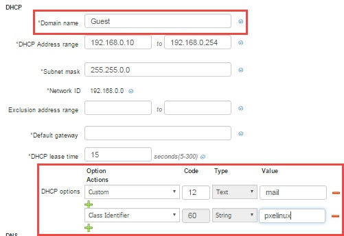
For example:
-
To set a hostname—from Option, choose Custom. In Code, type 15. Type automatically updates to Text. In Value, type the hostname (such as "mail" of mail.ise.com).
-
To set a TFTP Server Name—from Option, choose TFTP Server Name. Code and Type automatically update accordingly. In Value, type the TFTP server hostname.
Note |
Some of the DHCP options can not be manually entered because they are automatically defined for ISE. For example, Option 15 (Domain Name) cannot be defined as a custom option because the DHCP Domain name is already defined from this screen in a separate mandatory field and cannot be overridden. |
To enter multiple options click the plus sign under Actions.
Identity Management
These pages enable you to configure and manage identities in Cisco ISE.
Endpoints
These pages enable you to configure and manage endpoints that connect to your network.
Endpoint Settings
The following table describes the fields on the Endpoints page, which you can use to create endpoints and assign policies for endpoints. The navigation path for this page is: .
|
Fields |
Usage Guidelines |
|---|---|
|
MAC Address |
Enter the MAC address in hexadecimal format to create an endpoint statically. The MAC address is the device identifier for the interface that is connected to the Cisco ISE enabled network |
|
Static Assignment |
Check this check box when you want to create an endpoint statically in the Endpoints page and the status of static assignment is set to static. You can toggle the status of static assignment of an endpoint from static to dynamic or from dynamic to static. |
|
Policy Assignment |
(Disabled by default unless the Static Assignment is checked) Choose a matching endpoint policy from the Policy Assignment drop-down list. You can do one of the following:
|
|
Static Group Assignment |
(Disabled by default unless the Static group Assignment is checked) Check this check box when you want to assign an endpoint to an identity group statically. In you check this check box, the profiling service does not change the endpoint identity group the next time during evaluation of the endpoint policy for these endpoints, which were previously assigned dynamically to other endpoint identity groups. If you uncheck this check box, then the endpoint identity group is dynamic as assigned by the ISE profiler based on policy configuration. If you do not choose the Static Group Assignment option, then the endpoint is automatically assigned to the matching identity group the next time during evaluation of the endpoint policy. |
|
Identity Group Assignment |
Choose an endpoint identity group to which you want to assign the endpoint. You can assign an endpoint to an identity group when you create an endpoint statically, or when you do not want to use the Create Matching Identity Group option during evaluation of the endpoint policy for an endpoint. Cisco ISE includes the following system created endpoint identity groups:
|
Endpoint Import from LDAP Settings
The following table describes the fields on the Import from LDAP page, which you can use to import endpoints from an LDAP server. The navigation path for this page is: .
|
Fields |
Usage Guidelines |
||
|---|---|---|---|
|
Connection Settings |
|||
|
Host |
Enter the hostname, or the IP address of the LDAP server. |
||
|
Port |
Enter the port number of the LDAP server. You can use the default port 389 to import from an LDAP server, and the default port 636 to import from an LDAP server over SSL.
|
||
|
Enable Secure Connection |
Check the Enable Secure Connection check box to import from an LDAP server over SSL. |
||
|
Root CA Certificate Name |
Click the drop-down arrow to view the trusted CA certificates. The Root CA Certificate Name refers to the trusted CA certificate that is required to connect to an LDAP server. You can add (import), edit, delete, and export trusted CA certificates in Cisco ISE. |
||
|
Anonymous Bind |
Check the Anonymous Bind check box to enable the anonymous bind. You must enable either the Anonymous Bind check box, or enter the LDAP administrator credentials from the slapd.conf configuration file. |
||
|
Admin DN |
Enter the distinguished name (DN) configured for the LDAP administrator in the slapd.conf configuration file. Admin DN format example: cn=Admin, dc=cisco.com, dc=com |
||
|
Password |
Enter the password configured for the LDAP administrator in the slapd.conf configuration file. |
||
|
Base DN |
Enter the distinguished name of the parent entry. Base DN format example: dc=cisco.com, dc=com. |
||
|
Query Settings |
|||
|
MAC Address objectClass |
Enter the query filter, which is used for importing the MAC address. For example, ieee802Device. |
||
|
MAC Address Attribute Name |
Enter the returned attribute name for import. For example, macAddress. |
||
|
Profile Attribute Name |
Enter the name of the LDAP attribute. This attribute holds the policy name for each endpoint entry that is defined in the LDAP server. When you configure the Profile Attribute Name field, consider the following:
|
||
|
Time Out [seconds] |
Enter the time in seconds between 1 and 60 seconds. |
||
Groups
These pages enable you to configure and manage endpoint identity groups.
Endpoint Identity Group Settings
The following table describes the fields on the Endpoint Identity Groups page, which you can use to create an endpoint group. The navigation path for this page is: Administration > Identity Management > Groups > Endpoint Identity Groups.
|
Fields |
Usage Guidelines |
|---|---|
|
Name |
Enter the name of the endpoint identity group that you want to create. |
|
Description |
Enter a description for the endpoint identity group that you want to create. |
|
Parent Group |
Choose an endpoint identity group from the Parent Group drop-down list to which you want to associate the newly created endpoint identity group. |
External Identity Sources
These pages enable you to configure and manage external identity sources that contain user data that Cisco ISE uses for authentication and authorization.
LDAP Identity Source Settings
The following table describes the fields on the LDAP Identity Sources page, which you can use to create an LDAP instance and connect to it. The navigation path for this page is: .
LDAP General Settings
The following table describes the fields in the General tab.
|
Fields |
Usage Guidelines |
||
|---|---|---|---|
|
Name |
Enter a name for the LDAP instance. This value is used in searches to obtain the subject DN and attributes. The value is of type string and the maximum length is 64 characters. |
||
|
Description |
Enter a description for the LDAP instance. This value is of type string, and has a maximum length of 1024 characters. |
||
|
Schema |
You can choose any one of the following built-in schema types or create a custom schema:
|
||
|
|||
|
Subject Objectclass |
Enter a value to be used in searches to obtain the subject DN and attributes. The value is of type string and the maximum length is 256 characters. |
||
|
Subject Name Attribute |
Enter the name of the attribute containing the username in the request. The value is of type string and the maximum length is 256 characters. |
||
|
Group Name Attribute |
Enter CN or DN or any supported attribute in the Group Name Attribute field.
|
||
|
Certificate Attribute |
Enter the attribute that contains the certificate definitions. For certificate-based authentication, these definitions are used to validate certificates that are presented by clients. |
||
|
Group Objectclass |
Enter a value to be used in searches to specify the objects that are recognized as groups. The value is of type string and the maximum length is 256 characters. |
||
|
Group Map Attribute |
Specifies the attribute that contains the mapping information. This attribute can be a user or group attribute based on the reference direction that is chosen. |
||
|
Subject Objects Contain Reference To Groups |
Click this radio button if the subject objects contain an attribute that specifies the group to which they belong. |
||
|
Group Objects Contain Reference To Subjects |
Click this radio button if the group objects contain an attribute that specifies the subject. This value is the default value. |
||
|
Subjects in Groups Are Stored in Member Attribute As |
(Only available when you select the Group Objects Contain Reference To Subjects radio button) Specifies how members are sourced in the group member attribute and defaults to the DN. |
||
|
User Info Attributes |
By default, predefined attributes are used to collect user information (such as, first name, last name, email, telephone, locality, and so on) for the following built-in schema types:
If you edit the attributes of the predefined schema, Cisco ISE automatically creates a Custom schema. You can also select the Custom option from the Schema drop-down list to edit the user information attributes based on your requirements. |
||
LDAP Connection Settings
The following table describes the fields in the Connection Settings tab.
|
Fields |
Usage Guidelines |
|---|---|
|
Enable Secondary Server |
Check this option to enable the secondary LDAP server to be used as a backup if the primary LDAP server fails. If you check this check box, you must enter configuration parameters for the secondary LDAP server. |
|
Primary and Secondary Servers |
|
|
Hostname/IP |
Enter the IP address or DNS name of the machine that is running the LDAP software. The hostname can contain from 1 to 256 characters or a valid IP address expressed as a string. The only valid characters for hostnames are alphanumeric characters (a to z, A to Z, 0 to 9), the dot (.), and the hyphen (-). |
|
Port |
Enter the TCP/IP port number on which the LDAP server is listening. Valid values are from 1 to 65,535. The default is 389, as stated in the LDAP specification. If you do not know the port number, you can find this information from the LDAP server administrator. |
|
Specify server for each ISE node |
Check this check box to configure primary and secondary LDAP server hostnames/IP and their ports for each PSN. When this option is enabled, a table listing all the nodes in the deployment is displayed. You need to select the node and configure the primary and secondary LDAP server hostname/IP and their ports for the selected node. |
|
Access |
Anonymous Access—Click to ensure that searches on the LDAP directory occur anonymously. The server does not distinguish who the client is and will allow the client read access to any data that is configured as accessible to any unauthenticated client. In the absence of a specific policy permitting authentication information to be sent to a server, a client should use an anonymous connection. Authenticated Access—Click to ensure that searches on the LDAP directory occur with administrative credentials. If so, enter information for the Admin DN and Password fields. |
|
Admin DN |
Enter the DN of the administrator. The Admin DN is the LDAP account that has permission to search all required users under the User Directory Subtree and to search groups. If the administrator specified does not have permission to see the group name attribute in searches, group mapping fails for users who are authenticated by that LDAP server. |
|
Password |
Enter the LDAP administrator account password. |
|
Secure Authentication |
Click to use SSL to encrypt communication between Cisco ISE and the primary LDAP server. Verify that the Port field contains the port number used for SSL on the LDAP server. If you enable this option, you must choose a root CA. |
|
LDAP Server Root CA |
Choose a trusted root certificate authority from the drop-down list to enable secure authentication with a certificate. |
|
Server Timeout |
Enter the number of seconds that Cisco ISE waits for a response from the primary LDAP server before determining that the connection or authentication with that server has failed. Valid values are 1 to 99. The default is 10. |
|
Max. Admin Connections |
Enter the maximum number of concurrent connections (greater than 0) with LDAP administrator account permissions that can run for a specific LDAP configuration. These connections are used to search the directory for users and groups under the User Directory Subtree and the Group Directory Subtree. Valid values are 1 to 99. The default is 20. |
|
Force reconnect every N seconds |
Check this check box and enter the desired value in the Seconds text box to force the server to renew LDAP connection at the specified time interval. The valid range is from 1 to 60 minutes. |
|
Test Bind to Server |
Click to test and ensure that the LDAP server details and credentials can successfully bind. If the test fails, edit your LDAP server details and retest. |
|
Failover |
|
|
Always Access Primary Server First |
Click this option if you want Cisco ISE to always access the primary LDAP server first for authentications and authorizations. |
|
Failback to Primary Server After |
If the primary LDAP server that Cisco ISE attempts to contact cannot be reached, Cisco ISE attempts to contact the secondary LDAP server. If you want Cisco ISE to use the primary LDAP server again, click this option and enter a value in the text box. |
LDAP Directory Organization Settings
The following table describes the fields in the Directory Organization tab.
|
Fields |
Usage Guidelines |
||
|---|---|---|---|
|
Subject Search Base |
Enter the DN for the subtree that contains all subjects. For example: o=corporation.com If the tree containing subjects is the base DN, enter: o=corporation.com or dc=corporation,dc=com as applicable to your LDAP configuration. For more information, refer to your LDAP database documentation. |
||
|
Group Search Base |
Enter the DN for the subtree that contains all groups. For example: ou=organizational unit, ou=next organizational unit, o=corporation.com If the tree containing groups is the base DN, type: o=corporation.com or dc=corporation,dc=com as applicable to your LDAP configuration. For more information, refer to your LDAP database documentation. |
||
|
Search for MAC Address in Format |
Enter a MAC Address format for Cisco ISE to use for search in the LDAP database. MAC addresses in internal identity sources are sourced in the format xx-xx-xx-xx-xx-xx. MAC addresses in LDAP databases can be sourced in different formats. However, when Cisco ISE receives a host lookup request, Cisco ISE converts the MAC address from the internal format to the format that is specified in this field. Use the drop-down list to enable searching for MAC addresses in a specific format, where <format> can be any one of the following:
The format you choose must match the format of the MAC address sourced in the LDAP server. |
||
|
Strip Start of Subject Name Up To the Last Occurrence of the Separator |
Enter the appropriate text to remove domain prefixes from usernames. If, in the username, Cisco ISE finds the delimiter character that is specified in this field, it strips all characters from the beginning of the username through the delimiter character. If the username contains more than one of the characters that are specified in the <start_string> box, Cisco ISE strips characters through the last occurrence of the delimiter character. For example, if the delimiter character is the backslash (\) and the username is DOMAIN\user1, Cisco ISE submits user1 to an LDAP server.
|
||
|
Strip End of Subject Name from the First Occurrence of the Separator |
Enter the appropriate text to remove domain suffixes from usernames. If, in the username, Cisco ISE finds the delimiter character that is specified in this field, it strips all characters from the delimiter character through the end of the username. If the username contains more than one of the characters that are specified in this field, Cisco ISE strips characters starting with the first occurrence of the delimiter character. For example, if the delimiter character is @ and the username is user1@domain, then Cisco ISE submits user1 to the LDAP server.
|
LDAP Group Settings
|
Fields |
Usage Guidelines |
|---|---|
|
Add |
Choose Add > Add Group to add a new group or choose Add > Select Groups From Directory to select the groups from the LDAP directory. If you choose to add a group, enter a name for the new group. If you are selecting from the directory, enter the filter criteria, and click Retrieve Groups. Check the check boxes next to the groups that you want to select and click OK. The groups that you have selected will appear in the Groups page. |
LDAP Attribute Settings
|
Fields |
Usage Guidelines |
|---|---|
|
Add |
Choose Add > Add Attribute to add a new attribute or choose Add > Select Attributes From Directory to select attributes from the LDAP server. If you choose to add an attribute, enter a name for the new attribute. If you are selecting from the directory, enter the username and click Retrieve Attributes to retrieve the user’s attributes. Check the check boxes next to the attributes that you want to select, and then click OK. |
LDAP Advanced Settings
The following table describes the field in the Advanced Settings tab.
|
Fields |
Usage Guidelines |
|---|---|
|
Enable Password Change |
Check this check box to enable the user to change the password in case of password expiry or password reset while using PAP protocol for device admin and RADIUS EAP-GTC protocol for network access. User authentication fails for the unsupported protocols. This option also enables the user to change the password on their next login. |
RADIUS Token Identity Sources Settings
| Fields | Usage Guidelines |
|---|---|
|
Name |
Enter a name for the RADIUS token server. The maximum number of characters allowed is 64. |
|
Description |
Enter a description for the RADIUS token server. The maximum number of characters is 1024. |
|
SafeWord Server |
Check this check box if your RADIUS identity source is a SafeWord server. |
|
Enable Secondary Server |
Check this check box to enable the secondary RADIUS token server for Cisco ISE to use as a backup in case the primary fails. If you check this check box, you must configure a secondary RADIUS token server. |
|
Always Access Primary Server First |
Click this radio button if you want Cisco ISE to always access the primary server first. |
|
Fallback to Primary Server after |
Click this radio button to specify the amount of time in minutes that Cisco ISE can authenticate using the secondary RADIUS token server if the primary server cannot be reached. After this time elapses, Cisco ISE reattempts to authenticate against the primary server. |
| Primary Server | |
|
Host IP |
Enter the IP address of the primary RADIUS token server. This field can take as input a valid IP address that is expressed as a string. Valid characters that are allowed in this field are numbers and dot (.). |
|
Shared Secret |
Enter the shared secret that is configured on the primary RADIUS token server for this connection. |
|
Authentication Port |
Enter the port number on which the primary RADIUS token server is listening. |
|
Server Timeout |
Specify the time in seconds that Cisco ISE should wait for a response from the primary RADIUS token server before it determines that the primary server is down. |
|
Connection Attempts |
Specify the number of attempts that Cisco ISE should make to reconnect to the primary server before moving on to the secondary server (if defined) or dropping the request if a secondary server is not defined. |
| Secondary Server | |
|
Host IP |
Enter the IP address of the secondary RADIUS token server. This field can take as input a valid IP address that is expressed as a string. Valid characters that are allowed in this field are numbers and dot (.). |
|
Shared Secret |
Enter the shared secret configured on the secondary RADIUS token server for this connection. |
|
Authentication Port |
Enter the port number on which the secondary RADIUS token server is listening. Valid values are from 1 to 65,535. The default is 1812. |
|
Server Timeout |
Specify the time in seconds that Cisco ISE should wait for a response from the secondary RADIUS token server before it determines that the secondary server is down. |
|
Connection Attempts |
Specify the number of attempts that Cisco ISE should make to reconnect to the secondary server before dropping the request. |
RSA SecurID Identity Source Settings
RSA Prompt Settings
The following table describes the fields in the RSA Prompts tab.
|
Fields |
Usage Guidelines |
|---|---|
|
Enter Passcode Prompt |
Enter a text string to obtain the passcode. |
|
Enter Next Token Code |
Enter a text string to request the next token. |
|
Choose PIN Type |
Enter a text string to request the PIN type. |
|
Accept System PIN |
Enter a text string to accept the system-generated PIN. |
|
Enter Alphanumeric PIN |
Enter a text string to request an alphanumeric PIN. |
|
Enter Numeric PIN |
Enter a text string to request a numeric PIN. |
|
Re-enter PIN |
Enter a text string to request the user to re-enter the PIN. |
RSA Message Settings
The following table describes the fields in the RSA Messages tab.
|
Fields |
Usage Guidelines |
|---|---|
|
Display System PIN Message |
Enter a text string to label the system PIN message. |
|
Display System PIN Reminder |
Enter a text string to inform the user to remember the new PIN. |
|
Must Enter Numeric Error |
Enter a message that instructs users to enter only numbers for the PIN. |
|
Must Enter Alpha Error |
Enter a message that instructs users to enter only alphanumeric characters for PINs. |
|
PIN Accepted Message |
Enter a message that the users see when their PIN is accepted by the system. |
|
PIN Rejected Message |
Enter a message that the users see when the system rejects their PIN. |
|
User Pins Differ Error |
Enter a message that the users see when they enter an incorrect PIN. |
|
System PIN Accepted Message |
Enter a message that the users see when the system accepts their PIN. |
|
Bad Password Length Error |
Enter a message that the users see when the PIN that they specify does not fall within the range specified in the PIN length policy. |
Network Resources
Network Devices
These pages enable you to add and manage network devices.
Note |
IPv4 and IPv6 are now supported for network device (TACACS and RADIUS) configuration and for external RADIUS server configuration. When entering an IPv4 address, you can use ranges and subnet masks. Ranges are not supported for IPv6. |
Network Device Definition Settings
The following table describes the fields in the Network Devices page, which you can use to configure a network access device in Cisco ISE. The navigation path for this page is: .
Network Device Settings
The following table describes the fields in the Network Device section.
|
Fields |
Description |
||
|---|---|---|---|
|
Name |
Enter the name for the network device. You can provide a descriptive name to the network device that can be different from the hostname of the device. The device name is a logical identifier.
|
||
|
Description |
Enter the description for the device. |
||
|
IP Address/IP Ranges |
Choose one of the following:
The following are the guidelines that must be followed while defining the IP addresses and subnet masks or IP address ranges:
|
||
|
Device Type |
Click the drop-down list to select the vendor of the network device. You can use the tool tip next to the drop-down list to see the flows and services that the selected vendor's network devices support, as well as the RADIUS CoA port and type of URL redirect used by the device. These attributes are defined in the device type's network device profile. |
||
|
Model Name |
Click the drop-down list to choose the device model, for example. You can use the model name as one of the parameters while checking for conditions in rule-based policies. This attribute is present in the device dictionary. |
||
|
Software Version |
Click the drop-down list d to choose the version of the software running on the network device. You can use the software version as one of the parameters while checking for conditions in rule-based policies. This attribute is present in the device dictionary. |
||
|
Network Device Group |
Click the Location and Device Type drop-down lists to choose a location and device type that can be associated with the network device. If you do not specifically assign a device to a group when you configure it, it becomes a part of the default device groups (root NDGs), which is All Locations by location and All Device Types by device type and the default device groups (root NDGs) are assigned. For example, All Locations and All Device Groups. |
RADIUS Authentication Settings
The following table describes the fields in the RADIUS Authentication Settings section.
|
Fields |
Usage Guidelines |
||
|---|---|---|---|
|
RADIUS UDP Settings |
|||
|
Protocol |
Displays RADIUS as the selected protocol. |
||
|
Shared Secret |
Enter the shared secret for the network device. The shared secret is the key that you have configured on the network device using the radius-host command with the pac option.
|
||
|
Use Second Shared Secret |
Specify two shared secrets (keys) to be used by the network device and Cisco ISE.
|
||
|
CoA Port |
Specify the port to be used for RADIUS CoA. The default CoA port for the device is defined in the network device profile.
|
||
|
RADIUS DTLS Settings |
|||
|
DTLS Required |
If you enable this option, Cisco ISE will process only the DTLS requests from this device. If this option is disabled, Cisco ISE will process both UDP and DTLS requests from this device. RADIUS DTLS provides improved security for SSL tunnel establishment and RADIUS communication. |
||
|
Shared Secret |
Displays the shared secret used for RADIUS DTLS. This value is fixed and used to compute the MD5 integrity checks. |
||
|
CoA Port |
Specify the port to be used for RADIUS DTLS CoA. |
||
|
Issuer CA of ISE Certificates for CoA |
Select the Certificate Authority to be used for RADIUS DTLS CoA from the drop-down list. |
||
|
DNS Name |
Enter the DNS name of the network device. If the Enable RADIUS/DTLS Client Identity Verification option is enabled under RADIUS settings, Cisco ISE compares this DNS name with the DNS name that is specified in the client certificate to verify the identity of the network device. |
||
|
General Settings |
|||
|
Enable KeyWrap |
Check this check box only when supported on the network device, which increases RADIUS security via an AES KeyWrap algorithm.
|
||
|
Key Encryption Key |
(Only appears when you enable KeyWrap) Enter an encryption key that is used for session encryption (secrecy). |
||
|
Message Authenticator Code Key |
(Only appears when you enable KeyWrap) Enter the key that is used for keyed Hashed Message Authentication Code (HMAC) calculation over RADIUS messages. |
||
|
Key Input Format |
Choose one of the following formats:
You can specify the key input format that you want to use to enter the Cisco ISE FIPS encryption key, so that it matches the configuration that is available on the WLC. (The value that you specify must be the correct [full] length for the key, and shorter values are not permitted.) |
||
TACACS+ Authentication Settings
The following table describes the fields on the Network Devices page, which you can use to configure TACACS+ authentication settings for a network device. The navigation path is:
-
(For Network Devices) .
-
(For Default Devices) . See the Default Network Device Definition in Cisco ISE section in Cisco ISE Admin Guide: Secure Wired Access for more information.
|
Field |
Usage Guidelines |
|---|---|
|
Shared Secret |
A string of text assigned to a network device when TACACS+ protocol is enabled. A user must enter the text before the network device authenticates a username and password. The connection is rejected until the user supplies the shared secret. This is not a mandatory field. |
|
Retired Shared Secret is Active |
Displayed when the retirement period is active. |
|
Retire |
Retires an existing shared secret instead of ending it. When you click Retire, a message box is displayed. You can either click Yes or No. |
|
Remaining Retired Period |
(Available only if you select Yes in the above message box) Displays the default value specified in the following navigation path: You can change the default values. This allows a new shared secret to be entered and the old shared secret will remain active for the specified number of days. |
|
End |
(Available only if you select Yes in the above message box) Ends the retirement period and terminates the old shared secret. |
|
Enable Single Connect Mode |
Check to use a single TCP connection for all TACACS+ communication with the network device. Choose one of the following:
|
SNMP Settings
The following table describes the fields in the SNMP Settings section.
|
Fields |
Usage Guidelines |
||
|---|---|---|---|
|
SNMP Version |
Choose an SNMP version from the Version drop-down list to be used for requests. Version includes the following:
|
||
|
SNMP RO Community |
(Only for SNMP Versions 1 and 2c when selected) Enter the Read Only Community string that provides Cisco ISE with a particular type of access to the device.
|
||
|
SNMP Username |
(Only for SNMP Version 3) Enter SNMP username. |
||
|
Security Level |
(Only for SNMP Version 3) Choose the security level from the following:
|
||
|
Auth Protocol |
(Only for SNMP Version 3 when the security levels Auth and Priv are selected) Choose the authentication protocol that you want the network device to use. Authentication Protocol includes one of the following for security levels of Auth and Priv:
|
||
|
Auth Password |
(Only for SNMP Version 3 when the security levels Auth and Priv are selected) Enter the authentication key that must be at least 8 characters in length. Click Show to display the Auth Password that is already configured for the device.
|
||
|
Privacy Protocol |
(Only for SNMP Version 3 when the security level Priv is selected) Choose the privacy protocol that you want the network device to use. Privacy Protocols are one of the following:
|
||
|
Privacy Password |
(Only for SNMP Version 3 when the security level Priv is selected) Enter the privacy key. Click Show to display the Privacy Password that is already configured for the device.
|
||
|
Polling Interval |
Enter the polling interval in seconds. The default is 3600 seconds. |
||
|
Link Trap Query |
Check this check box to receive and interpret linkup and linkdown notifications received through the SNMP Trap. |
||
|
Mac Trap Query |
Check this check box to receive and interpret MAC notifications received through the SNMP Trap |
||
|
Originating Policy Service Node |
Indicates which ISE server to be used to poll for SNMP data. By default, it is automatic, but you can overwrite the setting by assigning different values. |
Advanced TrustSec Settings
The following table describes the fields in the Advanced TrustSec Settings section.
|
Fields |
Usage Guidelines |
|---|---|
|
TrustSec Device Notification and Updates Settings |
|
|
Use Device ID for TrustSec Identification |
Check this check box if you want the device name to be listed as the device identifier in the Device ID field. |
|
Device ID |
You can enter the device ID in this field only if you have not checked the Use Device ID for TrustSec Identification check box. |
|
Password |
Enter the password that you have configured on the TrustSec device CLI to authenticate the TrustSec device. Click Show to display the password that is used to authenticate the TrustSec device. |
|
Download Environment Data Every <...> |
Specify the time interval at which the device must download its environment data from Cisco ISE. You can specify the time in seconds, minutes, hours, weeks, or days. The default value is 1 day. |
|
Download Peer Authorization Policy Every <...> |
Specify the time interval at which the device must download the peer authorization policy from Cisco ISE. You can specify the time in seconds, minutes, hours, weeks, or days. The default value is 1 day. |
|
Reauthentication Every <...> |
Specify the time interval at which the device reauthenticates itself against Cisco ISE after the initial authentication. You can configure the time interval in seconds, minutes, hours, weeks or days. For example, if you enter 1000 seconds, the device will authenticate itself against Cisco ISE every 1000 seconds. The default value is 1 day. |
|
Download SGACL Lists Every <...> |
Specify the time interval at which the device downloads SGACL lists from Cisco ISE. You can configure the time interval in seconds, minutes, hours, weeks or days. The default value is 1 day. |
|
Other TrustSec Devices to Trust This Device (TrustSec Trusted) |
Check this check box if you want all the peer devices to trust this TrustSec device. If you uncheck this check box, the peer devices do not trust this device, and all the packets that arrive from this device are colored or tagged accordingly. |
|
Send Configuration Changes to Device |
Check this check box if you want Cisco ISE to send TrustSec configuration changes to the TrustSec device using CoA or CLI (SSH). |
|
Using CoA |
Select this option if you want Cisco ISE to send the configuration changes to the TrustSec device using CoA. |
|
Send From |
Choose the ISE node from which the configuration changes must be sent to the TrustSec device from this drop-down list. You can select the PAN or PSN node. If the PSN node that you selected is down, the configuration changes are sent to the TrustSec device using the PAN. |
|
Test Connection |
You can use this option to test the connectivity between the TrustSec device and the selected ISE node (PAN or PSN node). |
|
Using CLI (SSH) |
Select this option if you want Cisco ISE to send the configuration changes to the TrustSec device using CLI (using the SSH connection). For more information, see the Push Configuration Changes to Non-CoA Supporting Devices section in Cisco ISE Admin Guide: Segmentation . |
|
SSH Key |
To use this feature, open an SSHv2 tunnel from Cisco ISE to the network device, and use the device's CLI to retrieve the SSH key. You must copy this key and paste it in the SSH Key field for validation. For more information, see the SSH Key Validation section in Cisco ISE Admin Guide: Segmentation . |
|
Device Configuration Deployment Settings |
|
|
Include this device when deploying Security Group Tag Mapping Updates |
Check this check box if you want the TrustSec device to obtain the IP-SGT mappings using device interface credentials. |
|
EXEC Mode Username |
Enter the username that you use to log in to the TrustSec device. |
|
EXEC Mode Password |
Enter the device password. |
|
Enable Mode Password |
(Optional) Enter the enable password that is used to edit the configuration of the TrustSec device in privileged mode. |
|
Out Of Band TrustSec PAC Display |
|
|
Issue Date |
Displays the issuing date of the last TrustSec PAC that has been generated by Cisco ISE for the TrustSec device. |
|
Expiration Date |
Displays the expiration date of the last TrustSec PAC that has been generated by Cisco ISE for the TrustSec device. |
|
Issued By |
Displays the name of the issuer (a TrustSec administrator) of the last TrustSec PAC that has been generated by Cisco ISE for the TrustSec device. |
|
Generate PAC |
Click this option to generate the out-of-band TrustSec PAC for the TrustSec device. |
Default Network Device Definition Settings
The following table describes the fields in the Default Network device page, which allows you to configure a default network device that Cisco ISE can use for RADIUS or TACACS+ authentication. Choose one of the navigation paths:
|
Fields |
Usage Guidelines |
||
|---|---|---|---|
|
Default Network Device Status |
Choose Enable from the Default Network Device Status drop-down list to enable the default network device definition.
|
||
|
Device Profile |
Displays Cisco as the default device vendor. |
||
|
RADIUS Authentication Settings |
|||
|
Enable RADIUS |
Check this check box if you want to enable RADIUS authentication for the device. |
||
|
RADIUS UDP Settings |
|||
|
Shared Secret |
Enter a shared secret. The shared secret can be up to 127 characters in length. The shared secret is the key that you have configured on the network device using the radius-host command with the pac option.
|
||
|
RADIUS DTLS Settings |
|||
|
DTLS Required |
If you enable this option, Cisco ISE will process only the DTLS requests from this device. If this option is disabled, Cisco ISE will process both UDP and DTLS requests from this device. RADIUS DTLS provides improved security for SSL tunnel establishment and RADIUS communication. |
||
|
Shared Secret |
Displays the shared secret used for RADIUS DTLS. This value is fixed and is used to compute the MD5 integrity checks. |
||
|
Issuer CA of ISE Certificates for CoA |
Select the Certificate Authority to be used for RADIUS DTLS CoA from the drop-down list. |
||
|
General Settings |
|||
|
Enable KeyWrap |
Check this check box only when supported on the network device, which increases RADIUS security via an AES KeyWrap algorithm. When you run Cisco ISE in FIPS mode, you must enable KeyWrap on the network device. |
||
|
Key Encryption Key |
Enter an encryption key that is used for session encryption (secrecy) when you enable KeyWrap. |
||
|
Message Authenticator Code Key |
Enter the key that is used for keyed Hashed Message Authentication Code (HMAC) calculation over RADIUS messages when you enable KeyWrap. |
||
|
Key Input Format |
Choose one of the following formats:
You can specify the key input format that you want to use to enter the Cisco ISE FIPS encryption key, so that it matches the configuration that is available on the WLC. The value that you specify must be the correct (full) length for the key. Shorter values are not permitted. |
||
|
TACACS Authentication Settings |
|||
|
Shared Secret |
A string of text assigned to a network device when TACACS+ protocol is enabled. A user must enter the text before the network device authenticates a username and password. The connection is rejected until the user supplies the shared secret. |
||
|
Retired Shared Secret is Active |
Displayed when the retirement period is active. |
||
|
Retire |
Retires an existing shared secret instead of ending it. When you click Retire, a message box is displayed. You can either click Yes or No. |
||
|
Remaining Retired Period |
(Available only if you select Yes in the above message box) Displays the default value specified in the following navigation path: You can change the default values. This allows a new shared secret to be entered and the old shared secret will remain active for the specified number of days. |
||
|
End |
(Available only if you select Yes in the above message box) Ends the retirement period and terminates the old shared secret. |
||
|
Enable Single Connect Mode |
Check to use a single TCP connection for all TACACS+ communication with the network device. Choose one of the following:
|
||
Device Security Settings
Specify the minimum length for the RADIUS shared secret. For new installation and upgraded deployment, by default, this value is 4 characters. For the RADIUS server, best practice is to have 22 characters.
Note |
The length of the shared secret entered in the Network Devices page must be equal to or greater than the value configured in the Minimum RADIUS Shared Secret Length field in the Device Security Settings page. |
Network Device Import Settings
The following table describes the fields on the Network Device Import Page, which you can use to import network device details into Cisco ISE. The navigation path for this page is: .
|
Fields |
Usage Guidelines |
|---|---|
|
Generate a Template |
Click this link to create a comma-separated value (.csv) template file. You must update the template with network devices information in the same format, and save it locally to import those network devices into any Cisco ISE deployment. |
|
File |
Click Browse to the location of the comma-separated value file that you might have created or previously exported from any Cisco ISE deployment. You can import network devices in another Cisco ISE deployment with new and updated network devices information using import. |
|
Overwrite Existing Data with New Data |
Check this check box if you want Cisco ISE to replace existing network devices with the devices in your import file. If you do not check this check box, new network device definitions that are available in the import file are added to the network device repository. Duplicate entries are ignored. |
|
Stop Import on First Error |
Check this check box if you want Cisco ISE to discontinue import when it encounters an error during import, but Cisco ISE imports network devices until that time of an error. If this check box is not checked and an error is encountered, the error is reported, and Cisco ISE continues to import devices. |
Network Device Groups
These pages enable you to configure and manage network device groups.
Network Device Group Settings
The following table describes the fields on the Network Device Groups Page, which you can use to create network device groups. The navigation path for this page is: .
You can also create network device groups in the page.
|
Fields |
Usage Guidelines |
|---|---|
|
Name |
Enter the name for the root Network Device Group (NDG). For all subsequent child network device groups under the root NDG, enter the name of the new network device group. You can have a maximum of six nodes in the NDG hierarchy, including the root node. Each NDG name can have a maximum of 32 characters. |
|
Description |
Enter the description for the root or the child Network Device Group. |
|
Parent Group |
You can select an already existing group as the parent group or add this new group as a root group. |
Network Device Group Import Settings
The following table describes the fields on the Network Device Group Import Page, which you can use to import network device groups into Cisco ISE. The navigation path for this page is: .
|
Fields |
Usage Guidelines |
|---|---|
|
Generate a Template |
Click this link to create a comma-separated value (.csv) template file. You must update the template with network device groups information in the same format, and save it locally to import those network device groups into any Cisco ISE deployment. |
|
File |
Click Browse to the location of the comma-separated value file that you might have created or previously exported from any Cisco ISE deployment. You can import network device groups in another Cisco ISE deployment with new and updated network device groups information using import. |
|
Overwrite Existing Data with New Data |
Check this check box if you want Cisco ISE to replace existing network device groups with the device groups in your import file. If you do not check this check box, new network device group that are available in the import file are added to the network device group repository. Duplicate entries are ignored. |
|
Stop Import on First Error |
Check this check box if you want Cisco ISE to discontinue import when it encounters an error during import, but Cisco ISE imports network device groups until that time of an error. If this check box is not checked and an error is encountered, the error is reported, and Cisco ISE continues to import device groups. |
Network Device Profiles Settings
The following table describes the fields on the Network Device Profiles page, which you can use to configure the default settings for a type of network device from a specific vendor, such as the device's support for protocols, redirect URLs, and CoA settings. You then use the profile to define specific network devices.
The navigation path for this page is: .
Network Device Profile Settings
The following table describes the fields in the Network Device Profile section.
|
Fields |
Description |
|---|---|
|
Name |
Enter the name for the network device profile. |
|
Description |
Enter the description for the network device profile. |
|
Icon |
Select the icon to use for the network device profile. This icon will default to the icon for the vendor that you select. The icon you select must be a 16 x 16 PNG file. |
|
Vendor |
Select the vendor of the network device profile. The vendors available for selection are Cisco, Aruba, HP, Motorola, Brocade, Alcatel, and Other. |
|
Supported Protocols |
|
|
RADIUS |
Check this check box if this network device profile supports RADIUS. |
|
TACACS+ |
Check this check box if this network device profile supports TACACS+. |
|
TrustSec |
Check this check box if this network device profile supports TrustSec. |
|
RADIUS Dictionaries |
Select one or more RADIUS dictionaries supported by this profile. Import any vendor-specific RADIUS dictionaries before you create the profile. |
Authentication/Authorization Template Settings
The following table describes the fields in the Authentication/Authorization section.
|
Fields |
Description |
|---|---|
|
Flow Type Conditions |
Cisco ISE supports 802.1X, MAC authentication bypass (MAB), and browser-based Web authentication login for basic user authentication and access via both wired and wireless networks. Check the check boxes for the authentication logins that this type of network device supports. It could be one or more of the following:
After you check the authentication logins that the network device profile supports, specify the conditions for the login. |
|
Attribute Aliasing |
Check the SSID check box to use the device's Service Set Identifier (SSID) as the friendly name in policy rules. This allows you to create a consistent name to use in policy rules and it will work for multiple devices. |
|
Host Lookup (MAB) |
|
|
Process Host Lookup |
Check this check box to define the protocols for host lookup used by the network device profile. Network devices from different vendors perform MAB authentication differently. Depending on the device type, check the Check Password check, the Checking Calling-Station-Id equals MAC Address check box, or both, for the protocol you are using. |
|
Via PAP/ASCII |
Check this check box to configure Cisco ISE to detect a PAP request from the network device profile as a Host Lookup request. |
|
Via CHAP |
Check this check box to configure Cisco ISE to detect this type of request from the network devices as a Host Lookup request. This option enables CHAP authentication. CHAP uses a challenge-response mechanism with password encryption. CHAP does not work with Microsoft Active Directory. |
|
Via EAP-MD5 |
Check this check box to enable EAP-based MD5 hashed authentication for the network device profile. |
Permissions Template Settings
You can define the VLAN and ACL permissions that will be used for this network device profile. After the profile is saved, Cisco ISE automatically generates authorization profiles for each configured permission. The following table describes the fields in the Permissions section.
|
Fields |
Description |
|---|---|
|
Set VLAN |
Check this check box to set the VLAN permissions for this network device profile. Choose of the following options:
|
|
Set ACL |
Check this check box to select the RADIUS attribute to set for the ACL on the network device profile. |
Change of Authorization (CoA) Template Settings
This template defines how the CoA is sent to this type of network device. The following table describes the fields in the Change of Authorization (CoA) section.
|
Fields |
Definition |
|---|---|
|
CoA by |
Select whether to deliver the CoA packets to the network device profile by RADIUS, by SNMP or not at all. |
|
CoA by RADIUS |
|
|
Default CoA Port |
The port to send the RADIUS CoA. By default, this is port 1700 for Cisco devices and port 3799 for devices from a non-Cisco vendor. You can override this on the Network Device page. |
|
Timeout Interval |
The number of seconds that Cisco ISE waits for a response after sending the CoA. |
|
Retry Count |
The number of times Cisco ISE attempts to send the CoA after the first timeout. |
|
Disconnect |
Select how to send a disconnect request to these devices.
|
|
Re-authenticate |
Select how to send a reauthentication request to the network devices. This is currently supported only by Cisco devices.
|
|
CoA Push |
If the network devices do not support Cisco's TrustSec CoA feature, select this option to allow Cisco ISE to push a configuration change to the device. |
|
CoA by SNMP |
|
|
Timeout Interval |
The number of seconds that Cisco ISE waits for a response after sending the CoA. |
|
Retry Count |
The number of times that Cisco ISE attempts to send a CoA. |
|
NAD Port Detection |
Relevant RADIUS attribute is currently the only option. |
|
Relevant RADIUS Attribute |
Select how to detect the NAD port.
|
|
Disconnect |
Select how to send a disconnect request to these devices.
|
Redirect Template Settings
The network devices can redirect a client's HTTP requests if it's configured as part of the authorization profile. This template specifies whether this network device profile supports URL redirect. You will use the URL parameter names specific to the device type.
The following table describes the fields in the Redirect section.
|
Fields |
Definition |
|---|---|
|
Type |
Select whether the network device profile supports a static or dynamic URL redirect. If your device supports neither, select Not Supported and set up a VLAN from . |
|
Redirect URL Parameter Names |
|
|
Client IP Address |
Enter the parameter name that the network devices use for a client's IP address. |
|
Client MAC Address |
Enter the parameter name that the network devices use for a client's MAC address. |
|
Originating URL |
Enter the parameter name that the network devices use for the originating URL. |
|
Session ID |
Enter the parameter name that the network devices use for the session ID. |
|
SSID |
Enter the parameter name that the network devices use for the Service Set Identifier (SSID). |
|
Dynamic URL Parameters |
|
|
Parameter |
When you select to use a Dynamic URL for redirection, you will need to specify how these network devices create the redirect URL. You can also specify whether the redirect URL uses the session ID or client MAC address. |
Advanced Settings
You can use the Network Device Profile to generate a number of policy elements to make it easy to use a network device in policy rules. These elements include compound conditions, authorization profiles, and allowed protocols.
Click the Generate Policy Elements button to create these elements.
External RADIUS Server Settings
The following table describes the fields on the External RADIUS Server page, which you can use to configure a RADIUS server. For Cisco ISE to act as a RADIUS server, you must configure it in this page. The navigation path for this page is: .
|
Fields |
Usage Guidelines |
||
|---|---|---|---|
|
Name |
Enter the name of the external RADIUS server. |
||
|
Description |
Enter a description of the external RADIUS server. |
||
|
Host IP |
Enter the IP address of the external RADIUS server.
|
||
|
Shared Secret |
Enter the shared secret between Cisco ISE and the external RADIUS server that is used for authenticating the external RADIUS server. A shared secret is an expected string of text that a user must provide to enable the network device to authenticate a username and password. The connection is rejected until the user supplies the shared secret. The shared secret can be up to 128 characters in length. |
||
|
Enable KeyWrap |
Enable this option to increase the RADIUS protocol security via an AES KeyWrap algorithm, to help enable FIPS 140-2 compliance in Cisco ISE. |
||
|
Key Encryption Key |
(Only if you check the Enable Key Wrap check box) Enter a key to be used for session encryption (secrecy). |
||
|
Message Authenticator Code Key |
(Only if you check the Enable Key Wrap check box) Enter a key to be used for keyed HMAC calculation over RADIUS messages. |
||
|
Key Input Format |
Specify the format you want to use to enter the Cisco ISE encryption key, so that it matches the configuration that is available on the WLAN controller. (The value you specify must be the correct [full] length for the key as defined below—shorter values are not permitted.)
|
||
|
Authentication Port |
Enter the RADIUS authentication port number. The valid range is from 1 to 65535. The default is 1812. |
||
|
Accounting Port |
Enter the RADIUS accounting port number. The valid range is from 1 to 65535. The default is 1813. |
||
|
Server Timeout |
Enter the number of seconds that the Cisco ISE waits for a response from the external RADIUS server. The default is 5 seconds. Valid values are from 5 to 120. |
||
|
Connection Attempts |
Enter the number of times that the Cisco ISE attempts to connect to the external RADIUS server. The default is 3 attempts. Valid values are from 1 to 9. |
RADIUS Server Sequences
The following table describes the fields on the RADIUS Server Sequences page, which you can use to create a RADIUS server sequence. The navigation path for this page is: .
|
Fields |
Usage Guidelines |
|---|---|
|
Name |
Enter the name of the RADIUS server sequence. |
|
Description |
Enter an optional description. |
|
Host IP |
Enter the IP address of the external RADIUS server. |
|
User Selected Service Type |
Choose the external RADIUS servers that you want to use as policy servers from the Available list box and move them to the Selected list box. |
|
Remote Accounting |
Check this check box to enable accounting in the remote policy server. |
|
Local Accounting |
Check this check box to enable accounting in Cisco ISE. |
| Advanced Attribute Settings | |
|
Strip Start of Subject Name up to the First Occurrence of the Separator |
Check this check box to strip the username from the prefix. For example, if the subject name is acme\userA and the separator is \, the username becomes userA. |
|
Strip End of Subject Name from the Last Occurrence of the Separator |
Check this check box to strip the username from the suffix. For example, if the subject name is userA@abc.com and the separator is @, the username becomes userA.
|
|
Modify Attributes in the Request to the External RADIUS Server |
Check this check box to allow Cisco ISE to manipulate attributes that come from or go to the authenticated RADIUS server. The attribute manipulation operations include these:
|
|
Continue to Authorization Policy |
Check this check box to divert the proxy flow to run the authorization policy for further decision making, based on identity store group and attribute retrieval. If you enable this option, attributes from the response of the external RADIUS server will be applicable for the authentication policy selection. Attributes that are already in the context will be updated with the appropriate value from the AAA server accept response attribute. |
|
Modify Attributes before send an Access-Accept |
Check this check box to modify the attribute just before sending a response back to the device. |
NAC Manager Settings
The following table describes the fields on the New NAC Managers page, which you can use to add a NAC Manager. The navigation path for this page is: .
|
Fields |
Usage Guidelines |
||
|---|---|---|---|
|
Name |
Enter the name of the Cisco Access Manager (CAM). |
||
|
Status |
Click the Status check box to enable REST API communication from the Cisco ISE profiler that authenticates connectivity to the CAM. |
||
|
Description |
Enter the description of the CAM. |
||
|
IP Address |
Enter the IP address of the CAM. Once you have created and saved a CAM in Cisco ISE, the IP address of the CAM cannot be edited. You cannot use 0.0.0.0 and 255.255.255.255, as they are excluded when validating the IP addresses of the CAMs in Cisco ISE, and so, they are not valid IP addresses that you can use in the IP Address field for the CAM.
|
||
|
Username |
Enter the username of the CAM administrator that allows you to log on to the user interface of the CAM. |
||
|
Password |
Enter the password of the CAM administrator that allows you to log on to the user interface of the CAM. |
Device Portal Management
Configure Device Portal Settings
Global Settings for Device Portals
You can configure the following general settings for the BYOD and My Devices portals:
-
Employee Registered Devices—Enter the maximum number of devices that an employee can register in Restrict employees to. By default, this value is set to 5 devices.
-
Retry URL—Enter a URL that can be used to redirect the device back to Cisco ISE in Retry URL for onboarding.
Once you configure these general settings, they apply to all BYOD and My Devices portals that you set up for your company.
Portal Identification Settings for Device Portals
The navigation path for these settings is .
-
Portal Name—Enter a unique portal name to access this portal. Do not use this portal name for any other Sponsor and Guest portals and non-guest portals, such as Blacklist, Bring Your Own Device (BYOD), Client Provisioning, Mobile Device Management (MDM), or My Devices portals.
This name appears in the authorization profile portal selection for redirection choices, and is used in the list of portals for easy identification among other portals.
-
Description—Optional.
-
Portal test URL—A system-generated URL displays as a link after you click Save. Use it to test the portal.
Click the link to open a new browser tab that displays the URL for this portal. In order for this to work, Policy Services Node (PSN) with Policy Services must be turned on. If Policy Services are not turned on, the PSN only displays the Admin portal.
Note
The test portal does not support RADIUS sessions, so you won't see the entire portal flow for all portals. BYOD and Client Provisioning are examples of portals that depend on RADIUS sessions. For example, a redirect to an external URL will not work.
-
Language File—Each portal type supports 15 languages by default, which are available as individual properties files bundled together in a single zipped language file. Export or import the zipped language file to use with the portal. The zipped language file contains all the individual language files that you can use to display text for the portal.
The language file contains the mapping to the particular browser locale setting (for example, for French: fr, fr-fr, fr-ca) along with all of the string settings for the entire portal in that language. A single language file contains all the supported languages, so that it can easily be used for translation and localization purposes.
If you change the browser locale setting for one language, the change is applied to all the other end-user web portals. For example, if you change the French.properties browser locale from fr,fr-fr,fr-ca to fr,fr-fr in the Hotspot Guest portal, the change is applied to the My Devices portal also.
An alert icon displays when you customize any of the portal page text on the Portal Page Customizations tab. The alert message reminds you to update any changes made to one language while customizing the portal into all the supported languages properties files. You can manually dismiss the alert icon using the drop-down list option; or it is automatically dismissed after you import the updated zipped language file.
Portal Settings for the Blacklist Portal
The navigation path for these settings is
Use these settings to specify values or define behavior that applies to the overall portal; not just to specific portal pages that display to the user (guests, sponsors, or employees as applicable).
-
HTTPS port—Enter a port value between 8000 to 8999; the default value is 8443 for all the default portals, except the Blacklist Portal, which is 8444. If you upgraded with port values outside this range, they are honored until you modify this page. If you modify this page, update the port setting to comply with this restriction.
If you assign Ports used by a non-guest (such as My Devices) portal to a guest portal, an error message displays.
For posture assessments and remediation only, the Client Provisioning portal also uses Ports 8905 and 8909. Otherwise, it uses the same Ports assigned to the Guest portal.
Portals assigned to the same HTTPS port can use the same Gigabit Ethernet interface or another interface. If they use the same port and interface combination, they must use the same certificate group tag. For example:
-
Valid combinations include, using the Sponsor portal as an example:
-
Sponsor portal: Port 8443, Interface 0, Certificate tag A and My Devices portal: Port 8443, Interface 0, Certificate group A.
-
Sponsor portal: Port 8443, Interface 0, Certificate group A and My Devices portal: Port 8445, Interface 0, Certificate group B.
-
Sponsor portal: Port 8444, Interface 1, Certificate group A and Blacklist portal: Port 8444, Interface 0, Certificate group B.
-
-
Invalid combinations include:
-
Sponsor portal: Port 8443, Interface 0, Certificate group A and My Devices portal: 8443, Interface 0, Certificate group B.
-
Sponsor portal: Port 8444, Interface 0, Certificate tag A and Blacklist portal: Port 8444, Interface 0, Certificate group A.
-
-
-
Allowed interfaces — Select the PSN interfaces which a PAN can use to run a portal. When a request to open a portal is made on the PAN, the PAN looks for an available allowed Port on the PSN. You must configure the Ethernet interfaces using IP addresses on different subnets.
These interfaces must be available on all the PSNs, including VM-based ones, that have Policy Services turned on. This is a requirement because any of these PSNs can be used for the redirect at the start of the guest session.
-
The Ethernet interfaces must use IP addresses on different subnets.
-
The interfaces you enable here must be available on all your PSNs, including VM-based ones when Policy Services turned on. This is required because any of these PSNs can be used for a redirect at the start of the guest session.
-
The portal certificate Subject Name / Alternate Subject Name must resolve to the interface IP.
-
Configure ip host x.x.x.x yyy.domain.com in ISE CLI to map secondary interface IP to FQDN, which is used to match Certificate Subject Name / Alternate Subject Name.
-
If only the bonded NIC is selected - When the PSN attempts to configure the portal it first attempts to configure the Bond interface. If that is not successful, perhaps because there was no bond setup on that PSN, then the PSN logs an error and exits. The PSN will NOT try to start the portal on the physical interface.
-
NIC teaming or bonding is an O/S configuration option that allows you to configure two individual NICs for high availability (fault tolerance). If one of the NICs fails, the other NIC that is part of the bonded connection continues the connection. A NIC is selected for a portal based on the portal settings configuration:
-
If both physical NICs and the corresponding bonded NIC are configured - When the PSN attempts to configure the portal, it first attempts to connect to the Bond interface. If that is not successful, perhaps because there was no bond setup on that PSN, then the PSN attempts to start the portal on the physical interface.
-
-
-
Certificate group tag—Pick a certificate group tag that specifies the certificate to use for the portal’s HTTPS traffic.
-
Display Language
-
Use browser locale—Use the language specified in the client browser's locale setting as the display language of the portal. If browser locale's language is not supported by ISE, then the Fallback Language is used as the language portal.
-
Fallback language—Choose the language to use when language cannot be obtained from the browser locale, or if the browser locale language is not supported by ISE.
-
Always use—Choose the display language to use for the portal. This setting overrides the User browser locale option.
SSIDs available to sponsors—Enter the names or the SSIDs (Session Service Identifiers) of the networks that a sponsor can notify guests as the correct networks to connect to for their visit.
-
Portal Settings for BYOD and MDM Portals
The navigation path for these settings is .
Configure these settings to define portal page operations.
-
HTTPS port—Enter a port value between 8000 to 8999; the default value is 8443 for all the default portals, except the Blacklist Portal, which is 8444. If you upgraded with port values outside this range, they are honored until you modify this page. If you modify this page, update the port setting to comply with this restriction.
If you assign Ports used by a non-guest (such as My Devices) portal to a guest portal, an error message displays.
For posture assessments and remediation only, the Client Provisioning portal also uses Ports 8905 and 8909. Otherwise, it uses the same Ports assigned to the Guest portal.
Portals assigned to the same HTTPS port can use the same Gigabit Ethernet interface or another interface. If they use the same port and interface combination, they must use the same certificate group tag. For example:
-
Valid combinations include, using the Sponsor portal as an example:
-
Sponsor portal: Port 8443, Interface 0, Certificate tag A and My Devices portal: Port 8443, Interface 0, Certificate group A.
-
Sponsor portal: Port 8443, Interface 0, Certificate group A and My Devices portal: Port 8445, Interface 0, Certificate group B.
-
Sponsor portal: Port 8444, Interface 1, Certificate group A and Blacklist portal: Port 8444, Interface 0, Certificate group B.
-
-
Invalid combinations include:
-
Sponsor portal: Port 8443, Interface 0, Certificate group A and My Devices portal: 8443, Interface 0, Certificate group B.
-
Sponsor portal: Port 8444, Interface 0, Certificate tag A and Blacklist portal: Port 8444, Interface 0, Certificate group A.
-
-
-
Allowed interfaces — Select the PSN interfaces which a PAN can use to run a portal. When a request to open a portal is made on the PAN, the PAN looks for an available allowed Port on the PSN. You must configure the Ethernet interfaces using IP addresses on different subnets.
These interfaces must be available on all the PSNs, including VM-based ones, that have Policy Services turned on. This is a requirement because any of these PSNs can be used for the redirect at the start of the guest session.
-
The Ethernet interfaces must use IP addresses on different subnets.
-
The interfaces you enable here must be available on all your PSNs, including VM-based ones when Policy Services turned on. This is required because any of these PSNs can be used for a redirect at the start of the guest session.
-
The portal certificate Subject Name / Alternate Subject Name must resolve to the interface IP.
-
Configure ip host x.x.x.x yyy.domain.com in ISE CLI to map secondary interface IP to FQDN, which is used to match Certificate Subject Name / Alternate Subject Name.
-
If only the bonded NIC is selected - When the PSN attempts to configure the portal it first attempts to configure the Bond interface. If that is not successful, perhaps because there was no bond setup on that PSN, then the PSN logs an error and exits. The PSN will NOT try to start the portal on the physical interface.
-
NIC teaming or bonding is an O/S configuration option that allows you to configure two individual NICs for high availability (fault tolerance). If one of the NICs fails, the other NIC that is part of the bonded connection continues the connection. A NIC is selected for a portal based on the portal settings configuration:
-
If both physical NICs and the corresponding bonded NIC are configured - When the PSN attempts to configure the portal, it first attempts to connect to the Bond interface. If that is not successful, perhaps because there was no bond setup on that PSN, then the PSN attempts to start the portal on the physical interface.
-
-
-
Certificate group tag—Pick a certificate group tag that specifies the certificate to use for the portal’s HTTPS traffic.
-
Endpoint identity group—Choose an endpoint identity group to track guest devices. Cisco ISE provides the GuestEndpoints endpoint identity group to use as a default. You can also create more endpoint identity groups if you choose to not use the default.
Choose an endpoint identity group to track employee devices. Cisco ISE provides the RegisteredDevices endpoint identity group to use as a default. You can also create more endpoint identity groups if you choose to not use the default.
-
Display Language
-
Use browser locale—Use the language specified in the client browser's locale setting as the display language of the portal. If browser locale's language is not supported by ISE, then the Fallback Language is used as the language portal.
-
Fallback language—Choose the language to use when language cannot be obtained from the browser locale, or if the browser locale language is not supported by ISE.
-
Always use—Choose the display language to use for the portal. This setting overrides the User browser locale option.
SSIDs available to sponsors—Enter the names or the SSIDs (Session Service Identifiers) of the networks that a sponsor can notify guests as the correct networks to connect to for their visit.
-
BYOD Settings for BYOD Portals
The navigation path for these settings is .
Use these settings to enable Bring Your Own Device (BYOD) functionality for employees who want to use their personal devices to access your corporate network.
| Field | Usage Guidelines |
|---|---|
|
Include an AUP (on page/as link) |
Display your company’s network-usage terms and conditions, either as text on the page currently being displayed for the user or as a link that opens a new tab or window with AUP text. |
|
Require acceptance |
Require users to accept an AUP before their account is fully enabled. The Login button is not enabled unless the user accepts the AUP. If users do not accept the AUP, they will not obtain network access. |
|
Require scrolling to end of AUP |
This option displays only if Include an AUP on page is enabled. Ensure that the user has read the AUP completely. The Accept button activates only after the user has scrolled to the end of the AUP. |
|
Display Device ID field during registration |
Display the device ID to the user during the registration process, even though the device ID is pre-configured and cannot be changed while using the BYOD portal. |
|
Originating URL |
After successfully authenticating to the network, redirect the user’s browser to the original website that the user is trying to access, if available. If not available, the Authentication Success page displays. Make sure that the redirect URL is allowed to work on port 8443 of the PSN by the access-control list on the NAD and by authorization profiles configured in ISE for that NAD. For Windows, MAC and Android devices, control is given to the Self-Provisioning Wizard app, which does provisioning. Therefore, these devices are not redirected to the originating URL. However, iOS (dot1X) and unsupported devices (that are allowed network access) are redirected to this URL. |
|
Success page |
Display a page indicating that the device registration was successful. |
|
URL |
After successfully authenticating to the network, redirect the user's browser to the specified URL, such as your company’s website. |
Note |
If you redirect a Guest to an external URL after authentication, there may be a delay while the URL address is resolved and the session is redirected. |
Portal Settings for Certificate Provisioning Portal
The navigation path for these settings is .
-
HTTPS port—Enter a port value between 8000 to 8999; the default value is 8443 for all the default portals, except the Blacklist Portal, which is 8444. If you upgraded with port values outside this range, they are honored until you modify this page. If you modify this page, update the port setting to comply with this restriction.
If you assign Ports used by a non-guest (such as My Devices) portal to a guest portal, an error message displays.
For posture assessments and remediation only, the Client Provisioning portal also uses Ports 8905 and 8909. Otherwise, it uses the same Ports assigned to the Guest portal.
Portals assigned to the same HTTPS port can use the same Gigabit Ethernet interface or another interface. If they use the same port and interface combination, they must use the same certificate group tag. For example:
-
Valid combinations include, using the Sponsor portal as an example:
-
Sponsor portal: Port 8443, Interface 0, Certificate tag A and My Devices portal: Port 8443, Interface 0, Certificate group A.
-
Sponsor portal: Port 8443, Interface 0, Certificate group A and My Devices portal: Port 8445, Interface 0, Certificate group B.
-
Sponsor portal: Port 8444, Interface 1, Certificate group A and Blacklist portal: Port 8444, Interface 0, Certificate group B.
-
-
Invalid combinations include:
-
Sponsor portal: Port 8443, Interface 0, Certificate group A and My Devices portal: 8443, Interface 0, Certificate group B.
-
Sponsor portal: Port 8444, Interface 0, Certificate tag A and Blacklist portal: Port 8444, Interface 0, Certificate group A.
-
-
-
Allowed interfaces — Select the PSN interfaces which a PAN can use to run a portal. When a request to open a portal is made on the PAN, the PAN looks for an available allowed Port on the PSN. You must configure the Ethernet interfaces using IP addresses on different subnets.
These interfaces must be available on all the PSNs, including VM-based ones, that have Policy Services turned on. This is a requirement because any of these PSNs can be used for the redirect at the start of the guest session.
-
The Ethernet interfaces must use IP addresses on different subnets.
-
The interfaces you enable here must be available on all your PSNs, including VM-based ones when Policy Services turned on. This is required because any of these PSNs can be used for a redirect at the start of the guest session.
-
The portal certificate Subject Name / Alternate Subject Name must resolve to the interface IP.
-
Configure ip host x.x.x.x yyy.domain.com in ISE CLI to map secondary interface IP to FQDN, which is used to match Certificate Subject Name / Alternate Subject Name.
-
If only the bonded NIC is selected - When the PSN attempts to configure the portal it first attempts to configure the Bond interface. If that is not successful, perhaps because there was no bond setup on that PSN, then the PSN logs an error and exits. The PSN will NOT try to start the portal on the physical interface.
-
NIC teaming or bonding is an O/S configuration option that allows you to configure two individual NICs for high availability (fault tolerance). If one of the NICs fails, the other NIC that is part of the bonded connection continues the connection. A NIC is selected for a portal based on the portal settings configuration:
-
If both physical NICs and the corresponding bonded NIC are configured - When the PSN attempts to configure the portal, it first attempts to connect to the Bond interface. If that is not successful, perhaps because there was no bond setup on that PSN, then the PSN attempts to start the portal on the physical interface.
-
-
-
Certificate group tag—Pick a certificate group tag that specifies the certificate to use for the portal’s HTTPS traffic.
-
Authentication Method —Choose which identity source sequence (ISS) or Identity Provider (IdP) to use for user authentication. The ISS is a list of Identity Stores that are searched in sequence to verify user credentials. Some examples include: Internal Guest Users, Internal Users, Active Directory, LDAP Directory.
Cisco ISE includes a default sponsor Identity Source Sequence for sponsor portals, Sponsor_Portal_Sequence.
To configure IdP, choose .
To configure an Identity Source Sequence, choose Administration > Identity Management > Identity Source Sequences.
-
Configure authorized groups —Choose the user identity groups to which you want to grant permission to generate certificates and move them to the Chosen box.
-
Fully Qualified Domain Name (FQDN)—Enter at least one unique FQDN and/or hostname for your Sponsor or MyDevices portal. For example, you can entersponsorportal.yourcompany.com,sponsor, so that when the user enters either of those into a browser, the sponsor portal displays. Separate names with commas, but do not include spaces between entries.
If you change the default FQDN, then also do the following:
-
Update your DNS so that the FQDN of the new URL resolves to a valid Policy Services Node (PSN) IP address. Optionally, this address could point to a load balancer virtual IP address that serves a pool of PSNs.
-
To avoid certificate warning messages due to name mismatches, include the FQDN of the customized URL, or a wildcard, in the subject alternative name (SAN) attribute of the local server certificate of the Cisco ISE PSN.
-
-
Idle timeout—Enter the time in minutes that you want Cisco ISE to wait before it logs out the user if there is no activity in the portal. The valid range is from 1 to 30 minutes.
Login Page Settings
-
Maximum failed login attempts before rate limiting—Specify the number of failed login attempts from a single browser session before Cisco ISE starts to throttle that account. This does not cause an account lockout. The throttled rate is configured in Time between login attempts when rate limiting.
-
Include an AUP—Add a acceptable use policy page to the flow. You can add the AUP to the page, or link to another page. Adding this changes the picture of the flow on the right.
-
require acceptance—Force the user to agree to the AUP before continuing the flow.
-
Acceptable Use Policy (AUP) Page Settings
-
Include an AUP page—Display your company’s network-usage terms and conditions on a separate page to the user.
-
Use different AUP for employees —Display a different AUP and network-usage terms and conditions for employees only. If you choose this option, you cannot also choose Skip AUP for employees.
-
Skip AUP for employees— Employees are not required to accept an AUP before accessing the network. If you choose this option, you cannot also choose Use different AUP for employees.
-
Require acceptance—Require users to accept an AUP before their account is fully enabled. The Login button is not enabled unless the user accepts the AUP. If users do not accept the AUP, they will not obtain network access.
-
Require scrolling to end of AUP—This option displays only if Include an AUP on page is enabled.
Ensure that the user has read the AUP completely. The Accept button activates only after the user has scrolled to the end of the AUP. Configure when the AUP appears to the user.
-
On first login only—Display an AUP the first time the user logs into the network or portal.
-
On every login—Display an AUP every time the user logs into the network or portal.
-
Every __ days (starting at first login)—Display an AUP periodically after the user first logs into the network or portal.
-
Portal Settings for Client Provisioning Portals
The navigation path for these settings is .
Portal Settings
-
HTTPS Port—Enter a port value between 8000 to 8999; the default value is 8443 for all the default portals, except the Blacklist Portal, which is 8444. If you upgraded with port values outside this range, they are honored until you make any change to this page. If you make any change to this page, you must update the port setting to comply with this restriction.
-
Allowed Interfaces—Select the PSN interfaces which can run a portal. Only a PSN with an available allowed interface on a PSN can create a portal. You can configure any combination of physical and bonded interfaces. This is a PSN-wide configuration; all portals can only run on these interfaces, this interface configuration is pushed to all the PSNs.
-
You must configure the Ethernet interfaces using IP addresses on different subnets.
-
The interfaces you enable here must be available on all your PSNs, including VM-based ones when Policy Services turned on. This is required because any of these PSNs can be used for a redirect at the start of the guest session.
-
The portal certificate Subject Name/Alternate Subject Name must resolve to the interface IP.
-
Configure ip host x.x.x.x yyy.domain.com in ISE CLI to map secondary interface IP to FQDN, which will be used to match Certificate Subject Name/Alternate Subject Name.
-
If only the bonded NIC is selected - When the PSN attempts to configure the portal it first attempts to configure the Bond interface. If that is not successful, perhaps because there was no bond set upon that PSN, then the PSN logs an error and exits. It will NOT attempt to start the portal on the physical interface.
-
NIC Teaming or bonding is an O/S configuration option that allows you to configure two individual NICs for high availability (fault tolerance). If one of the NICs fails, the other NIC that is part of the bonded connection continues the connection. A NIC is selected for a portal based on the portal settings configuration:
-
If both physical NICs and the corresponding bonded NIC are configured - When the PSN attempts to configure the portal, it first attempts to connect to the Bond interface. If that is not successful, perhaps because there was no bond setup on that PSN, then the PSN attempts to start the portal on the physical interface.
-
-
- Certificate Group Tag—Select the group tag of the certificate group to use for the portal’s HTTPS traffic.
- Authentication
Method—Choose which identity source sequence (ISS) or Identity
Provider (IdP) to use for user authentication. The ISS is a list of Identity
Stores that are searched in sequence to verify user credentials. Some examples
include: Internal Guest Users, Internal Users, Active Directory, and LDAP.
Cisco ISE includes a default client provisioning Identity Source Sequence for Client Provisioning Portals, Certificate_Request_Sequence.
-
Fully Qualified Domain Name (FQDN)—Enter at least one unique FQDN and/or hostname for your Client Provisioning portal. For example, you can enter provisionportal.yourcompany.com, so that when the user enters either of those into a browser, they will reach the Client Provisioning Portal.
-
Update DNS to ensure that the FQDN of the new URL resolves to a valid Policy Services Node (PSN) IP address. Optionally, this address could point to a load balancer virtual IP address that serves a pool of PSNs.
-
To avoid certificate warning messages due to name mismatches, include the FQDN of the customized URL, or a wildcard, in the subject alternative name (SAN) attribute of the local server certificate of the Cisco ISE PSN.
Note
For Client Provisioning without URL redirection, the portal name that is entered in the Fully Qualified Domain Name (FQDN) field must be configured in the DNS configuration. This URL must be communicated to the users to enable Client Provisioning without URL redirection.
-
- Idle Timeout— Enter the time in minutes that you want Cisco ISE to wait before it logs out the user if there is no activity in the portal. The valid range is from 1 to 30 minutes.
Note |
In the Client Provisioning Portal, you can define the port number and the certificate so that the host allows you to download the same certificate for Client Provisioning and Posture. If the portal certificate is signed by the officials certificate authority, you will not receive any security warning. If the certificate is self-signed, you will receive one security warning for both the portals and Cisco AnyConnect Posture component. |
Login Page Settings
-
Enable Login—Select this check box to enable the login step in the Client Provisioning Portal
-
Maximum failed login attempts before rate limiting —Specify the number of failed login attempts from a single browser session before Cisco ISE starts to artificially slow down the rate at which login attempts can be made, preventing additional login attempts. The time between attempts after this number of failed logins is reached is specified in Time between login attempts when rate limiting.
-
Time between login attempts when rate limiting —Set the length of time in minutes that a user must wait before attempting to log in again, after failing to log in the number of times defined in Maximum failed login attempts before rate limiting.
-
Include an AUP (on page/as link)—Display your company’s network-usage terms and conditions, either as text on the page currently being displayed for the user or as a link that opens a new tab or window with AUP text.
-
Require acceptance— Require users to accept an AUP before they can access the portal. The Login button is not enabled unless the user accepts the AUP. If users do not accept the AUP, they will not be able to access the portal.
-
Require scrolling to end of AUP—This option displays only if Include an AUP on page is enabled. Ensure that the user has read the AUP completely. The Accept button activates only after the user has scrolled to the end of the AUP.
Acceptable Use Policy (AUP) Page Settings
-
Include an AUP—Display your company’s network-usage terms and conditions on a separate page to the user.
-
Require scrolling to end of AUP—Ensure that the user has read the AUP completely. The Accept button activates only after the user has scrolled to the end of the AUP.
-
On first login only—Display an AUP when the user logs into the network or portal for the first time only.
-
On every login—Display an AUP each time the user logs into the network or portal.
-
Every ______ days (starting at first login)—Display an AUP periodically after the user first logs into the network or portal.
Post-Login Banner Page Settings
Include a Post-Login Banner page—Display additional information after the users successfully log in and before they are granted network access.
Change Password Settings
Allow internal users to change their own passwords—Allow employees to change their passwords after they log in to the Client Provisioning Portal. This only applies to employees whose accounts are stored in the Cisco ISE database and not to those stored in external databases, such as Active Directory or LDAP.
Employee Mobile Device Management Settings for MDM Portals
The navigation path for these settings is .
Use these settings to enable Mobile Device Management (MDM) functionality for employees using the MDM portals and define their AUP experience.
| Field | Usage Guidelines |
|---|---|
|
Include an AUP (on page/as link) |
Display your company’s network-usage terms and conditions, either as text on the page currently being displayed for the user or as a link that opens a new tab or window with AUP text. |
|
Require acceptance |
Require users to accept an AUP before their account is fully enabled. The Login button is not enabled unless the user accepts the AUP. If users do not accept the AUP, they will not obtain network access. |
|
Require scrolling to end of AUP |
This option displays only if Include an AUP on page is enabled. Ensure that the user has read the AUP completely. The Accept button activates only after the user has scrolled to the end of the AUP. |
Portal Settings for My Devices Portals
The navigation path for these settings is .
-
HTTPS port—Enter a port value between 8000 to 8999; the default value is 8443 for all the default portals, except the Blacklist Portal, which is 8444. If you upgraded with port values outside this range, they are honored until you modify this page. If you modify this page, update the port setting to comply with this restriction.
If you assign Ports used by a non-guest (such as My Devices) portal to a guest portal, an error message displays.
For posture assessments and remediation only, the Client Provisioning portal also uses Ports 8905 and 8909. Otherwise, it uses the same Ports assigned to the Guest portal.
Portals assigned to the same HTTPS port can use the same Gigabit Ethernet interface or another interface. If they use the same port and interface combination, they must use the same certificate group tag. For example:
-
Valid combinations include, using the Sponsor portal as an example:
-
Sponsor portal: Port 8443, Interface 0, Certificate tag A and My Devices portal: Port 8443, Interface 0, Certificate group A.
-
Sponsor portal: Port 8443, Interface 0, Certificate group A and My Devices portal: Port 8445, Interface 0, Certificate group B.
-
Sponsor portal: Port 8444, Interface 1, Certificate group A and Blacklist portal: Port 8444, Interface 0, Certificate group B.
-
-
Invalid combinations include:
-
Sponsor portal: Port 8443, Interface 0, Certificate group A and My Devices portal: 8443, Interface 0, Certificate group B.
-
Sponsor portal: Port 8444, Interface 0, Certificate tag A and Blacklist portal: Port 8444, Interface 0, Certificate group A.
-
-
-
Allowed interfaces — Select the PSN interfaces which a PAN can use to run a portal. When a request to open a portal is made on the PAN, the PAN looks for an available allowed Port on the PSN. You must configure the Ethernet interfaces using IP addresses on different subnets.
These interfaces must be available on all the PSNs, including VM-based ones, that have Policy Services turned on. This is a requirement because any of these PSNs can be used for the redirect at the start of the guest session.
-
The Ethernet interfaces must use IP addresses on different subnets.
-
The interfaces you enable here must be available on all your PSNs, including VM-based ones when Policy Services turned on. This is required because any of these PSNs can be used for a redirect at the start of the guest session.
-
The portal certificate Subject Name / Alternate Subject Name must resolve to the interface IP.
-
Configure ip host x.x.x.x yyy.domain.com in ISE CLI to map secondary interface IP to FQDN, which is used to match Certificate Subject Name / Alternate Subject Name.
-
If only the bonded NIC is selected - When the PSN attempts to configure the portal it first attempts to configure the Bond interface. If that is not successful, perhaps because there was no bond setup on that PSN, then the PSN logs an error and exits. The PSN will NOT try to start the portal on the physical interface.
-
NIC teaming or bonding is an O/S configuration option that allows you to configure two individual NICs for high availability (fault tolerance). If one of the NICs fails, the other NIC that is part of the bonded connection continues the connection. A NIC is selected for a portal based on the portal settings configuration:
-
If both physical NICs and the corresponding bonded NIC are configured - When the PSN attempts to configure the portal, it first attempts to connect to the Bond interface. If that is not successful, perhaps because there was no bond setup on that PSN, then the PSN attempts to start the portal on the physical interface.
-
-
-
Certificate group tag—Pick a certificate group tag that specifies the certificate to use for the portal’s HTTPS traffic.
-
Fully Qualified Domain Name (FQDN)—Enter at least one unique FQDN and/or hostname for your Sponsor or MyDevices portal. For example, you can entersponsorportal.yourcompany.com,sponsor, so that when the user enters either of those into a browser, the sponsor portal displays. Separate names with commas, but do not include spaces between entries.
If you change the default FQDN, then also do the following:
-
Update your DNS so that the FQDN of the new URL resolves to a valid Policy Services Node (PSN) IP address. Optionally, this address could point to a load balancer virtual IP address that serves a pool of PSNs.
-
To avoid certificate warning messages due to name mismatches, include the FQDN of the customized URL, or a wildcard, in the subject alternative name (SAN) attribute of the local server certificate of the Cisco ISE PSN.
-
-
Authentication Method —Choose which identity source sequence (ISS) or Identity Provider (IdP) to use for user authentication. The ISS is a list of Identity Stores that are searched in sequence to verify user credentials. Some examples include: Internal Guest Users, Internal Users, Active Directory, LDAP Directory.
Cisco ISE includes a default sponsor Identity Source Sequence for sponsor portals, Sponsor_Portal_Sequence.
To configure IdP, choose .
To configure an Identity Source Sequence, choose Administration > Identity Management > Identity Source Sequences.
-
Endpoint identity group—Choose an endpoint identity group to track guest devices. Cisco ISE provides the GuestEndpoints endpoint identity group to use as a default. You can also create more endpoint identity groups if you choose to not use the default.
Choose an endpoint identity group to track employee devices. Cisco ISE provides the RegisteredDevices endpoint identity group to use as a default. You can also create more endpoint identity groups if you choose to not use the default.
-
Purge endpoints in this identity group when they reach __ days—Change the number of days since the registration of a user's device before it is purged from the Cisco ISE database. Purging is done on a daily basis and the purge activity is synchronized with the overall purge timing. The change is applied globally for this endpoint identity group.
If changes are made to the Endpoint Purge Policy based on other policy conditions, this setting is no longer available for use.
-
Idle timeout—Enter the time in minutes that you want Cisco ISE to wait before it logs out the user if there is no activity in the portal. The valid range is from 1 to 30 minutes.
-
Display Language
-
Use browser locale—Use the language specified in the client browser's locale setting as the display language of the portal. If browser locale's language is not supported by ISE, then the Fallback Language is used as the language portal.
-
Fallback language—Choose the language to use when language cannot be obtained from the browser locale, or if the browser locale language is not supported by ISE.
-
Always use—Choose the display language to use for the portal. This setting overrides the User browser locale option.
SSIDs available to sponsors—Enter the names or the SSIDs (Session Service Identifiers) of the networks that a sponsor can notify guests as the correct networks to connect to for their visit.
-
Login Page Settings for My Devices Portals
Login Page Settings for My Devices Portals
-
Maximum failed login attempts before rate limiting—Specify the number of failed login attempts from a single browser session before Cisco ISE starts to throttle that account. This does not cause an account lockout. The throttled rate is configured in Time between login attempts when rate limiting.
-
Include an AUP—Add a acceptable use policy page to the flow. You can add the AUP to the page, or link to another page. Adding this changes the picture of the flow on the right.
-
require acceptance—Force the user to agree to the AUP before continuing the flow.
-
Acceptable Use Policy Page Settings for My Devices Portals
The navigation path for this page is .
Use these settings to define the AUP experience for the users (guests, sponsors or employees as applicable).
| Field | Usage Guidelines |
|---|---|
|
Include an AUP page |
Display your company’s network-usage terms and conditions on a separate page to the user. |
|
Require scrolling to end of AUP |
Ensure that the user has read the AUP completely. The Accept button activates only after the user has scrolled to the end of the AUP. |
|
On first login only |
Display an AUP when the user logs into the network or portal for the first time only. |
|
On every login |
Display an AUP each time the user logs into the network or portal. |
|
Every __ days (starting at first login) |
Display an AUP periodically after the user first logs into the network or portal. |
Post-Login Banner Page Settings for My Devices Portals
The navigation path for this page is .
Use this setting to notify users (guests, sponsors or employees as applicable) of additional information after they log in successfully.
| Field | Usage Guidelines |
|---|---|
|
Include a Post-Login Banner page |
Display additional information after the users successfully log in and before they are granted network access. |
Employee Change Password Settings for My Devices Portals
The navigation path for this page is . Use these settings to define the password requirements for employees using the My Devices portal.
To set the employee password policy, choose .
| Field | Usage Guidelines |
|---|---|
|
Allow internal users to change password |
Allow employees to change their passwords after they log into the My Devices portal. This only applies to employees whose accounts are stored in the Cisco ISE database and not to those stored in external databases, such as Active Directory or LDAP. |
Manage Device Settings for My Devices Portal
The navigation path for these settings is .
Under Page Customizations, you can customize the messages, titles, content, instructions, and field and button labels that appear on the Manage Accounts tab of the My Devices portal.
Under Settings, you can specify the actions that employees using this My Devices portal can perform on their registered personal devices.
| Field | Usage Guidelines |
|---|---|
|
Lost |
For all devices. Enable employees to indicate that their device is lost. This action updates the device status in the My Devices portal to Lost and adds the device to the Blacklist endpoint identity group. |
|
Reinstate |
For all devices. This action reinstates a blacklisted, lost or stolen device and resets it status to its last known value. This action resets the status of a stolen device to Not Registered, since it has to undergo additional provisioning before it can connect to the network. If you want to prevent employees reinstating devices that you have blacklisted, do not enable this option in the My Devices portal. |
|
Delete |
For all devices. Enable employees to delete a registered device from the My Devices portal or to delete unused and add new devices, once the maximum number of registered devices is reached. This action removes the device from the list of devices displayed in the My Devices portal, but the device remains in the Cisco ISE database and continues to be listed in the Endpoints list. To define the maximum number of personal devices that employees can register using either the BYOD or My Devices portals, choose . To permanently delete the device from the Cisco ISE database, choose . |
|
Stolen |
For all devices. Enable employees to indicate that their device is stolen. This action updates the device status in the My Devices portal to Stolen, adds the device to the Blacklist endpoint identity group, and removes its certificate. |
|
Device lock |
For MDM enrolled devices only. Enable employees to immediately lock their device remotely from the My Devices portal, in the event it is lost or stolen. This action prevents unauthorized use of the device. However, the PIN cannot be set in the My Devices portal and should have already been configured by the employee on their mobile device in advance. |
|
Unenroll |
For MDM enrolled devices only. Enable employees to choose this option if they no longer need to use their device at work. This action removes only those applications and settings installed by your company, while retaining other apps and data on the employee's mobile device. |
|
Full wipe |
For MDM enrolled devices only. Enable employees to choose this option if they have lost their device or are replacing it with a new one. This action resets the employee's mobile device to its default factory settings, removing installed apps and data. |
Add, Edit, and Locate Device Customization for My Devices Portals
The navigation path for these settings are .
Under Page Customizations, you can customize the messages, titles, content, instructions, and field and button labels that appear on the Add, Edit and Locate tabs of the My Devices portal.
Support Information Page Settings for Device Portals
The navigation path for this page is .
Use these settings to display the information that your Help Desk can use to troubleshoot access issues experienced by users (guests, sponsors or employees as applicable).
| Field | Usage Guidelines |
|---|---|
|
Include a Support Information Page |
Display a link to an information page, such as Contact Us, on all enabled pages for the portal. |
|
MAC address |
Include the MAC address of the device on the Support Information page. |
|
IP address |
Include the IP address of the device on the Support Information page. |
|
Browser user agent |
Include the browser details such as the product name and version, layout engine and version of the user agent originating the request on the Support Information page. |
|
Policy server |
Include the IP address of the ISE Policy Service Node (PSN) that is serving this portal on the Support Information page. |
|
Failure code |
If available, include the corresponding number from the log message catalog. You can access and view the message catalog by navigating to . |
|
Hide field |
Do not display any field labels on the Support Information page if the information that they would contain is non-existent. For example, if the failure code is unknown, and therefore blank, do not display Failure code, even if it is selected. |
|
Display label with no value |
Display all selected field labels on the Support Information page, even if the information that they would contain is non-existent. For example, if the failure code is unknown, display Failure code, even if it is blank. |
|
Display label with default value |
Display this text in any selected field on the Support Information page, if the information that they would contain is non-existent. For example, if you enter Not Available in this field, and the failure code is unknown, the Failure code displays Not Available. |
 Feedback