- About This Guide
- Introducing the Sensor
- Preparing the Appliance for Installation
- Installing the IPS 4345 and IPS 4360
- Installing the IPS 4510 and IPS 4520
- Installing and Removing the ASA 5585-X IPS SSP
- Logging In to the Sensor
- Initializing the Sensor
- Obtaining Software
- Upgrading, Downgrading, and Installing System Images
- Troubleshooting
- Cable Pinouts
- Glossary
- Index
Cisco Intrusion Prevention System Appliance and Module Installation Guide for IPS 7.2
Bias-Free Language
The documentation set for this product strives to use bias-free language. For the purposes of this documentation set, bias-free is defined as language that does not imply discrimination based on age, disability, gender, racial identity, ethnic identity, sexual orientation, socioeconomic status, and intersectionality. Exceptions may be present in the documentation due to language that is hardcoded in the user interfaces of the product software, language used based on RFP documentation, or language that is used by a referenced third-party product. Learn more about how Cisco is using Inclusive Language.
- Updated:
- August 7, 2013
Chapter: Introducing the Sensor
Introducing the Sensor
Contents
This chapter introduces the sensor and provides information you should know before you install the sensor. In this guide, the term sensor refers to all models unless noted otherwise. For a complete list of supported sensors and their model numbers, see Supported Sensors.
This chapter contains the following sections:
How the Sensor Functions
This section describes how the sensor functions, and contains the following topics:
•![]() Correctly Deploying the Sensor
Correctly Deploying the Sensor
Capturing Network Traffic
The sensor can operate in either promiscuous or inline mode. Figure 1-1 shows how you can deploy a combination of sensors operating in both inline (IPS) and promiscuous (IDS) modes to protect your network.
Figure 1-1 Comprehensive Deployment Solutions
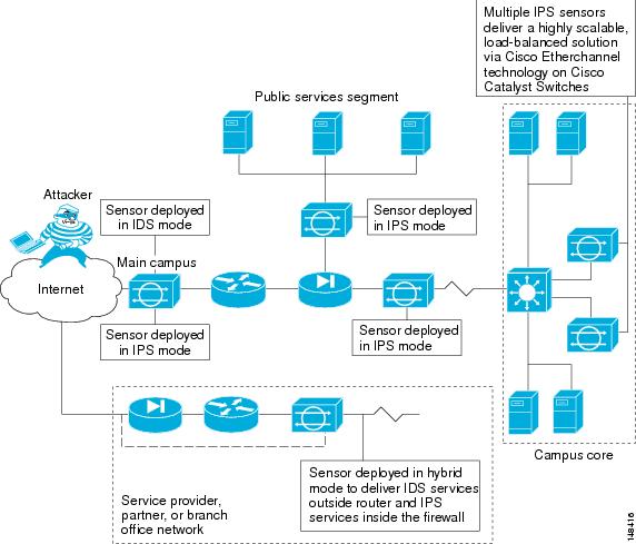
The command and control interface is always Ethernet. This interface has an assigned IP address, which allows it to communicate with the manager workstation or network devices (Cisco switches, routers, and firewalls). Because this interface is visible on the network, you should use encryption to maintain data privacy. SSH is used to protect the CLI and TLS/SSL is used to protect the manager workstation. SSH and TLS/SSL are enabled by default on the manager workstations.
When responding to attacks, the sensor can do the following:
•![]() Insert TCP resets via the sensing interface.
Insert TCP resets via the sensing interface.

Note ![]() You should select the TCP reset action only on signatures associated with a TCP-based service. If selected as an action on non-TCP-based services, no action is taken. Additionally, TCP resets are not guaranteed to tear down an offending session because of limitations in the TCP protocol.
You should select the TCP reset action only on signatures associated with a TCP-based service. If selected as an action on non-TCP-based services, no action is taken. Additionally, TCP resets are not guaranteed to tear down an offending session because of limitations in the TCP protocol.
•![]() Make ACL changes on switches, routers, and firewalls that the sensor manages.
Make ACL changes on switches, routers, and firewalls that the sensor manages.
Note ![]() ACLs may block only future traffic, not current traffic.
ACLs may block only future traffic, not current traffic.
•![]() Generate IP session logs, session replay, and trigger packets display.
Generate IP session logs, session replay, and trigger packets display.
IP session logs are used to gather information about unauthorized use. IP log files are written when events occur that you have configured the appliance to look for.
•![]() Implement multiple packet drop actions to stop worms and viruses.
Implement multiple packet drop actions to stop worms and viruses.
Your Network Topology
Before you deploy and configure your sensors, you should understand the following about your network:
•![]() The size and complexity of your network.
The size and complexity of your network.
•![]() Connections between your network and other networks (and the Internet).
Connections between your network and other networks (and the Internet).
•![]() The amount and type of network traffic on your network.
The amount and type of network traffic on your network.
This knowledge will help you determine how many sensors are required, the hardware configuration for each sensor (for example, the size and type of network interface cards), and how many managers are needed.
Correctly Deploying the Sensor
You should always position the IPS sensor behind a perimeter-filtering device, such as a firewall or adaptive security appliance. The perimeter device filters traffic to match your security policy thus allowing acceptable traffic in to your network. Correct placement significantly reduces the number of alerts, which increases the amount of actionable data you can use to investigate security violations. If you position the IPS sensor on the edge of your network in front of a firewall, your sensor will produce alerts on every single scan and attempted attack even if they have no significance to your network implementation. You will receive hundreds, thousands, or even millions of alerts (in a large enterprise environment) that are not really critical or actionable in your environment. Analyzing this type of data is time consuming and costly.
Tuning the IPS
Tuning the IPS ensures that the alerts you see reflect true actionable information. Without tuning the IPS, it is difficult to do security research or forensics on your network because you will have thousands of benign events, also known as false positives. False positives are a by-product of all IPS devices, but they occur much less frequently in Cisco IPS devices since Cisco IPS devices are stateful, normalized, and use vulnerability signatures for attack evaluation. Cisco IPS devices also provide risk rating, which identifies high risk events, and policy-based management, which lets you deploy rules to enforce IPS signature actions based on risk rating.
Follow these tips when tuning your IPS sensors:
•![]() Place your sensor on your network behind a perimeter-filtering device. Proper sensor placement can reduce the number of alerts you need to examine by several thousands a day.
Place your sensor on your network behind a perimeter-filtering device. Proper sensor placement can reduce the number of alerts you need to examine by several thousands a day.
•![]() Deploy the sensor with the default signatures in place.
Deploy the sensor with the default signatures in place.
The default signature set provides you with a very high security protection posture. The Cisco signature team has spent many hours on testing the defaults to give your sensor the highest protection. If you think that you have lost these defaults, you can restore them.
•![]() Make sure that the event action override is set to drop packets with a risk rating greater than 90. This is the default and ensures that high risk alerts are stopped immediately.
Make sure that the event action override is set to drop packets with a risk rating greater than 90. This is the default and ensures that high risk alerts are stopped immediately.
•![]() Filter out known false positives caused by specialized software, such as vulnerability scanner and load balancers by one of the following methods:
Filter out known false positives caused by specialized software, such as vulnerability scanner and load balancers by one of the following methods:
–![]() You can configure the sensor to ignore the alerts from the IP addresses of the scanner and load balancer.
You can configure the sensor to ignore the alerts from the IP addresses of the scanner and load balancer.
–![]() You can configure the sensor to allow these alerts and then use the IME to filter out the false positives.
You can configure the sensor to allow these alerts and then use the IME to filter out the false positives.
•![]() Filter the Informational alerts.
Filter the Informational alerts.
These low priority events notifications could indicate that another device is doing reconnaissance on a device protected by the IPS. Research the source IP addresses from these Informational alerts to determine what the source is.
•![]() Analyze the remaining actionable alerts:
Analyze the remaining actionable alerts:
–![]() Research the alert.
Research the alert.
–![]() Fix the attack source.
Fix the attack source.
–![]() Fix the destination host.
Fix the destination host.
–![]() Modify the IPS policy to provide more information.
Modify the IPS policy to provide more information.
For More Information
•![]() For a detailed description of risk rating, refer to Calculating the Risk Rating.
For a detailed description of risk rating, refer to Calculating the Risk Rating.
•![]() For information on Cisco signatures, for the IDM and IME refer to Defining Signatures, and for the CLI refer to Defining Signatures.
For information on Cisco signatures, for the IDM and IME refer to Defining Signatures, and for the CLI refer to Defining Signatures.
•![]() For detailed information on event action overrides, for the IDM and IME refer to Configuring Event Action Overrides, and for the CLI, refer to Configuring Event Action Overrides.
For detailed information on event action overrides, for the IDM and IME refer to Configuring Event Action Overrides, and for the CLI, refer to Configuring Event Action Overrides.
Sensor Interfaces
This section describes the sensor interfaces, and contains the following topics:
•![]() Understanding Sensor Interfaces
Understanding Sensor Interfaces
•![]() Command and Control Interface
Command and Control Interface
Understanding Sensor Interfaces
The sensor interfaces are named according to the maximum speed and physical location of the interface. The physical location consists of a port number and a slot number. All interfaces that are built-in on the sensor motherboard are in slot 0, and the interface card expansion slots are numbered beginning with slot 1 for the bottom slot with the slot numbers increasing from bottom to top. Each physical interface can be divided in to VLAN group subinterfaces, each of which consists of a group of VLANs on that interface.
There are three interface roles:
•![]() Command and control
Command and control
•![]() Sensing
Sensing
•![]() Alternate TCP reset
Alternate TCP reset
There are restrictions on which roles you can assign to specific interfaces and some interfaces have multiple roles. You can configure any sensing interface to any other sensing interface as its TCP reset interface. The TCP reset interface can also serve as an IDS (promiscuous) sensing interface at the same time. The following restrictions apply:
•![]() The TCP reset interface that is assigned to a sensing interface has no effect in inline interface or inline VLAN pair mode, because TCP resets are always sent on the sensing interfaces in those modes.
The TCP reset interface that is assigned to a sensing interface has no effect in inline interface or inline VLAN pair mode, because TCP resets are always sent on the sensing interfaces in those modes.
•![]() There is only one sensing interface on the ASA IPS modules (ASA 5500-X IPS SSP and ASA 5585-X IPS SSP), so you cannot designate an alternate TCP reset interface.
There is only one sensing interface on the ASA IPS modules (ASA 5500-X IPS SSP and ASA 5585-X IPS SSP), so you cannot designate an alternate TCP reset interface.
•![]() On the IPS 4510 and IPS 4520, no interface-related configurations are allowed when the SensorApp is down.
On the IPS 4510 and IPS 4520, no interface-related configurations are allowed when the SensorApp is down.
Command and Control Interface
The command and control interface has an IP address and is used for configuring the sensor. It receives security and status events from the sensor and queries the sensor for statistics. The command and control interface is permanently enabled. It is permanently mapped to a specific physical interface, which depends on the specific model of sensor. You cannot use the command and control interface as either a sensing or alternate TCP reset interface.
Table 1-1 lists the command and control interfaces for each sensor.
|
|
|
|---|---|
ASA 5512-X IPS SSP |
Management 0/0 |
ASA 5515-X IPS SSP |
Management 0/0 |
ASA 5525-X IPS SSP |
Management 0/0 |
ASA 5545-X IPS SSP |
Management 0/0 |
ASA 5555-X IPS SSP |
Management 0/0 |
ASA 5585-X IPS SSP-10 |
Management 0/0 |
ASA 5585-X IPS SSP-20 |
Management 0/0 |
ASA 5585-X IPS SSP-40 |
Management 0/0 |
ASA 5585-X IPS SSP-60 |
Management 0/0 |
IPS 4345 |
Management 0/0 |
IPS 4360 |
Management 0/0 |
IPS 4510 |
Management 0/01 |
IPS 4520 |
Management 0/01 |
1 The 4500 series sensors have two management ports, Management 0/0 and Management 0/1, but Management 0/1 is reserved for future use. |
Sensing Interfaces
Sensing interfaces are used by the sensor to analyze traffic for security violations. A sensor has one or more sensing interfaces depending on the sensor. Sensing interfaces can operate individually in promiscuous mode or you can pair them to create inline interfaces.
Note ![]() On appliances, all sensing interfaces are disabled by default. You must enable them to use them. On modules, the sensing interfaces are permanently enabled.
On appliances, all sensing interfaces are disabled by default. You must enable them to use them. On modules, the sensing interfaces are permanently enabled.
Some appliances support optional interface cards that add sensing interfaces to the sensor. You must insert or remove these optional cards while the sensor is powered off. The sensor detects the addition or removal of a supported interface card. If you remove an optional interface card, some of the interface configuration is deleted, such as the speed, duplex, description string, enabled/disabled state of the interface, and any inline interface pairings. These settings are restored to their default settings when the card is reinstalled. However, the assignment of promiscuous and inline interfaces to the Analysis Engine is not deleted from the Analysis Engine configuration, but is ignored until those cards are reinserted and you create the inline interface pairs again.
Interface Support
Table 1-2 describes the interface support for appliances and modules running Cisco IPS.
|
|
|
Inline VLAN Pairs (Sensing Ports) |
|
|
|---|---|---|---|---|
ASA 5512-X IPS SSP |
— |
PortChannel 0/0 by security context instead of VLAN pair or inline interface pair |
PortChannel 0/0 by security context instead of VLAN pair or inline interface pair |
Management 0/0 |
ASA 5515-X IPS SSP |
— |
PortChannel 0/0 by security context instead of VLAN pair or inline interface pair |
PortChannel 0/0 by security context instead of VLAN pair or inline interface pair |
Management 0/0 |
ASA 5525-X IPS SSP |
— |
PortChannel 0/0 by security context instead of VLAN pair or inline interface pair |
PortChannel 0/0 by security context instead of VLAN pair or inline interface pair |
Management 0/0 |
ASA 5545-X IPS SSP |
— |
PortChannel 0/0 by security context instead of VLAN pair or inline interface pair |
PortChannel 0/0 by security context instead of VLAN pair or inline interface pair |
Management 0/0 |
ASA 5555-X IPS SSP |
— |
PortChannel 0/0 by security context instead of VLAN pair or inline interface pair |
PortChannel 0/0 by security context instead of VLAN pair or inline interface pair |
Management 0/0 |
ASA 5585-X IPS SSP-10 |
— |
PortChannel 0/0 by security context instead of VLAN pair or inline interface pair |
PortChannel 0/0 by security context instead of VLAN pair or inline interface pair |
Management 0/0 |
ASA 5585-X IPS SSP-20 |
— |
PortChannel 0/0 by security context instead of VLAN pair or inline interface pair |
PortChannel 0/0 by security context instead of VLAN pair or inline interface pair |
Management 0/0 |
ASA 5585-X IPS SSP-40 |
— |
PortChannel 0/0 by security context instead of VLAN pair or inline interface pair |
PortChannel 0/0 by security context instead of VLAN pair or inline interface pair |
Management 0/0 |
ASA 5585-X IPS SSP-60 |
— |
PortChannel 0/0 by security context instead of VLAN pair or inline interface pair |
PortChannel 0/0 by security context instead of VLAN pair or inline interface pair |
Management 0/0 |
IPS 4345 |
— |
GigabitEthernet 0/0 GigabitEthernet 0/1 GigabitEthernet 0/2 GigabitEthernet 0/3 GigabitEthernet 0/4 GigabitEthernet 0/5 Gigabitethernet 0/6 GigabitEthernet 0/7 |
All sensing ports can be paired together |
Management 0/0 |
IPS 4360 |
— |
GigabitEthernet 0/0 GigabitEthernet 0/1 GigabitEthernet 0/2 GigabitEthernet 0/3 GigabitEthernet 0/4 GigabitEthernet 0/5 GigabitEthernet 0/6 GigabitEthernet 0/7 |
All sensing ports can be paired together |
Management 0/0 |
IPS 4510 |
— |
GigabitEthernet 0/0 GigabitEthernet 0/1 GigabitEthernet 0/2 GigabitEthernet 0/3 GigabitEthernet 0/4 GigabitEthernet 0/5 TenGigabitEthernet 0/6 TenGigabitEthernet 0/7 TenGigabitEthernet 0/8 TenGigabitEthernet 0/9 |
All sensing ports can be paired together |
Management 0/0 |
IPS 4520 |
—TX |
GigabitEthernet 0/0 GigabitEthernet 0/1 GigabitEthernet 0/2 GigabitEthernet 0/3 GigabitEthernet 0/4 GigabitEthernet 0/5 TenGigabitEthernet 0/6 TenGigabitEthernet 0/7 TenGigabitEthernet 0/8 TenGigabitEthernet 0/9 |
All sensing ports can be paired together |
Management 0/0 |
1 Does not currently support hardware bypass. 2 Reserved for future use. |
TCP Reset Interfaces
This section explains the TCP reset interfaces and when to use them. It contains the following topics:
•![]() Understanding Alternate TCP Reset Interfaces
Understanding Alternate TCP Reset Interfaces
•![]() Designating the Alternate TCP Reset Interface
Designating the Alternate TCP Reset Interface
Understanding Alternate TCP Reset Interfaces
Note ![]() The alternate TCP reset interface setting is ignored in inline interface or inline VLAN pair mode, because resets are sent inline in these modes.
The alternate TCP reset interface setting is ignored in inline interface or inline VLAN pair mode, because resets are sent inline in these modes.
You can configure sensors to send TCP reset packets to try to reset a network connection between an attacker host and its intended target host. In some installations when the interface is operating in promiscuous mode, the sensor may not be able to send the TCP reset packets over the same sensing interface on which the attack was detected. In such cases, you can associate the sensing interface with an alternate TCP reset interface and any TCP resets that would otherwise be sent on the sensing interface when it is operating in promiscuous mode are instead sent out on the associated alternate TCP reset interface.
If a sensing interface is associated with an alternate TCP reset interface, that association applies when the sensor is configured for promiscuous mode but is ignored when the sensing interface is configured for inline mode. any sensing interface can serve as the alternate TCP reset interface for another sensing interface.
Note ![]() There is only one sensing interface on the ASA IPS modules (ASA 5500-X IPS SSP and ASA 5585-X IPS SSP), so you cannot designate an alternate TCP reset interface.
There is only one sensing interface on the ASA IPS modules (ASA 5500-X IPS SSP and ASA 5585-X IPS SSP), so you cannot designate an alternate TCP reset interface.
Table 1-3 lists the alternate TCP reset interfaces.
Designating the Alternate TCP Reset Interface
Note ![]() There is only one sensing interface on the ASA IPS modules (ASA 5500-X IPS SSP and ASA 5585-X IPS SSP), so you cannot designate an alternate TCP reset interface.
There is only one sensing interface on the ASA IPS modules (ASA 5500-X IPS SSP and ASA 5585-X IPS SSP), so you cannot designate an alternate TCP reset interface.
You need to designate an alternate TCP reset interface in the following situations:
•![]() When a switch is being monitored with either SPAN or VACL capture and the switch does not accept incoming packets on the SPAN or VACL capture port.
When a switch is being monitored with either SPAN or VACL capture and the switch does not accept incoming packets on the SPAN or VACL capture port.
•![]() When a switch is being monitored with either SPAN or VACL capture for multiple VLANs, and the switch does not accept incoming packets with 802.1q headers. The TCP resets need 802.1q headers to tell which VLAN the resets should be sent on.
When a switch is being monitored with either SPAN or VACL capture for multiple VLANs, and the switch does not accept incoming packets with 802.1q headers. The TCP resets need 802.1q headers to tell which VLAN the resets should be sent on.
•![]() When a network tap is used for monitoring a connection. Taps do not permit incoming traffic from the sensor.
When a network tap is used for monitoring a connection. Taps do not permit incoming traffic from the sensor.

Interface Restrictions
The following restrictions apply to configuring interfaces on the sensor:
•![]() Physical Interfaces
Physical Interfaces
–![]() On the ASA IPS modules (ASA 5500-X IPS SSP and ASA 5585-X IPS SSP) all backplane interfaces have fixed speed, duplex, and state settings. These settings are protected in the default configuration on all backplane interfaces.
On the ASA IPS modules (ASA 5500-X IPS SSP and ASA 5585-X IPS SSP) all backplane interfaces have fixed speed, duplex, and state settings. These settings are protected in the default configuration on all backplane interfaces.
–![]() For nonbackplane FastEthernet interfaces the valid speed settings are 10 Mbps, 100 Mbps, and auto. Valid duplex settings are full, half, and auto.
For nonbackplane FastEthernet interfaces the valid speed settings are 10 Mbps, 100 Mbps, and auto. Valid duplex settings are full, half, and auto.
–![]() For Gigabit copper interfaces (1000-TX on the IPS 4345, IPS 4360, IPS 4510, and IPS 4520), valid speed settings are 10 Mbps, 100 Mbps, 1000 Mbps, and auto. Valid duplex settings are full, half, and auto.
For Gigabit copper interfaces (1000-TX on the IPS 4345, IPS 4360, IPS 4510, and IPS 4520), valid speed settings are 10 Mbps, 100 Mbps, 1000 Mbps, and auto. Valid duplex settings are full, half, and auto.
–![]() For Gigabit (copper or fiber) interfaces, if the speed is configured for 1000 Mbps, the only valid duplex setting is auto.
For Gigabit (copper or fiber) interfaces, if the speed is configured for 1000 Mbps, the only valid duplex setting is auto.
–![]() The command and control interface cannot also serve as a sensing interface.
The command and control interface cannot also serve as a sensing interface.
•![]() Inline Interface Pairs
Inline Interface Pairs
–![]() Inline interface pairs can contain any combination of sensing interfaces regardless of the physical interface type (copper versus fiber), speed, or duplex settings of the interface. However, pairing interfaces of different media type, speeds, and duplex settings may not be fully tested or supported.
Inline interface pairs can contain any combination of sensing interfaces regardless of the physical interface type (copper versus fiber), speed, or duplex settings of the interface. However, pairing interfaces of different media type, speeds, and duplex settings may not be fully tested or supported.
–![]() The command and control interface cannot be a member of an inline interface pair.
The command and control interface cannot be a member of an inline interface pair.
–![]() You cannot pair a physical interface with itself in an inline interface pair.
You cannot pair a physical interface with itself in an inline interface pair.
–![]() A physical interface can be a member of only one inline interface pair.
A physical interface can be a member of only one inline interface pair.
–![]() You can only configure bypass mode and create inline interface pairs on sensor platforms that support inline mode.
You can only configure bypass mode and create inline interface pairs on sensor platforms that support inline mode.
–![]() A physical interface cannot be a member of an inline interface pair unless the subinterface mode of the physical interface is none.
A physical interface cannot be a member of an inline interface pair unless the subinterface mode of the physical interface is none.
–![]() You can configure the ASA IPS modules (ASA 5500-X IPS SSP and ASA 5585-X IPS SSP) to operate inline even though they have only one sensing interface.
You can configure the ASA IPS modules (ASA 5500-X IPS SSP and ASA 5585-X IPS SSP) to operate inline even though they have only one sensing interface.
•![]() Inline VLAN Pairs
Inline VLAN Pairs
–![]() You cannot pair a VLAN with itself.
You cannot pair a VLAN with itself.
–![]() You cannot use the default VLAN as one of the paired VLANs in an inline VLAN pair.
You cannot use the default VLAN as one of the paired VLANs in an inline VLAN pair.
–![]() For a given sensing interface, a VLAN can be a member of only one inline VLAN pair. However, a given VLAN can be a member of an inline VLAN pair on more than one sensing interface.
For a given sensing interface, a VLAN can be a member of only one inline VLAN pair. However, a given VLAN can be a member of an inline VLAN pair on more than one sensing interface.
–![]() The order in which you specify the VLANs in an inline VLAN pair is not significant.
The order in which you specify the VLANs in an inline VLAN pair is not significant.
–![]() A sensing interface in Inline VLAN Pair mode can have from 1 to 255 inline VLAN pairs.
A sensing interface in Inline VLAN Pair mode can have from 1 to 255 inline VLAN pairs.
–![]() The ASA IPS modules (ASA 5500-X IPS SSP and ASA 5585-X IPS SSP) do not support inline VLAN pairs.
The ASA IPS modules (ASA 5500-X IPS SSP and ASA 5585-X IPS SSP) do not support inline VLAN pairs.
–![]() For the IPS 4510 and IPS 4520, the maximum number of inline VLAN pairs you can create systemwide is 150. On all other platforms, the limit is 255 per interface.
For the IPS 4510 and IPS 4520, the maximum number of inline VLAN pairs you can create systemwide is 150. On all other platforms, the limit is 255 per interface.
•![]() Alternate TCP Reset Interface
Alternate TCP Reset Interface
–![]() You can only assign the alternate TCP reset interface to a sensing interface. You cannot configure the command and control interface as an alternate TCP reset interface. The alternate TCP reset interface option is set to none as the default and is protected for all interfaces except the sensing interfaces.
You can only assign the alternate TCP reset interface to a sensing interface. You cannot configure the command and control interface as an alternate TCP reset interface. The alternate TCP reset interface option is set to none as the default and is protected for all interfaces except the sensing interfaces.
–![]() You can assign the same physical interface as an alternate TCP reset interface for multiple sensing interfaces.
You can assign the same physical interface as an alternate TCP reset interface for multiple sensing interfaces.
–![]() A physical interface can serve as both a sensing interface and an alternate TCP reset interface.
A physical interface can serve as both a sensing interface and an alternate TCP reset interface.
–![]() The command and control interface cannot serve as the alternate TCP reset interface for a sensing interface.
The command and control interface cannot serve as the alternate TCP reset interface for a sensing interface.
–![]() A sensing interface cannot serve as its own alternate TCP reset interface.
A sensing interface cannot serve as its own alternate TCP reset interface.
–![]() You can only configure interfaces that are capable of TCP resets as alternate TCP reset interfaces.
You can only configure interfaces that are capable of TCP resets as alternate TCP reset interfaces.
–![]() There is only one sensing interface on the ASA IPS modules (ASA 5500-X IPS SSP and ASA 5585-X IPS SSP), so you cannot designate an alternate TCP reset interface.
There is only one sensing interface on the ASA IPS modules (ASA 5500-X IPS SSP and ASA 5585-X IPS SSP), so you cannot designate an alternate TCP reset interface.
•![]() VLAN Groups
VLAN Groups
–![]() You can configure any single interface for promiscuous, inline interface pair, or inline VLAN pair mode, but no combination of these modes is allowed.
You can configure any single interface for promiscuous, inline interface pair, or inline VLAN pair mode, but no combination of these modes is allowed.
–![]() You cannot add a VLAN to more than one group on each interface.
You cannot add a VLAN to more than one group on each interface.
–![]() You cannot add a VLAN group to multiple virtual sensors.
You cannot add a VLAN group to multiple virtual sensors.
–![]() An interface can have no more than 255 user-defined VLAN groups.
An interface can have no more than 255 user-defined VLAN groups.
–![]() When you pair a physical interface, you cannot subdivide it; you can subdivide the pair.
When you pair a physical interface, you cannot subdivide it; you can subdivide the pair.
–![]() You can use a VLAN on multiple interfaces; however, you receive a warning for this configuration.
You can use a VLAN on multiple interfaces; however, you receive a warning for this configuration.
–![]() You can assign a virtual sensor to any combination of one or more physical interfaces and inline VLAN pairs, subdivided or not.
You can assign a virtual sensor to any combination of one or more physical interfaces and inline VLAN pairs, subdivided or not.
–![]() You can subdivide both physical and logical interfaces into VLAN groups.
You can subdivide both physical and logical interfaces into VLAN groups.
–![]() The CLI, IDM, and IME prompt you to remove any dangling references. You can leave the dangling references and continue editing the configuration.
The CLI, IDM, and IME prompt you to remove any dangling references. You can leave the dangling references and continue editing the configuration.
–![]() The CLI, IDM, and IME do not allow configuration changes in Analysis Engine that conflict with the interface configuration.
The CLI, IDM, and IME do not allow configuration changes in Analysis Engine that conflict with the interface configuration.
–![]() The CLI allows configuration changes in the interface configuration that cause conflicts in the Analysis Engine configuration. The IDM and IME do not allow changes in the interface configuration that cause conflicts in the Analysis Engine configuration.
The CLI allows configuration changes in the interface configuration that cause conflicts in the Analysis Engine configuration. The IDM and IME do not allow changes in the interface configuration that cause conflicts in the Analysis Engine configuration.
–![]() The ASA IPS modules (ASA 5500-X IPS SSP and ASA 5585-X IPS SSP) do not support VLAN groups mode.
The ASA IPS modules (ASA 5500-X IPS SSP and ASA 5585-X IPS SSP) do not support VLAN groups mode.
Interface Modes
The following section describes the interface modes, and contains the following topics:
•![]() IPv6, Switches, and Lack of VACL Capture
IPv6, Switches, and Lack of VACL Capture
Promiscuous Mode
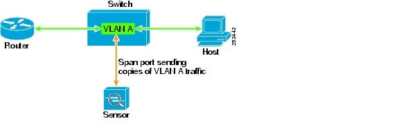
In promiscuous mode, packets do not flow through the sensor. The sensor analyzes a copy of the monitored traffic rather than the actual forwarded packet. The advantage of operating in promiscuous mode is that the sensor does not affect the packet flow with the forwarded traffic. The disadvantage of operating in promiscuous mode, however, is the sensor cannot stop malicious traffic from reaching its intended target for certain types of attacks, such as atomic attacks (single-packet attacks). The response actions implemented by promiscuous sensor devices are post-event responses and often require assistance from other networking devices, for example, routers and firewalls, to respond to an attack. While such response actions can prevent some classes of attacks, in atomic attacks the single packet has the chance of reaching the target system before the promiscuous-based sensor can apply an ACL modification on a managed device (such as a firewall, switch, or router).
By default, all sensing interfaces are in promiscuous mode. To change an interface from inline interface mode to promiscuous mode, delete any inline interface that contains that interface and delete any inline VLAN pair subinterfaces of that interface from the interface configuration.
Figure 1-2 illustrates promiscuous mode:
Figure 1-2 Promiscuous Mode
IPv6, Switches, and Lack of VACL Capture
VACLs on Catalyst switches do not have IPv6 support. The most common method for copying traffic to a sensor configured in promiscuous mode is to use VACL capture. If you want to have IPv6 support, you can use SPAN ports.
However, you can only configure up to two monitor sessions on a switch unless you use the following configuration:
•![]() Monitor session
Monitor session
•![]() Multiple trunks to one or more sensors
Multiple trunks to one or more sensors
•![]() Restrict per trunk port which VLANs are allowed to perform monitoring of many VLANs to more than two different sensors or virtual sensors within one IPS
Restrict per trunk port which VLANs are allowed to perform monitoring of many VLANs to more than two different sensors or virtual sensors within one IPS
The following configuration uses one SPAN session to send all of the traffic on any of the specified VLANs to all of the specified ports. Each port configuration only allows a particular VLAN or VLANs to pass. Thus you can send data from different VLANs to different sensors or virtual sensors all with one SPAN configuration line:
clear trunk 4/1-4 1-4094
set trunk 4/1 on dot1q 930
set trunk 4/2 on dot1q 932
set trunk 4/3 on dot1q 960
set trunk 4/4 on dot1q 962
set span 930, 932, 960, 962 4/1-4 both
Note ![]() The SPAN/Monitor configuration is valuable when you want to assign different IPS policies per VLAN or when you have more bandwidth to monitor than one interface can handle.
The SPAN/Monitor configuration is valuable when you want to assign different IPS policies per VLAN or when you have more bandwidth to monitor than one interface can handle.
For More Information
For more information on promiscuous mode, see Promiscuous Mode.
Inline Interface Pair Mode
Operating in inline interface pair mode puts the IPS directly into the traffic flow and affects packet-forwarding rates making them slower by adding latency. This allows the sensor to stop attacks by dropping malicious traffic before it reaches the intended target, thus providing a protective service. Not only is the inline device processing information on Layers 3 and 4, but it is also analyzing the contents and payload of the packets for more sophisticated embedded attacks (Layers 3 to 7). This deeper analysis lets the system identify and stop and/or block attacks that would normally pass through a traditional firewall device.
In inline interface pair mode, a packet comes in through the first interface of the pair on the sensor and out the second interface of the pair. The packet is sent to the second interface of the pair unless that packet is being denied or modified by a signature.
Note ![]() You can configure the ASA IPS modules (ASA 5500-X IPS SSP and ASA 5585-X IPS SSP) to operate inline even though they have only one sensing interface.
You can configure the ASA IPS modules (ASA 5500-X IPS SSP and ASA 5585-X IPS SSP) to operate inline even though they have only one sensing interface.
Note ![]() If the paired interfaces are connected to the same switch, you should configure them on the switch as access ports with different access VLANs for the two ports. Otherwise, traffic does not flow through the inline interface.
If the paired interfaces are connected to the same switch, you should configure them on the switch as access ports with different access VLANs for the two ports. Otherwise, traffic does not flow through the inline interface.
Figure 1-3 illustrates inline interface pair mode:
Figure 1-3 Inline Interface Pair Mode

Inline VLAN Pair Mode
Note ![]() The ASA IPS modules (ASA 5500-X IPS SSP and ASA 5585-X IPS SSP) do not support inline VLAN pairs.
The ASA IPS modules (ASA 5500-X IPS SSP and ASA 5585-X IPS SSP) do not support inline VLAN pairs.
Note ![]() For the IPS 4510 and IPS 4520, the maximum number of inline VLAN pairs you can create systemwide is 150. On all other platforms, the limit is 255 per interface.
For the IPS 4510 and IPS 4520, the maximum number of inline VLAN pairs you can create systemwide is 150. On all other platforms, the limit is 255 per interface.
You can associate VLANs in pairs on a physical interface. This is known as inline VLAN pair mode. Packets received on one of the paired VLANs are analyzed and then forwarded to the other VLAN in the pair.
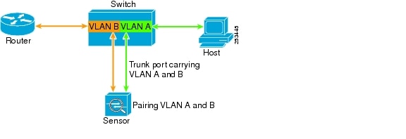
Inline VLAN pair mode is an active sensing mode where a sensing interface acts as an 802.1q trunk port, and the sensor performs VLAN bridging between pairs of VLANs on the trunk. The sensor inspects the traffic it receives on each VLAN in each pair, and can either forward the packets on the other VLAN in the pair, or drop the packet if an intrusion attempt is detected. You can configure an IPS sensor to simultaneously bridge up to 255 VLAN pairs on each sensing interface. The sensor replaces the VLAN ID field in the 802.1q header of each received packet with the ID of the egress VLAN on which the sensor forwards the packet. The sensor drops all packets received on any VLANs that are not assigned to inline VLAN pairs.
Note ![]() You cannot use the default VLAN as one of the paired VLANs in an inline VLAN pair.
You cannot use the default VLAN as one of the paired VLANs in an inline VLAN pair.
Figure 1-4 illustrates inline VLAN pair mode:
Figure 1-4 Inline VLAN Pair Mode
VLAN Group Mode
Note ![]() The ASA IPS modules (ASA 5500-X IPS SSP and ASA 5585-X IPS SSP) do not support VLAN groups mode.
The ASA IPS modules (ASA 5500-X IPS SSP and ASA 5585-X IPS SSP) do not support VLAN groups mode.
You can divide each physical interface or inline interface into VLAN group subinterfaces, each of which consists of a group of VLANs on that interface. Analysis Engine supports multiple virtual sensors, each of which can monitor one or more of these interfaces. This lets you apply multiple policies to the same sensor. The advantage is that now you can use a sensor with only a few interfaces as if it had many interfaces.
Note ![]() You cannot divide physical interfaces that are in inline VLAN pairs into VLAN groups.
You cannot divide physical interfaces that are in inline VLAN pairs into VLAN groups.
VLAN group subinterfaces associate a set of VLANs with a physical or inline interface. No VLAN can be a member of more than one VLAN group subinterface. Each VLAN group subinterface is identified by a number between 1 and 255. Subinterface 0 is a reserved subinterface number used to represent the entire unvirtualized physical or logical interface. You cannot create, delete, or modify subinterface 0 and no statistics are reported for it.
An unassigned VLAN group is maintained that contains all VLANs that are not specifically assigned to another VLAN group. You cannot directly specify the VLANs that are in the unassigned group. When a VLAN is added to or deleted from another VLAN group subinterface, the unassigned group is updated.
Packets in the native VLAN of an 802.1q trunk do not normally have 802.1q encapsulation headers to identify the VLAN number to which the packets belong. A default VLAN variable is associated with each physical interface and you should set this variable to the VLAN number of the native VLAN or to 0. The value 0 indicates that the native VLAN is either unknown or you do not care if it is specified. If the default VLAN setting is 0, the following occurs:
•![]() Any alerts triggered by packets without 802.1q encapsulation have a VLAN value of 0 reported in the alert.
Any alerts triggered by packets without 802.1q encapsulation have a VLAN value of 0 reported in the alert.
•![]() Non-802.1q encapsulated traffic is associated with the unassigned VLAN group and it is not possible to assign the native VLAN to any other VLAN group.
Non-802.1q encapsulated traffic is associated with the unassigned VLAN group and it is not possible to assign the native VLAN to any other VLAN group.
Note ![]() You can configure a port on a switch as either an access port or a trunk port. On an access port, all traffic is in a single VLAN is called the access VLAN. On a trunk port, multiple VLANs can be carried over the port, and each packet has a special header attached called the 802.1q header that contains the VLAN ID. This header is commonly referred as the VLAN tag. However, a trunk port has a special VLAN called the native VLAN. Packets in the native VLAN do not have the 802.1q headers attached.
You can configure a port on a switch as either an access port or a trunk port. On an access port, all traffic is in a single VLAN is called the access VLAN. On a trunk port, multiple VLANs can be carried over the port, and each packet has a special header attached called the 802.1q header that contains the VLAN ID. This header is commonly referred as the VLAN tag. However, a trunk port has a special VLAN called the native VLAN. Packets in the native VLAN do not have the 802.1q headers attached.
Deploying VLAN Groups
Because a VLAN group of an inline pair does not translate the VLAN ID, an inline paired interface must exist between two switches to use VLAN groups on a logical interface. For an appliance, you can connect the two pairs to the same switch, make them access ports, and then set the access VLANs for the two ports differently. In this configuration, the sensor connects between two VLANs, because each of the two ports is in access mode and carries only one VLAN. In this case the two ports must be in different VLANs, and the sensor bridges the two VLANs, monitoring any traffic that flows between the two VLANs.
You can also connect appliances between two switches. There are two variations. In the first variation, the two ports are configured as access ports, so they carry a single VLAN. In this way, the sensor bridges a single VLAN between the two switches.
In the second variation, the two ports are configured as trunk ports, so they can carry multiple VLANs. In this configuration, the sensor bridges multiple VLANs between the two switches. Because multiple VLANs are carried over the inline interface pair, the VLANs can be divided into groups and each group can be assigned to a virtual sensor.
Supported Sensors
For a list of the specific IPS filenames and the IPS versions that each sensor supports, refer to the Release Notes for your IPS version found at this URL:
http://www.cisco.com/en/US/products/hw/vpndevc/ps4077/prod_release_notes_list.html
Table 1-4 lists the sensors (IPS appliances and modules) that are supported by Cisco IPS.
For More Information
For instructions on how to obtain the most recent Cisco IPS software, see Obtaining Cisco IPS Software.
IPS Appliances
This section describes the Cisco appliance, and contains the following topics:
•![]() Introducing the IPS Appliance
Introducing the IPS Appliance
•![]() Connecting an Appliance to a Terminal Server
Connecting an Appliance to a Terminal Server
Introducing the IPS Appliance
Note ![]() The currently supported Cisco IPS appliances are the IPS 4345, IPS 4360, IPS 4510, and IPS 4520.
The currently supported Cisco IPS appliances are the IPS 4345, IPS 4360, IPS 4510, and IPS 4520.
The IPS appliance is a high-performance, plug-and-play device. The appliance is a component of the IPS, a network-based, real-time intrusion prevention system. You can use the IPS CLI, IDM, IME, ASDM, or CSM to configure the appliance. For a list of IPS documents and how to access them, refer to Documentation Roadmap for Cisco Intrusion Prevention System 7.2.
You can configure the appliance to respond to recognized signatures as it captures and analyzes network traffic. These responses include logging the event, forwarding the event to the manager, performing a TCP reset, generating an IP log, capturing the alert trigger packet, and reconfiguring a router. The appliance offers significant protection to your network by helping to detect, classify, and stop threats including worms, spyware and adware, network viruses, and application abuse.
After being installed at key points in the network, the appliance monitors and performs real-time analysis of network traffic by looking for anomalies and misuse based on an extensive, embedded signature library. When the system detects unauthorized activity, appliances can terminate the specific connection, permanently block the attacking host, log the incident, and send an alert to the manager. Other legitimate connections continue to operate independently without interruption.
Appliances are optimized for specific data rates and are packaged in Ethernet, Fast Ethernet, and Gigabit Ethernet configurations. In switched environments, appliances must be connected to the SPAN port or VACL capture port of the switch.
The Cisco IPS appliances provide the following:
•![]() Protection of multiple network subnets through the use of up to eight interfaces
Protection of multiple network subnets through the use of up to eight interfaces
•![]() Simultaneous, dual operation in both promiscuous and inline modes
Simultaneous, dual operation in both promiscuous and inline modes
•![]() A wide array of performance options—from 80 Mbps to multiple gigabits
A wide array of performance options—from 80 Mbps to multiple gigabits
•![]() Embedded web-based management solutions packaged with the sensor
Embedded web-based management solutions packaged with the sensor
For More Information
•![]() For a list of supported appliances, see Supported Sensors.
For a list of supported appliances, see Supported Sensors.
•![]() For a description of the IPS 4345 and IPS 4360, see Chapter 3 "Installing the IPS 4345 and IPS 4360."
For a description of the IPS 4345 and IPS 4360, see Chapter 3 "Installing the IPS 4345 and IPS 4360."
•![]() For a description of the IPS 4510 and IPS 4520, see Chapter 4 "Installing the IPS 4510 and IPS 4520."
For a description of the IPS 4510 and IPS 4520, see Chapter 4 "Installing the IPS 4510 and IPS 4520."
•![]() For a description of the ASA 5585-X IPS SSP, see Chapter 5 "Installing and Removing the ASA 5585-X IPS SSP."
For a description of the ASA 5585-X IPS SSP, see Chapter 5 "Installing and Removing the ASA 5585-X IPS SSP."
Appliance Restrictions
The following restrictions apply to using and operating the appliance:
•![]() The appliance is not a general purpose workstation.
The appliance is not a general purpose workstation.
•![]() Cisco Systems prohibits using the appliance for anything other than operating Cisco IPS.
Cisco Systems prohibits using the appliance for anything other than operating Cisco IPS.
•![]() Cisco Systems prohibits modifying or installing any hardware or software in the appliance that is not part of the normal operation of the Cisco IPS.
Cisco Systems prohibits modifying or installing any hardware or software in the appliance that is not part of the normal operation of the Cisco IPS.
Connecting an Appliance to a Terminal Server
A terminal server is a router with multiple, low speed, asynchronous ports that are connected to other serial devices. You can use terminal servers to remotely manage network equipment, including appliances.
To set up a Cisco terminal server with RJ-45 or hydra cable assembly connections, follow these steps:
Step 1 ![]() Connect to a terminal server using one of the following methods:
Connect to a terminal server using one of the following methods:
•![]() For terminal servers with RJ-45 connections, connect a rollover cable from the console port on the appliance to a port on the terminal server.
For terminal servers with RJ-45 connections, connect a rollover cable from the console port on the appliance to a port on the terminal server.
•![]() For hydra cable assemblies, connect a straight-through patch cable from the console port on the appliance to a port on the terminal server.
For hydra cable assemblies, connect a straight-through patch cable from the console port on the appliance to a port on the terminal server.
Step 2 ![]() Configure the line and port on the terminal server. In enable mode, enter the following configuration, where # is the line number of the port to be configured.
Configure the line and port on the terminal server. In enable mode, enter the following configuration, where # is the line number of the port to be configured.
config t
line #
login
transport input all
stopbits 1
flowcontrol hardware
speed 9600
exit
exit
wr mem
Step 3 ![]() Be sure to properly close a terminal session to avoid unauthorized access to the appliance. If a terminal session is not stopped properly, that is, if it does not receive an exit(0) signal from the application that initiated the session, the terminal session can remain open. When terminal sessions are not stopped properly, authentication is not performed on the next session that is opened on the serial port.
Be sure to properly close a terminal session to avoid unauthorized access to the appliance. If a terminal session is not stopped properly, that is, if it does not receive an exit(0) signal from the application that initiated the session, the terminal session can remain open. When terminal sessions are not stopped properly, authentication is not performed on the next session that is opened on the serial port.
Time Sources and the Sensor
This section explains the importance of having a reliable time source for the sensors and how to correct the time if there is an error. It contains the following topics:
•![]() Synchronizing IPS Module System Clocks with the Parent Device System Clock
Synchronizing IPS Module System Clocks with the Parent Device System Clock
•![]() Verifying the Sensor is Synchronized with the NTP Server
Verifying the Sensor is Synchronized with the NTP Server
•![]() Correcting the Time on the Sensor
Correcting the Time on the Sensor
The Sensor and Time Sources
Note ![]() We recommend that you use an NTP server to regulate time on your sensor. You can use authenticated or unauthenticated NTP. For authenticated NTP, you must obtain the NTP server IP address, NTP server key ID, and the key value from the NTP server. You can set up NTP during initialization or you can configure NTP through the CLI, IDM, IME, or ASDM.
We recommend that you use an NTP server to regulate time on your sensor. You can use authenticated or unauthenticated NTP. For authenticated NTP, you must obtain the NTP server IP address, NTP server key ID, and the key value from the NTP server. You can set up NTP during initialization or you can configure NTP through the CLI, IDM, IME, or ASDM.
The sensor requires a reliable time source. All events (alerts) must have the correct UTC and local time stamp, otherwise, you cannot correctly analyze the logs after an attack. When you initialize the sensor, you set up the time zones and summertime settings. This section provides a summary of the various ways to set the time on sensors.
The IPS Standalone Appliances
•![]() Use the clock set command to set the time. This is the default.
Use the clock set command to set the time. This is the default.
•![]() Configure the appliance to get its time from an NTP time synchronization source.
Configure the appliance to get its time from an NTP time synchronization source.
Note ![]() The currently supported Cisco IPS appliances are the IPS 4345, IPS 4360, IPS 4510, and IPS 4520.
The currently supported Cisco IPS appliances are the IPS 4345, IPS 4360, IPS 4510, and IPS 4520.
The ASA IPS Modules
•![]() The ASA 5500-X IPS SSP and ASA 5585-X IPS SSP automatically synchronize their clocks with the clock in the adaptive security appliance in which they are installed. This is the default.
The ASA 5500-X IPS SSP and ASA 5585-X IPS SSP automatically synchronize their clocks with the clock in the adaptive security appliance in which they are installed. This is the default.
•![]() Configure them to get their time from an NTP time synchronization source, such as a Cisco router other than the parent router.
Configure them to get their time from an NTP time synchronization source, such as a Cisco router other than the parent router.
Synchronizing IPS Module System Clocks with the Parent Device System Clock
The IPS modules (ASA 5500-X IPS SSP and ASA 5585-X IPS SSP) synchronize their clocks to the parent chassis clock (switch, router, or adaptive security appliance) each time the IPS boots up and any time the parent chassis clock is set. The IPS clock and parent chassis clock tend to drift apart over time. The difference can be as much as several seconds per day. To avoid this problem, make sure that both the IPS clock and the parent clock are synchronized to an external NTP server. If only the IPS clock or only the parent chassis clock is synchronized to an NTP server, the time drift occurs.
Verifying the Sensor is Synchronized with the NTP Server
In the Cisco IPS, you cannot apply an incorrect NTP configuration, such as an invalid NTP key value or ID, to the sensor. If you try to apply an incorrect configuration, you receive an error message. To verify the NTP configuration, use the show statistics host command to gather sensor statistics. The NTP statistics section provides NTP statistics including feedback on sensor synchronization with the NTP server.
To verify the NTP configuration, follow these steps:
Step 1 ![]() Log in to the sensor.
Log in to the sensor.
Step 2 ![]() Generate the host statistics.
Generate the host statistics.
sensor# show statistics host
...
NTP Statistics
remote refid st t when poll reach delay offset jitter
11.22.33.44 CHU_AUDIO(1) 8 u 36 64 1 0.536 0.069 0.001
LOCAL(0) 73.78.73.84 5 l 35 64 1 0.000 0.000 0.001
ind assID status conf reach auth condition last_event cnt
1 10372 f014 yes yes ok reject reachable 1
2 10373 9014 yes yes none reject reachable 1
status = Not Synchronized
...
Step 3 ![]() Generate the hosts statistics again after a few minutes.
Generate the hosts statistics again after a few minutes.
sensor# show statistics host
...
NTP Statistics
remote refid st t when poll reach delay offset jitter
*11.22.33.44 CHU_AUDIO(1) 8 u 22 64 377 0.518 37.975 33.465
LOCAL(0) 73.78.73.84 5 l 22 64 377 0.000 0.000 0.001
ind assID status conf reach auth condition last_event cnt
1 10372 f624 yes yes ok sys.peer reachable 2
2 10373 9024 yes yes none reject reachable 2
status = Synchronized
Step 4 ![]() If the status continues to read
If the status continues to read Not Synchronized, check with the NTP server administrator to make sure the NTP server is configured correctly.
Correcting the Time on the Sensor
If you set the time incorrectly, your stored events will have the incorrect time because they are stamped with the time the event was created. The Event Store time stamp is always based on UTC time. If during the original sensor setup, you set the time incorrectly by specifying 8:00 p.m. rather than 8:00 a.m., when you do correct the error, the corrected time will be set backwards. New events might have times older than old events.
For example, if during the initial setup, you configure the sensor as central time with daylight saving time enabled and the local time is 8:04 p.m., the time is displayed as 20:04:37 CDT and has an offset from UTC of -5 hours (01:04:37 UTC, the next day). A week later at 9:00 a.m., you discover the error: the clock shows 21:00:23 CDT. You then change the time to 9:00 a.m. and now the clock shows 09:01:33 CDT. Because the offset from UTC has not changed, it requires that the UTC time now be 14:01:33 UTC, which creates the time stamp problem.
To ensure the integrity of the time stamp on the event records, you must clear the event archive of the older events by using the clear events command.
Note ![]() You cannot remove individual events.
You cannot remove individual events.
For More Information
For the procedure for clearing events, refer to Clearing Events from Event Store.
 Feedback