Cisco Intrusion Prevention System Appliance and Module Installation Guide for IPS 5.1
Bias-Free Language
The documentation set for this product strives to use bias-free language. For the purposes of this documentation set, bias-free is defined as language that does not imply discrimination based on age, disability, gender, racial identity, ethnic identity, sexual orientation, socioeconomic status, and intersectionality. Exceptions may be present in the documentation due to language that is hardcoded in the user interfaces of the product software, language used based on RFP documentation, or language that is used by a referenced third-party product. Learn more about how Cisco is using Inclusive Language.
- Updated:
- November 17, 2006
Chapter: Installing IDS-4210
Installing IDS-4210
This chapter describes IDS-4210 and how to install it and its accessories.

Note ![]() IDS-4215 replaced IDS-4210, which is no longer sold.
IDS-4215 replaced IDS-4210, which is no longer sold.
Note ![]() If you purchased an IDS-4210 before July 2003, you must upgrade the memory to 512 MB to install Cisco IPS 5.x. for more information, see Upgrading the Memory.
If you purchased an IDS-4210 before July 2003, you must upgrade the memory to 512 MB to install Cisco IPS 5.x. for more information, see Upgrading the Memory.
Note ![]() IDS-4210 does not support inline (IPS) mode.
IDS-4210 does not support inline (IPS) mode.

This chapter contains the following sections:
•![]() Front and Back Panel Features and Indicators
Front and Back Panel Features and Indicators
Front and Back Panel Features and Indicators
Figure 2-1 shows the front panel indicators on IDS-4210.
Figure 2-1 Front Panel Features
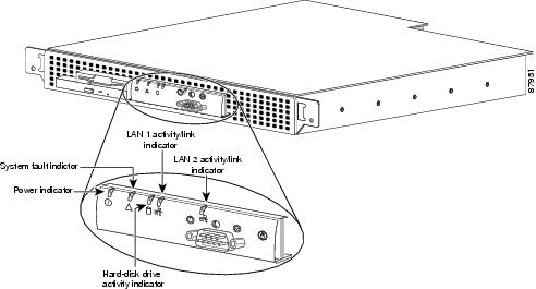
Table 2-1 describes the appearance and function of the front panel indicators.
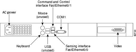
Figure 2-2 shows the back panel features on IDS-4210.
Figure 2-2 Back Panel Features
Upgrading the Memory
IDS-4210, IDS-4210-K9, and IDS-4210-NFR must have 512 MB of RAM to support Cisco IPS 5.1. If you are upgrading an existing IDS-4210, IDS-4210-K9, or IDS-4210-NFR to 5.1, you must insert one additional 256-MB DIMM (part number IDS-4210-MEM-U) to upgrade the memory to the required 512 MB minimum.
Note ![]() Do not install an unsupported DIMM. Doing so nullifies the warranty.
Do not install an unsupported DIMM. Doing so nullifies the warranty.
To upgrade the memory, follow these steps:
Step 1 ![]() Log in to the CLI.
Log in to the CLI.
Step 2 ![]() Prepare the appliance to be powered off:
Prepare the appliance to be powered off:
sensor# reset powerdown
Wait for the power down message before continuing with Step 3.
Note ![]() You can also power down the sensor from IDM or ASDM.
You can also power down the sensor from IDM or ASDM.
Step 3 ![]() Power off the appliance.
Power off the appliance.
Step 4 ![]() Remove the power cord and other cables from the appliance.
Remove the power cord and other cables from the appliance.
Step 5 ![]() Place the appliance in an ESD-controlled environment.
Place the appliance in an ESD-controlled environment.
For more information, see Working in an ESD Environment.
Step 6 ![]() Remove the chassis cover by unscrewing the screw on the front of the cover and sliding the cover straight back.
Remove the chassis cover by unscrewing the screw on the front of the cover and sliding the cover straight back.
Step 7 ![]() Locate the DIMM sockets and select the empty DIMM socket next to the existing DIMM.
Locate the DIMM sockets and select the empty DIMM socket next to the existing DIMM.
Note ![]() The existing DIMM is installed in socket 0. The angled position of the DIMM sockets make installing an additional DIMM in socket 1 difficult if a DIMM occupies socket 0. Therefore, you should first remove the existing DIMM from socket 0, place the new DIMM in socket 1, and then replace the existing DIMM in socket 0.
The existing DIMM is installed in socket 0. The angled position of the DIMM sockets make installing an additional DIMM in socket 1 difficult if a DIMM occupies socket 0. Therefore, you should first remove the existing DIMM from socket 0, place the new DIMM in socket 1, and then replace the existing DIMM in socket 0.
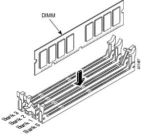
Step 8 ![]() Locate the ejector tabs on either side of the DIMM socket. Press down and out on tabs to open the slot in the socket.
Locate the ejector tabs on either side of the DIMM socket. Press down and out on tabs to open the slot in the socket.
Step 9 ![]() Install the new DIMM, by positioning the DIMM into the socket and pressing it into place.
Install the new DIMM, by positioning the DIMM into the socket and pressing it into place.
Note ![]() Do not force the DIMM into the socket. Alignment keys on the DIMM ensure that it only fits in the socket one way. If you need additional leverage, you can gently press down on the DIMM with your thumbs while pulling up on the ejector tabs.
Do not force the DIMM into the socket. Alignment keys on the DIMM ensure that it only fits in the socket one way. If you need additional leverage, you can gently press down on the DIMM with your thumbs while pulling up on the ejector tabs.
Step 10 ![]() Replace the chassis cover and reconnect the power.
Replace the chassis cover and reconnect the power.
Step 11 ![]() Power on the sensor and make sure the new memory total is correct.
Power on the sensor and make sure the new memory total is correct.
Note ![]() If the memory total does not reflect the added DIMMs, repeat Steps 1 through 4 to ensure the DIMMs are seated correctly in the socket.
If the memory total does not reflect the added DIMMs, repeat Steps 1 through 4 to ensure the DIMMs are seated correctly in the socket.
Installing IDS-4210
 |
Warning |
Note ![]() If you purchased an IDS-4210 before July 2003, you must upgrade the memory to 512 MB to install Cisco IPS 5.x. For more information, see Upgrading the Memory.
If you purchased an IDS-4210 before July 2003, you must upgrade the memory to 512 MB to install Cisco IPS 5.x. For more information, see Upgrading the Memory.
To install IDS-4210 on the network, follow these steps:
Step 1 ![]() Position IDS-4210 on the network.
Position IDS-4210 on the network.
Step 2 ![]() Attach the power cord to IDS-4210 and plug it in to a power source (a UPS is recommended).
Attach the power cord to IDS-4210 and plug it in to a power source (a UPS is recommended).
Note ![]() When you first plug an IDS-4210 into a power source, it powers on momentarily and then powers off leaving the NIC link lights lit. This is normal behavior. Press the power switch to boot the system into operation.
When you first plug an IDS-4210 into a power source, it powers on momentarily and then powers off leaving the NIC link lights lit. This is normal behavior. Press the power switch to boot the system into operation.
Step 3 ![]() Use the dual serial communication cable (PN 72-1847-01, included in the accessory kit) to attach a laptop to the COM1 port of IDS-4210 (see Table 2-2 for a list of the terminal settings), or connect a keyboard and monitor to IDS-4210.
Use the dual serial communication cable (PN 72-1847-01, included in the accessory kit) to attach a laptop to the COM1 port of IDS-4210 (see Table 2-2 for a list of the terminal settings), or connect a keyboard and monitor to IDS-4210.
|
|
|
|---|---|
Bits per second |
9600 |
Data bits |
8 |
Parity |
None |
Stop bits |
1 |
Flow control |
Hardware or RTS/CTS |
Note ![]() You can use a 180 rollover or straight-through patch cable to connect IDS-4210 to a port on a terminal server with RJ-45 or hydra cable assembly connections. Use a M.A.S.H adapter (part number 29-4077-02) to connect the appropriate cable to a port on the terminal server. For the instructions for setting up a terminal server, see Setting Up a Terminal Server.
You can use a 180 rollover or straight-through patch cable to connect IDS-4210 to a port on a terminal server with RJ-45 or hydra cable assembly connections. Use a M.A.S.H adapter (part number 29-4077-02) to connect the appropriate cable to a port on the terminal server. For the instructions for setting up a terminal server, see Setting Up a Terminal Server.
Step 4 ![]() Attach the network cables.
Attach the network cables.
IDS-4210 has the following interfaces:
•![]() FastEthernet0/0 is the sensing port.
FastEthernet0/0 is the sensing port.
•![]() FastEthernet0/1 is the command and control port.
FastEthernet0/1 is the command and control port.
Step 5 ![]() Upgrade the memory on IDS-4210.
Upgrade the memory on IDS-4210.
For the procedure, see Upgrading the Memory.
Step 6 ![]() Power on IDS-4210.
Power on IDS-4210.
Step 7 ![]() Initialize IDS-4210.
Initialize IDS-4210.
For the procedure, see Initializing the Sensor.
Step 8 ![]() Upgrade IDS-4210 to the latest Cisco IPS software.
Upgrade IDS-4210 to the latest Cisco IPS software.
For the procedure, see Obtaining Cisco IPS Software.
You are now ready to configure intrusion detection on the appliance.
For More Information
•![]() For the procedure for using HTTPS to log in to IDM, refer to Logging In to IDM.
For the procedure for using HTTPS to log in to IDM, refer to Logging In to IDM.
•![]() For the procedures for configuring intrusion prevention on your sensor, refer to the following documents:
For the procedures for configuring intrusion prevention on your sensor, refer to the following documents:
–![]() Installing and Using Cisco Intrusion Prevention System Device Manager 5.1
Installing and Using Cisco Intrusion Prevention System Device Manager 5.1
–![]() Configuring the Cisco Intrusion Prevention System Sensor Using the Command Line Interface 5.1
Configuring the Cisco Intrusion Prevention System Sensor Using the Command Line Interface 5.1
Installing the Accessories
You can install a bezel, and center or front mounting brackets for the IDS-4210.
This section contains the following topics:
•![]() Installing and Removing the Bezel
Installing and Removing the Bezel
•![]() Installing Center Mount Brackets
Installing Center Mount Brackets
•![]() Installing Front Mount Brackets
Installing Front Mount Brackets
Accessories Package Contents
The following items are shipped in the accessories package for IDS-4210:
•![]() Cisco IDS-4210 bezel
Cisco IDS-4210 bezel
•![]() Power cable
Power cable
•![]() Network patch cable
Network patch cable
•![]() Computer interconnection cable
Computer interconnection cable
•![]() Dual serial communication cable
Dual serial communication cable
•![]() Rack mounting brackets
Rack mounting brackets
•![]() Documentation and software
Documentation and software
–![]() Cisco IDS recovery/upgrade CD
Cisco IDS recovery/upgrade CD
–![]() Cisco Documentation CD
Cisco Documentation CD
–![]() Documentation Roadmap for Cisco Intrusion Prevention System 5.1
Documentation Roadmap for Cisco Intrusion Prevention System 5.1
Installing and Removing the Bezel
You can install a Cisco bezel for IDS-4210.
To install and remove the bezel on IDS-4210, follow these steps:
Step 1 ![]() To insert the bezel on IDS-4210, follow these steps:
To insert the bezel on IDS-4210, follow these steps:
a. ![]() Align the bottom tabs on the bezel with the slots on IDS-4210.
Align the bottom tabs on the bezel with the slots on IDS-4210.
b. ![]() Align the side tabs on the bezel with the slots on IDS-4210.
Align the side tabs on the bezel with the slots on IDS-4210.
c. ![]() Press the bezel into IDS-4210.
Press the bezel into IDS-4210.
Step 2 ![]() To remove the bezel from IDS-4210, press the side tabs and pull.
To remove the bezel from IDS-4210, press the side tabs and pull.
Installing Center Mount Brackets
You need the following tools and supplies to install the brackets in a two-post, open-frame relay rack:
•![]() #2 Phillips screwdriver
#2 Phillips screwdriver
•![]() Masking tape or felt-tip pen to mark the mounting holes to be used
Masking tape or felt-tip pen to mark the mounting holes to be used
To install the center mount brackets in a two-post, open-frame relay rack, follow these steps:
Step 1 ![]() Determine where you want to place IDS-4210.
Determine where you want to place IDS-4210.
Step 2 ![]() Mark the upper and lower mounting positions on the two posts.
Mark the upper and lower mounting positions on the two posts.
Step 3 ![]() Locate one of the two brackets and align it over the two threaded holes on the side of IDS-4210 (see Figure 2-3).
Locate one of the two brackets and align it over the two threaded holes on the side of IDS-4210 (see Figure 2-3).
Figure 2-3 Installing Center Mount Brackets
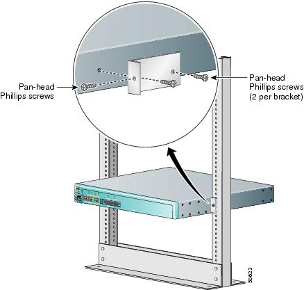
Step 4 ![]() Secure the bracket to IDS-4210 chassis using two screws (see Figure 2-3).
Secure the bracket to IDS-4210 chassis using two screws (see Figure 2-3).
Step 5 ![]() Repeat Step 4 to install the remaining bracket on the other side of IDS-4210.
Repeat Step 4 to install the remaining bracket on the other side of IDS-4210.
Step 6 ![]() Lift IDS-4210 into position between the two posts with the hole in the mounting bracket aligned one hole above the mark you made in the two posts (see Figure 2-3).
Lift IDS-4210 into position between the two posts with the hole in the mounting bracket aligned one hole above the mark you made in the two posts (see Figure 2-3).
Step 7 ![]() Secure IDS-4210 to the rack using a screw through the mounting bracket to the front of the left and right posts (see Figure 2-3).
Secure IDS-4210 to the rack using a screw through the mounting bracket to the front of the left and right posts (see Figure 2-3).
Installing Front Mount Brackets
Make sure you have the following supplies (found in the front mount bracket assembly kit) and tools to install the front mount brackets in a two-post, open-frame relay rack:
•![]() Two chassis support brackets
Two chassis support brackets
•![]() Two rack-mounting brackets
Two rack-mounting brackets
•![]() Six screws
Six screws
•![]() #2 Phillips screwdriver
#2 Phillips screwdriver
Note ![]() The front mount bracket assembly is not intended for use as a slide rail system. The server must be firmly attached to the rack, as shown in Figure 2-4.
The front mount bracket assembly is not intended for use as a slide rail system. The server must be firmly attached to the rack, as shown in Figure 2-4.
Figure 2-4 Front Mount Brackets

To install the front mount brackets, follow these steps:
Step 1 ![]() Make sure IDS-4210 is turned off and is not plugged in to an electrical outlet.
Make sure IDS-4210 is turned off and is not plugged in to an electrical outlet.
Step 2 ![]() Use the screws provided to attach one chassis support bracket to each side of IDS-4210. Use three screws on each side.
Use the screws provided to attach one chassis support bracket to each side of IDS-4210. Use three screws on each side.
Step 3 ![]() Use the screws provided with the rack to attach the rack mounting brackets to the rack.
Use the screws provided with the rack to attach the rack mounting brackets to the rack.
Step 4 ![]() Slide the chassis support brackets on IDS-4210 into the rack mounting brackets attached to the rack.
Slide the chassis support brackets on IDS-4210 into the rack mounting brackets attached to the rack.
Step 5 ![]() Use the bolts provided with the rack to fasten the front flanges of IDS-4210 to the rack.
Use the bolts provided with the rack to fasten the front flanges of IDS-4210 to the rack.
Note ![]() When you are done, IDS-4210 should not slide on the channel bar.
When you are done, IDS-4210 should not slide on the channel bar.
 Feedback