Cisco Intrusion Prevention System Appliance and Module Installation Guide for IPS 5.1
Bias-Free Language
The documentation set for this product strives to use bias-free language. For the purposes of this documentation set, bias-free is defined as language that does not imply discrimination based on age, disability, gender, racial identity, ethnic identity, sexual orientation, socioeconomic status, and intersectionality. Exceptions may be present in the documentation due to language that is hardcoded in the user interfaces of the product software, language used based on RFP documentation, or language that is used by a referenced third-party product. Learn more about how Cisco is using Inclusive Language.
- Updated:
- November 17, 2006
Chapter: Installing IDS-4215
- Introducing IDS-4215
- Front and Back Panel Features
- Specifications
- Accessories
- Surface Mounting
- Rack Mounting
- Installing IDS-4215
- Upgrading the BIOS and ROMMON
- Removing and Replacing the Chassis Cover
- Removing and Replacing the IDE Hard-Disk Drive
- Removing and Replacing the Compact Flash Device
- Removing and Installing the 4FE Card
Installing IDS-4215
This chapter describes IDS-4215 and how to install it. It also describes the accessories and how to install them. This chapter contains the following sections:
•![]() Front and Back Panel Features
Front and Back Panel Features
•![]() Upgrading the BIOS and ROMMON
Upgrading the BIOS and ROMMON
•![]() Removing and Replacing the Chassis Cover
Removing and Replacing the Chassis Cover
•![]() Removing and Replacing the IDE Hard-Disk Drive
Removing and Replacing the IDE Hard-Disk Drive
•![]() Removing and Replacing the Compact Flash Device
Removing and Replacing the Compact Flash Device
•![]() Removing and Installing the 4FE Card
Removing and Installing the 4FE Card
 |
Warning |
Introducing IDS-4215
IDS-4215 can monitor up to 80 Mbps of aggregate traffic and is suitable for T1/E1 and T3 environments. With the addition of the four-port fast Ethernet (4FE) card, IDS-4215 supports five sensing interfaces (10/100BASE-TX), which provide simultaneous protection for multiple subnets.

Note ![]() The 80-Mbps performance for IDS-4215 is based on the following conditions: aggregation of traffic from all five sensing interfaces, 800 new TCP connections per second, 800 HTTP transactions per second, average packet size of 445 bytes, and system running Cisco IPS 5.1 software.
The 80-Mbps performance for IDS-4215 is based on the following conditions: aggregation of traffic from all five sensing interfaces, 800 new TCP connections per second, 800 HTTP transactions per second, average packet size of 445 bytes, and system running Cisco IPS 5.1 software.
The sensing interfaces and the command and control interface are all 10/100BASE-TX.
Front and Back Panel Features
This section describes the IDS-4215 front and back panel features and indicators.
Figure 3-1 shows the front view of IDS-4215.
Figure 3-1 IDS-4215 Front Panel Features
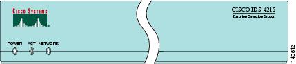
Table 3-1 describes the front panel indicators on IDS-4215.
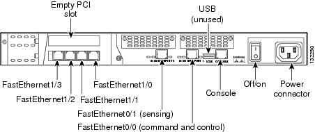
Figure 3-2 shows the back view of IDS-4215.
Figure 3-2 IDS-4215 Back Panel Features
|
Warning |
The built-in Ethernet ports have three indicators per port and the 4FE card has two indicators per port. Figure 3-3 shows the back panel indicators.
Figure 3-3 IDS-4215
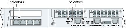
Table 3-2 lists the back panel indicators.
Specifications
Table 3-3 lists the specifications for IDS-4215.
Note ![]() Only one PCI expansion slot can be used for the 4FE card. We recommend you install the 4FE card in the lower PCI expansion slot.
Only one PCI expansion slot can be used for the 4FE card. We recommend you install the 4FE card in the lower PCI expansion slot.
Accessories
|
Warning |
IDS-4215 accessories kit contains the following:
•![]() DB25F/RJ45F adaptor
DB25F/RJ45F adaptor
•![]() DB9F/RJ45F adaptor
DB9F/RJ45F adaptor
•![]() Rubber mounting feet
Rubber mounting feet
•![]() Rack mounting kit—screws, washers, and metal bracket
Rack mounting kit—screws, washers, and metal bracket
•![]() RJ45 console cable
RJ45 console cable
•![]() 6-ft Ethernet cable
6-ft Ethernet cable
Surface Mounting
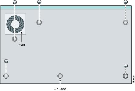
If you are not rack mounting IDS-4215, you must attach the rubber feet to the bottom of IDS-4215 as shown in Figure 3-4. The rubber feet are shipped in the accessories kit.
Figure 3-4 Surface Mounting IDS-4215

Rack Mounting
If you are installing the 4FE card in IDS-4215, do not install the mounting brackets until after you have installed the 4FE card.
Note ![]() You must remove the chassis cover of IDS-4215 to properly install or remove the 4FE card. For information on how to remove and replace the chassis cover, see Removing and Replacing the Chassis Cover. For information on installing the 4FE card in IDS-4215, see Installing the 4FE Card.
You must remove the chassis cover of IDS-4215 to properly install or remove the 4FE card. For information on how to remove and replace the chassis cover, see Removing and Replacing the Chassis Cover. For information on installing the 4FE card in IDS-4215, see Installing the 4FE Card.
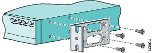
To rack mount IDS-4215, follow these steps:
Step 1 ![]() Use the supplied screws to attach the bracket to IDS-4215.
Use the supplied screws to attach the bracket to IDS-4215.
You can attach the brackets to the holes near the front of IDS-4215.
Step 2 ![]() Attach IDS-4215 to the equipment rack
Attach IDS-4215 to the equipment rack
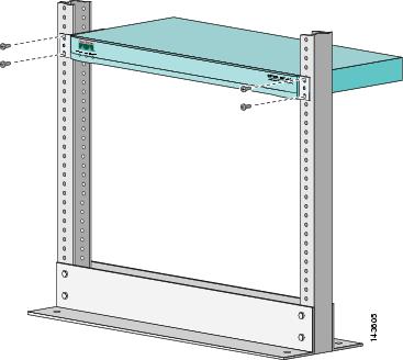
.
Installing IDS-4215
|
Warning |
To install IDS-4215 on the network, follow these steps:
Step 1 ![]() Position IDS-4215 on the network.
Position IDS-4215 on the network.
Step 2 ![]() Attach the power cord to IDS-4215 and plug it into a power source (a UPS is recommended).
Attach the power cord to IDS-4215 and plug it into a power source (a UPS is recommended).
Step 3 ![]() Connect the cable so that you have either a DB-9 or DB-25 connector on one end as required by the serial port for your computer, and the other end is the RJ-45 connector.
Connect the cable so that you have either a DB-9 or DB-25 connector on one end as required by the serial port for your computer, and the other end is the RJ-45 connector.
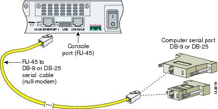
Note ![]() Use the console port to connect to a computer to enter configuration commands. Locate the serial cable from the accessory kit. The serial cable assembly consists of a 180/rollover cable with RJ-45 connectors (DB-9 connector adapter PN 74-0495-01 and DB-25 connector adapter PN 29-0810-01).
Use the console port to connect to a computer to enter configuration commands. Locate the serial cable from the accessory kit. The serial cable assembly consists of a 180/rollover cable with RJ-45 connectors (DB-9 connector adapter PN 74-0495-01 and DB-25 connector adapter PN 29-0810-01).
Note ![]() You can use a 180/rollover or straight-through patch cable to connect IDS-4215 to a port on a terminal server with RJ-45 or hydra cable assembly connections. Connect the appropriate cable from the console port on IDS-4215 to a port on the terminal server. For the instructions for setting up a terminal server, see Setting Up a Terminal Server.
You can use a 180/rollover or straight-through patch cable to connect IDS-4215 to a port on a terminal server with RJ-45 or hydra cable assembly connections. Connect the appropriate cable from the console port on IDS-4215 to a port on the terminal server. For the instructions for setting up a terminal server, see Setting Up a Terminal Server.
Step 4 ![]() Connect the RJ-45 connector to the console port and connect the other end to the serial port connector on your computer.
Connect the RJ-45 connector to the console port and connect the other end to the serial port connector on your computer.
Step 5 ![]() Attach the network cables.
Attach the network cables.
IDS-4215 has the following interfaces:
•![]() FastEthernet0/0 is the command and control port.
FastEthernet0/0 is the command and control port.
•![]() FastEthernet0/1 is the sensing port.
FastEthernet0/1 is the sensing port.
•![]() FastEthernet1/0, FastEthernet1/1, FastEthernet1/2, and FastEthernet1/3 are the optional sensing ports available if you have the 4FE card installed.
FastEthernet1/0, FastEthernet1/1, FastEthernet1/2, and FastEthernet1/3 are the optional sensing ports available if you have the 4FE card installed.
Step 6 ![]() Power on IDS-4215.
Power on IDS-4215.
Make sure the BIOS version is 5.1.7 and the ROMMON version is 1.4 before upgrading IDS-4215 to 5.x. For the procedure, see Upgrading the BIOS and ROMMON.
Note ![]() The BIOS/ROMMON upgrade is necessary to install the 4.1(4) system image, but not the 5.0(2) system image. The 5.0(2) system image is smaller than the size limitation that applied to earlier versions of ROMMON, while the 4.1(4) system image was larger.
The BIOS/ROMMON upgrade is necessary to install the 4.1(4) system image, but not the 5.0(2) system image. The 5.0(2) system image is smaller than the size limitation that applied to earlier versions of ROMMON, while the 4.1(4) system image was larger.
Step 7 ![]() Initialize IDS-4215.
Initialize IDS-4215.
For the procedure, see Initializing the Sensor.
Step 8 ![]() Upgrade IDS-4215 to the most recent Cisco IPS software.
Upgrade IDS-4215 to the most recent Cisco IPS software.
For the procedure, see Obtaining Cisco IPS Software.
You are now ready to configure intrusion prevention on IDS-4215.
For More Information
•![]() For the procedure for using HTTPS to log in to IDM, refer to Logging In to IDM.
For the procedure for using HTTPS to log in to IDM, refer to Logging In to IDM.
•![]() For the procedures for configuring intrusion prevention on your sensor, refer to the following documents:
For the procedures for configuring intrusion prevention on your sensor, refer to the following documents:
–![]() Installing and Using Cisco Intrusion Prevention System Device Manager 5.1
Installing and Using Cisco Intrusion Prevention System Device Manager 5.1
–![]() Configuring the Cisco Intrusion Prevention System Sensor Using the Command Line Interface 5.1
Configuring the Cisco Intrusion Prevention System Sensor Using the Command Line Interface 5.1
Upgrading the BIOS and ROMMON
Some TFTP servers limit the maximum file size that can be transferred to ~32 MB. Therefore, we recommend the following TFTP servers:
•![]() For Windows:
For Windows:
Tftpd32 version 2.0, available at:
•![]() For UNIX:
For UNIX:
Tftp-hpa series, available at:
http://www.kernel.org/pub/software/network/tftp/
The BIOS/ROMMON upgrade utility (IDS-4215-bios-5.1.7-rom-1.4.bin) upgrades the BIOS of IDS-4215 to version 5.1.7 and the ROMMON to version 1.4.
To upgrade the BIOS and ROMMON on IDS-4215, follow these steps:
Step 1 ![]() Download the BIOS ROMMON upgrade utility (IDS-4215-bios-5.1.7-rom-1.4.bin) to the TFTP root directory of a TFTP server that is accessible from IDS-4215.
Download the BIOS ROMMON upgrade utility (IDS-4215-bios-5.1.7-rom-1.4.bin) to the TFTP root directory of a TFTP server that is accessible from IDS-4215.
For the procedure for locating software on Cisco.com, see Obtaining Cisco IPS Software.
Note ![]() Make sure you can access the TFTP server location from the network connected to the Ethernet port of IDS-4215.
Make sure you can access the TFTP server location from the network connected to the Ethernet port of IDS-4215.
Step 2 ![]() Boot IDS-4215.
Boot IDS-4215.
While rebooting, IDS-4215 runs the BIOS POST. After the completion of POST, the console displays the message: Evaluating Run Options ...for about 5 seconds.
Step 3 ![]() Press Ctrl-R while this message is displayed to display the ROMMON menu.
Press Ctrl-R while this message is displayed to display the ROMMON menu.
The console display resembles the following:
CISCO SYSTEMS IDS-4215
Embedded BIOS Version 5.1.3 05/12/03 10:18:14.84
Compiled by ciscouser
Evaluating Run Options ...
Cisco ROMMON (1.2) #0: Mon May 12 10:21:46 MDT 2003
Platform IDS-4215
0: i8255X @ PCI(bus:0 dev:13 irq:11)
1: i8255X @ PCI(bus:0 dev:14 irq:11)
Using 1: i82557 @ PCI(bus:0 dev:14 irq:11), MAC: 0000.c0ff.ee01
Use ? for help.
rommon>
Step 4 ![]() If necessary, change the port number used for the TFTP download:
If necessary, change the port number used for the TFTP download:
rommon> interface port_number
The port in use is listed just before the rommon prompt. Port 1 (default port) is being used as indicated by the text, Using 1: i82557 @ PCI(bus:0 dev:14 irq:11), MAC: 0000.c0ff.ee01.
Note ![]() Ports 0 (monitoring port) and 1 (command and control port) are labeled on the back of the chassis.
Ports 0 (monitoring port) and 1 (command and control port) are labeled on the back of the chassis.
Step 5 ![]() Specify an IP address for the local port on IDS-4215:
Specify an IP address for the local port on IDS-4215:
rommon> address ip_address
Note ![]() Use the same IP address that is assigned to IDS-4215.
Use the same IP address that is assigned to IDS-4215.
Step 6 ![]() Specify the TFTP server IP address:
Specify the TFTP server IP address:
rommon> server ip_address
Step 7 ![]() Specify the gateway IP address:
Specify the gateway IP address:
rommon> gateway ip_address
Step 8 ![]() Verify that you have access to the TFTP server by pinging it from the local Ethernet port:
Verify that you have access to the TFTP server by pinging it from the local Ethernet port:
rommon> ping server_ip_address
rommon> ping server
Step 9 ![]() Specify the filename on the TFTP file server from which you are downloading the image:
Specify the filename on the TFTP file server from which you are downloading the image:
rommon> file filename
Example:
rommon> file IDS-4215-bios-5.1.7-rom-1.4.bin
Note ![]() The syntax of the file location depends on the type of TFTP server used. Contact your system or network administrator for the appropriate syntax if the above format does not work.
The syntax of the file location depends on the type of TFTP server used. Contact your system or network administrator for the appropriate syntax if the above format does not work.
Step 10 ![]() Download and run the update utility:
Download and run the update utility:
rommon> tftp
Step 11 ![]() Type y at the upgrade prompt and the update is executed.
Type y at the upgrade prompt and the update is executed.
IDS-4215 reboots when the update is complete.
Removing and Replacing the Chassis Cover
|
Warning |
This section describes how to remove and replace IDS-4215 chassis cover.
This section contains the following topics:
Removing the Chassis Cover
Note ![]() Removing the appliance chassis cover does not affect your Cisco warranty. Upgrading IDS-4215 does not require any special tools and does not create any radio frequency leaks.
Removing the appliance chassis cover does not affect your Cisco warranty. Upgrading IDS-4215 does not require any special tools and does not create any radio frequency leaks.
To remove the chassis cover, follow these steps:
Step 1 ![]() Log in to the CLI.
Log in to the CLI.
Step 2 ![]() Prepare IDS-4215 to be powered off:
Prepare IDS-4215 to be powered off:
sensor# reset powerdown
Wait for the power down message before continuing with Step 3.
Note ![]() You can also power down IDS-4215 using IDM.
You can also power down IDS-4215 using IDM.
Step 3 ![]() Power off IDS-4215.
Power off IDS-4215.
Step 4 ![]() Remove the power cord and other cables from IDS-4215.
Remove the power cord and other cables from IDS-4215.
Step 5 ![]() Place IDS-4215 in an ESD-controlled environment.
Place IDS-4215 in an ESD-controlled environment.
For more information, see Working in an ESD Environment.
Step 6 ![]() Remove the screws from the back of the chassis.
Remove the screws from the back of the chassis.
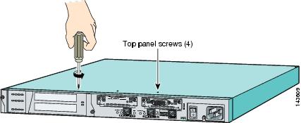
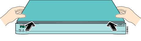
Step 7 ![]() With the front of IDS-4215 facing you, push the top panel back one inch.
With the front of IDS-4215 facing you, push the top panel back one inch.
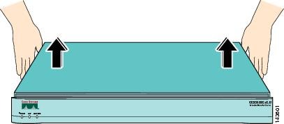
Step 8 ![]() Pull the top panel up and put it in a safe place.
Pull the top panel up and put it in a safe place.
Replacing the Chassis Cover
To replace the chassis cover, follow these steps:
Step 1 ![]() Place the chassis on a secure surface with the front panel facing you.
Place the chassis on a secure surface with the front panel facing you.
Step 2 ![]() Hold the top panel so the tabs at the rear of the top panel are aligned with the chassis bottom.
Hold the top panel so the tabs at the rear of the top panel are aligned with the chassis bottom.
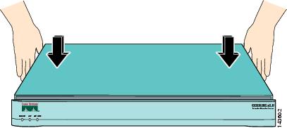
Step 3 ![]() Lower the front of the top panel onto the chassis, making sure that the top panel side tabs fit under the chassis side panels.
Lower the front of the top panel onto the chassis, making sure that the top panel side tabs fit under the chassis side panels.
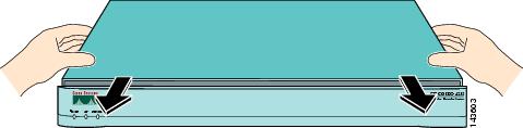
Step 4 ![]() Slide the top panel toward the front, making sure that the top panel tabs fit under the chassis back panel and the back panel tabs fit under the top panel.
Slide the top panel toward the front, making sure that the top panel tabs fit under the chassis back panel and the back panel tabs fit under the top panel.
Step 5 ![]() Fasten the top panel with the screws you set aside earlier.
Fasten the top panel with the screws you set aside earlier.
Step 6 ![]() Reinstall the chassis on a rack, desktop, or table.
Reinstall the chassis on a rack, desktop, or table.
If you are reinstalling in a rack, see Rack Mounting.
Step 7 ![]() Reinstall the network interface cables.
Reinstall the network interface cables.
For the procedure, see Installing IDS-4215.
Removing and Replacing the IDE Hard-Disk Drive
|
Warning |
This section describes how to remove and replace the IDE hard-disk drive. It contains the following topics:
•![]() Replacing the Hard-Disk Drive
Replacing the Hard-Disk Drive
Removing the Hard-Disk Drive
To remove the hard-disk drive from IDS-4215, follow these steps:
Step 1 ![]() Log in to the CLI.
Log in to the CLI.
Step 2 ![]() Prepare IDS-4215 to be powered off:
Prepare IDS-4215 to be powered off:
sensor# reset powerdown
Wait for the power down message before continuing with Step 3.
Note ![]() You can also power down IDS-4215 using IDM.
You can also power down IDS-4215 using IDM.
Step 3 ![]() Power off IDS-4215.
Power off IDS-4215.
Step 4 ![]() Remove the power cord and other cables from IDS-4215.
Remove the power cord and other cables from IDS-4215.
Step 5 ![]() Place IDS-4215 in an ESD-controlled environment.
Place IDS-4215 in an ESD-controlled environment.
For more information, see Working in an ESD Environment.
Step 6 ![]() Remove the chassis cover.
Remove the chassis cover.
For the procedure, see Removing the Chassis Cover.
Step 7 ![]() Loosen the two captive screws from the hard-disk drive carrier.
Loosen the two captive screws from the hard-disk drive carrier.
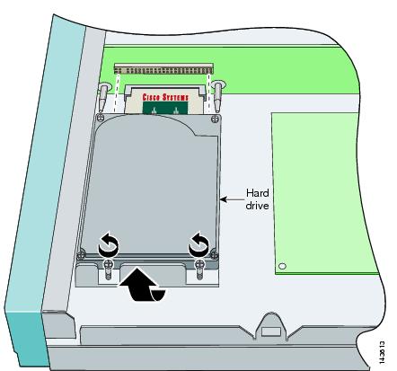
Step 8 ![]() Grasp the hard-disk drive and pull straight backwards until it is free of the riser card connector. Do not lift or wiggle the hard-disk drive side to side until it is completely free of the connector.
Grasp the hard-disk drive and pull straight backwards until it is free of the riser card connector. Do not lift or wiggle the hard-disk drive side to side until it is completely free of the connector.
Replacing the Hard-Disk Drive
To replace the hard-disk drive in IDS-4215, follow these steps:
Step 1 ![]() Place IDS-4215 in an ESD-controlled environment.
Place IDS-4215 in an ESD-controlled environment.
For more information, see Working in an ESD Environment.
Step 2 ![]() Align the hard-disk drive connector with the two guide pins on the riser card.
Align the hard-disk drive connector with the two guide pins on the riser card.
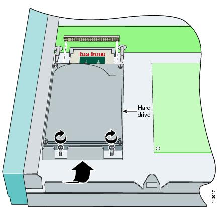
Step 3 ![]() Push the hard-disk drive straight into the riser card connector. Do not lift or wiggle the hard-disk drive side to side. Push carefully until the hard-disk drive is seated.
Push the hard-disk drive straight into the riser card connector. Do not lift or wiggle the hard-disk drive side to side. Push carefully until the hard-disk drive is seated.
Step 4 ![]() Tighten the two captive screws.
Tighten the two captive screws.
Step 5 ![]() Replace the chassis cover.
Replace the chassis cover.
For the procedure, see Replacing the Chassis Cover.
Removing and Replacing the Compact Flash Device
|
Warning |
This section describes how to remove and replace the compact flash device in IDS-4215, and contains the following topics:
•![]() Removing the Compact Flash Device
Removing the Compact Flash Device
•![]() Replacing the Compact Flash Device
Replacing the Compact Flash Device
Removing the Compact Flash Device
To remove the compact flash device from IDS-4215, follow these steps:
Step 1 ![]() Log in to the CLI.
Log in to the CLI.
Step 2 ![]() Prepare IDS-4215 to be powered off:
Prepare IDS-4215 to be powered off:
sensor# reset powerdown
Wait for the power down message before continuing with Step 3.
Note ![]() You can also power down IDS-4215 using IDM.
You can also power down IDS-4215 using IDM.
Step 3 ![]() Power off IDS-4215.
Power off IDS-4215.
Step 4 ![]() Remove the power cord and other cables from IDS-4215.
Remove the power cord and other cables from IDS-4215.
Step 5 ![]() Place IDS-4215 in an ESD-controlled environment.
Place IDS-4215 in an ESD-controlled environment.
For more information, see Working in an ESD Environment.
Step 6 ![]() Remove the chassis cover.
Remove the chassis cover.
For the procedure, see Removing the Chassis Cover.
Step 7 ![]() Remove the hard-disk drive.
Remove the hard-disk drive.
For the procedure, see Removing the Hard-Disk Drive.
Step 8 ![]() Grasp the compact flash device and carefully remove it from the connector on the riser card.
Grasp the compact flash device and carefully remove it from the connector on the riser card.

Replacing the Compact Flash Device
To replace the compact flash device in IDS-4215, follow these steps:
Step 1 ![]() Place IDS-4215 in an ESD-controlled environment.
Place IDS-4215 in an ESD-controlled environment.
For more information, see Working in an ESD Environment.
Step 2 ![]() Align the compact flash device with the connector on the riser card.
Align the compact flash device with the connector on the riser card.
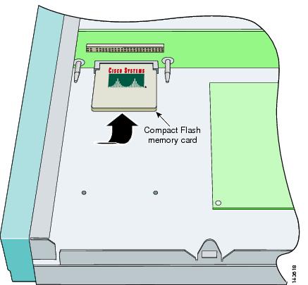
Step 3 ![]() Press until the compact flash device is fully seated in the connector.
Press until the compact flash device is fully seated in the connector.
Step 4 ![]() Replace the hard-disk drive.
Replace the hard-disk drive.
For the procedure, see Replacing the Hard-Disk Drive.
Step 5 ![]() Replace the chassis cover.
Replace the chassis cover.
For the procedure, see Replacing the Chassis Cover.
Removing and Installing the 4FE Card
|
Warning |
You can order IDS-4215 with the 4FE card already installed or you can upgrade IDS-4215 with the 4FE card to have four additional interfaces.
This section contains the following topics:
Removing the 4FE Card
To remove the 4FE card, follow these steps:
Step 1 ![]() Log in to the CLI.
Log in to the CLI.
Step 2 ![]() Prepare IDS-4215 to be powered off:
Prepare IDS-4215 to be powered off:
sensor# reset powerdown
Wait for the power down message before continuing with Step 3.
Note ![]() You can also power down IDS-4215 using IDM.
You can also power down IDS-4215 using IDM.
Step 3 ![]() Power off IDS-4215.
Power off IDS-4215.
Step 4 ![]() Remove the power cord and other cables from IDS-4215.
Remove the power cord and other cables from IDS-4215.
Step 5 ![]() Place IDS-4215 in an ESD-controlled environment.
Place IDS-4215 in an ESD-controlled environment.
For more information, see Working in an ESD Environment.
Step 6 ![]() Remove the chassis cover.
Remove the chassis cover.
For the procedure, see Removing the Chassis Cover.
Step 7 ![]() Loosen the single captive screw that holds the 4FE card's connecting flange to the back cover plate.
Loosen the single captive screw that holds the 4FE card's connecting flange to the back cover plate.
Step 8 ![]() Loosen the two captive screws from the back cover on the left and put the back cover aside.
Loosen the two captive screws from the back cover on the left and put the back cover aside.
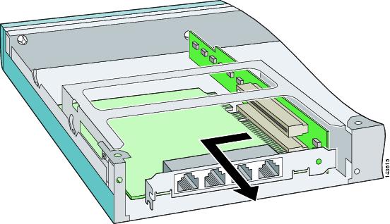
Step 9 ![]() Grasp the 4FE card and pull it out of the slot and through the cage opening.
Grasp the 4FE card and pull it out of the slot and through the cage opening.
Step 10 ![]() Replace the lower slot cover from the back cover plate.
Replace the lower slot cover from the back cover plate.
Step 11 ![]() Replace the back cover plate and tighten the two captive screws.
Replace the back cover plate and tighten the two captive screws.
Step 12 ![]() Replace the chassis cover.
Replace the chassis cover.
For the procedure, see Replacing the Chassis Cover.
Installing the 4FE Card
We recommend that you install the 4FE card in the bottom slot. We do not support installation of the 4FE card in the top slot.
Note ![]() Only one 4FE card is supported on IDS-4215.
Only one 4FE card is supported on IDS-4215.
To install a 4FE card in IDS-4215, follow these steps:
Step 1 ![]() Prepare IDS-4215 to be powered off:
Prepare IDS-4215 to be powered off:
sensor# reset powerdown
Wait for the power down message before continuing with Step 2.
Step 2 ![]() Power off IDS-4215.
Power off IDS-4215.
Step 3 ![]() Remove the power cord and other cables from IDS-4215.
Remove the power cord and other cables from IDS-4215.
Step 4 ![]() Place IDS-4215 in an ESD-controlled environment.
Place IDS-4215 in an ESD-controlled environment.
For more information, see Working in an ESD Environment.
Step 5 ![]() Remove the chassis cover.
Remove the chassis cover.
For the procedure, see Removing the Chassis Cover.
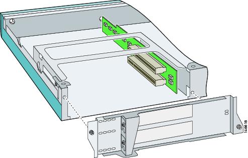
Step 6 ![]() Loosen the two captive screws from the back cover plate on the left and put the back cover plate aside.
Loosen the two captive screws from the back cover plate on the left and put the back cover plate aside.
Step 7 ![]() Insert the 4FE card through the cage opening and into the lower slot.
Insert the 4FE card through the cage opening and into the lower slot.
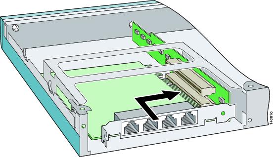
Note ![]() When you insert a 4FE card in the slot, the end of the card's connector extends past the end of the slot. This does not affect the use or operation of the card.
When you insert a 4FE card in the slot, the end of the card's connector extends past the end of the slot. This does not affect the use or operation of the card.
Step 8 ![]() Remove the lower slot cover from the back cover plate.
Remove the lower slot cover from the back cover plate.
Step 9 ![]() Attach the back cover plate making sure that the connecting flange on the 4FE card goes through the slot on the back cover plate.
Attach the back cover plate making sure that the connecting flange on the 4FE card goes through the slot on the back cover plate.
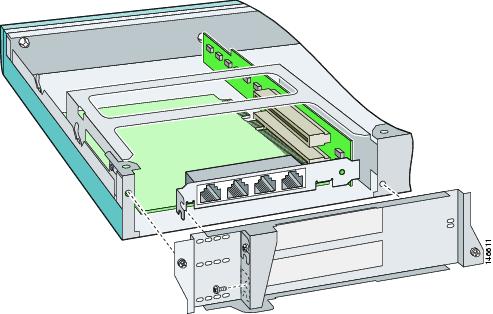
Step 10 ![]() Tighten the single captive screw to hold the 4FE card's connecting flange to the back cover plate, and tighten the captive screws to attach the back cover plate to the appliance.
Tighten the single captive screw to hold the 4FE card's connecting flange to the back cover plate, and tighten the captive screws to attach the back cover plate to the appliance.
Step 11 ![]() Replace the chassis cover.
Replace the chassis cover.
For the procedure, see Replacing the Chassis Cover.
You will need to assign the new interfaces (FastEthernet1/0, FastEthernet1/1, FastEthernet1/2, and FastEthernet1/3). For the CLI procedure, refer to Configuring Interfaces. For the IDM procedure, refer to Configuring Interfaces.
 Feedback