Interfaces for Firepower Threat Defense

This chapter includes FTD interface configuration including Ethernet settings, EtherChannels, VLAN subinterfaces, IP addressing, and more.


Note

For initial interface configuration on the Firepower 4100/9300, see Configure Interfaces.


About FTD Interfaces

The FTD device includes data interfaces that you can configure in different modes, as well as a management/diagnostic interface.

Management/Diagnostic Interface and Network Deployment

The physical management interface is shared between the Diagnostic logical interface and the Management logical interface.

Management Interface

The Management logical interface is separate from the other interfaces on the device. It is used to set up and register the device to the Firepower Management Center. It uses its own IP address and static routing. You can configure its settings at the CLI using the configure network command. If you change the IP address at the CLI after you add it to the Firepower Management Center, you can match the IP address in the Firepower Management Center in the Devices > Device Management > Devices > Management area.

Diagnostic Interface

The Diagnostic logical interface can be configured along with the rest of the data interfaces on the Devices > Device Management > Interfaces screen. Using the Diagnostic interface is optional (see the routed and transparent mode deployments for scenarios). The Diagnostic interface only allows management traffic, and does not allow through traffic. It does not support SSH; you can SSH to data interfaces or to the Management interface only. The Diagnostic interface is useful for SNMP or syslog monitoring.

Routed Mode Deployment

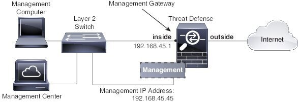
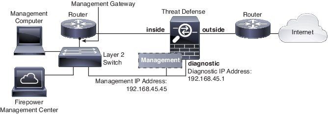
We recommend that you do not configure an IP address for the Diagnostic interface if you do not have an inside router. The benefit to leaving the IP address off of the Diagnostic interface is that you can place the Management interface on the same network as any other data interfaces. If you configure the Diagnostic interface, its IP address is typically on the same network as the Management IP address, and it counts as a regular interface that cannot be on the same network as any other data interfaces. Because the Management interface requires Internet access for updates, putting Management on the same network as an inside interface means you can deploy the FTD device with only a switch on the inside and point to the inside interface as its gateway. See the following deployment that uses an inside switch:


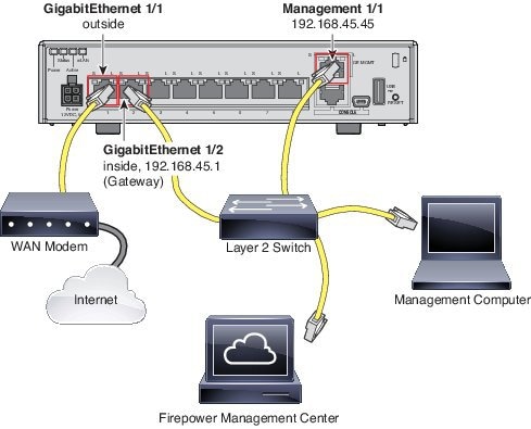
To cable the above scenario on the ASA 5506-X, ASA 5508-X, or ASA 5516-X, see the following:

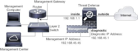
If you configure the Diagnostic IP address, then you need an inside router:


Transparent Mode Deployment

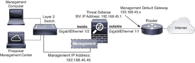
Like the routed mode deployment, you can choose to deploy the device with an inside switch, in which case you need to keep the Diagnostic interface without an IP address:

Or you can deploy with an inside router, in which case you can use the Diagnostic interface with an IP address for additional management access:

Interface Mode and Types

You can deploy FTD interfaces in two modes: Regular firewall mode and IPS-only mode. You can include both firewall and IPS-only interfaces on the same device.

Regular Firewall Mode

Firewall mode interfaces subject traffic to firewall functions such as maintaining flows, tracking flow states at both IP and TCP layers, IP defragmentation, and TCP normalization. You can also optionally configure IPS functions for this traffic according to your security policy.

The types of firewall interfaces you can configure depends on the firewall mode set for the device: routed or transparent mode. See Transparent or Routed Firewall Mode for Firepower Threat Defense for more information.

  • Routed mode interfaces (routed firewall mode only)—Each interface that you want to route between is on a different subnet.

  • Bridge group interfaces (routed and transparent firewall mode)—You can group together multiple interfaces on a network, and the Firepower Threat Defense device uses bridging techniques to pass traffic between the interfaces. Each bridge group includes a Bridge Virtual Interface (BVI) to which you assign an IP address on the network. In routed mode, the Firepower Threat Defense device routes between BVIs and regular routed interfaces. In transparent mode, each bridge group is separate and cannot communicate with each other.

IPS-Only Mode

IPS-only mode interfaces bypass many firewall checks and only support IPS security policy. You might want to implement IPS-only interfaces if you have a separate firewall protecting these interfaces and do not want the overhead of firewall functions.


Note

The firewall mode only affects regular firewall interfaces, and not IPS-only interfaces such as inline sets or passive interfaces. IPS-only interfaces can be used in both firewall modes.


IPS-only interfaces can be deployed as the following types:

  • Inline Set, with optional Tap mode—An inline set acts like a bump on the wire, and binds two interfaces together to slot into an existing network. This function allows the system to be installed in any network environment without the configuration of adjacent network devices. Inline interfaces receive all traffic unconditionally, but all traffic received on these interfaces is retransmitted out of an inline set unless explicitly dropped.

    With tap mode, the device is deployed inline, but instead of the packet flow passing through the device, a copy of each packet is sent to the device and the network traffic flow is undisturbed. However, rules of these types do generate intrusion events when they are triggered, and the table view of intrusion events indicates that the triggering packets would have dropped in an inline deployment. There are benefits to using tap mode with devices that are deployed inline. For example, you can set up the cabling between the device and the network as if the device were inline and analyze the kinds of intrusion events the device generates. Based on the results, you can modify your intrusion policy and add the drop rules that best protect your network without impacting its efficiency. When you are ready to deploy the device inline, you can disable tap mode and begin dropping suspicious traffic without having to reconfigure the cabling between the device and the network.


    Note

    Inline sets might be familiar to you as "transparent inline sets," but the inline interface type is unrelated to the transparent firewall mode or the firewall-type interfaces.


  • Passive or ERSPAN Passive—Passive interfaces monitor traffic flowing across a network using a switch SPAN or mirror port. The SPAN or mirror port allows for traffic to be copied from other ports on the switch. This function provides the system visibility within the network without being in the flow of network traffic. When configured in a passive deployment, the system cannot take certain actions such as blocking or shaping traffic. Passive interfaces receive all traffic unconditionally and no traffic received on these interfaces is retransmitted. Encapsulated remote switched port analyzer (ERSPAN) interfaces allow you to monitor traffic from source ports distributed over multiple switches, and uses GRE to encapsulate the traffic. ERSPAN interfaces are only allowed when the device is in routed firewall mode.

Security Zones and Interface Groups

Each interface must be assigned to a security zone and/or interface group. You then apply your security policy based on zones or groups. For example, you can assign the inside interface to the inside zone; and the outside interface to the outside zone. You can configure your access control policy to enable traffic to go from inside to outside, but not from outside to inside, for example. Some policies only support security zones, while other policies support zones and groups. For specifics, see Interface Objects: Interface Groups and Security Zones. You can create security zones and interface groups on the Objects page. You can also add a zone when you are configuring the interface. You can only add interfaces to the correct zone type for your interface, either Passive, Inline, Routed, or Switched zone types.

The Diagnostic/Management interface does not belong to a zone or interface group.


Note

Create inline sets before you add security zones for the interfaces in the inline set; otherwise security zones are removed and you must add them again.


Auto-MDI/MDIX Feature

For RJ-45 interfaces, the default auto-negotiation setting also includes the Auto-MDI/MDIX feature. Auto-MDI/MDIX eliminates the need for crossover cabling by performing an internal crossover when a straight cable is detected during the auto-negotiation phase. Either the speed or duplex must be set to auto-negotiate to enable Auto-MDI/MDIX for the interface. If you explicitly set both the speed and duplex to a fixed value, thus disabling auto-negotiation for both settings, then Auto-MDI/MDIX is also disabled. For Gigabit Ethernet, when the speed and duplex are set to 1000 and full, then the interface always auto-negotiates; therefore Auto-MDI/MDIX is always enabled and you cannot disable it.

Configure a Regular (Firewall) Mode Interface

For regular interfaces, you can configure physical interfaces and also create redundant interfaces, EtherChannel interfaces, and VLAN subinterfaces. You can configure routed or bridged interfaces.

Procedure


Step 1

For the FTD appliance, perform the following tasks. For the Firepower 4100/9300, you configure basic interface settings in FXOS. See Configure Interfaces for more information.

  1. Enable the Physical Interface and Configure Ethernet Settings

  2. (Optional) Configure a Redundant Interface

    You can configure a redundant interface to increase the FTD reliability.

  3. (Optional) Configure an EtherChannel

    An EtherChannel lets you combine multiple interfaces so you can increase the bandwidth for a single network, and also provide interface redundancy.

Step 2

(Optional) Configure VLAN Subinterfaces and 802.1Q Trunking.

VLAN subinterfaces let you divide a physical, redundant, or EtherChannel interface into multiple logical interfaces that are tagged with different VLAN IDs.

Step 3

Configure Routed Mode Interfaces or Configure Bridge Group Interfaces

Step 4

(Optional) Configure IPv6 Addressing

Step 5

(Optional) Perform Advanced Interface Configuration.

You can configure manual MAC addresses, the MTU, and other settings for interfaces.


Enable the Physical Interface and Configure Ethernet Settings

Smart License

Classic License

Supported Devices

Supported Domains

Access

Any

N/A

FTD

Any

Access Admin
Administrator
Network Admin

This section describes how to:

  • Enable the physical interface. By default, physical interfaces are disabled (with the exception of the Diagnostic interface).

  • Set a specific speed and duplex. By default, speed and duplex are set to Auto.

This procedure only covers a small subset of Interface settings. Refrain from setting other parameters at this point. For example, you cannot name an interface that you want to use as part of an EtherChannel or redundant interface.


Note

For the Firepower 4100/9300, you configure basic interface settings in FXOS. See Configure a Physical Interface for more information.


Before you begin

If you changed the physical interfaces on the device after you added it to the FMC, you need to refresh the interface listing by clicking the Sync Interfaces from device button on the top left of the Interfaces tab.

Procedure


Step 1

Select Devices > Device Management and click the edit icon () for your FTD device. The Interfaces tab is selected by default.

Step 2

Click the edit icon () for the interface you want to edit.

Step 3

In the Mode drop-down list, choose None.

Regular firewall interfaces have the mode set to None. The other modes are for IPS-only interface types.

Step 4

Enable the interface by checking the Enabled check box.

Step 5

(Optional) Add a description in the Description field.

The description can be up to 200 characters on a single line, without carriage returns.

Step 6

(Optional) Set the duplex and speed by clicking the Hardware Configuration tab.

  • Duplex—Choose Full, Half, or Auto. Auto is the default when the interface supports it.

  • Speed—Choose 10, 100, 1000, or Auto. Auto is the default. The type of interface limits the options you can select.

Step 7

Click OK.

Step 8

Click Save.

You can now click Deploy and deploy the policy to assigned devices. The changes are not active until you deploy them.


EtherChannel and Redundant Interfaces

This section tells how to configure EtherChannels and redundant interfaces.


Note

For the Firepower 4100/9300, you configure EtherChannels in FXOS. See Add an EtherChannel (Port Channel) for more information. Redundant interfaces are not supported.


About EtherChannels and Redundant Interfaces

This section describes EtherChannels and Redundant Interfaces.

Redundant Interfaces

A logical redundant interface consists of a pair of physical interfaces: an active and a standby interface. When the active interface fails, the standby interface becomes active and starts passing traffic. You can configure a redundant interface to increase the Firepower Threat Defense device reliability.

You can configure up to 8 redundant interface pairs.

Redundant Interface MAC Address

The redundant interface uses the MAC address of the first physical interface that you add. If you change the order of the member interfaces in the configuration, then the MAC address changes to match the MAC address of the interface that is now listed first. Alternatively, you can assign a manual MAC address to the redundant interface, which is used regardless of the member interface MAC addresses. When the active interface fails over to the standby, the same MAC address is maintained so that traffic is not disrupted.

EtherChannels

An 802.3ad EtherChannel is a logical interface (called a port-channel interface) consisting of a bundle of individual Ethernet links (a channel group) so that you increase the bandwidth for a single network. A port channel interface is used in the same way as a physical interface when you configure interface-related features.

You can configure up to 48 EtherChannels.

Channel Group Interfaces

Each channel group can have up to 16 active interfaces. For switches that support only 8 active interfaces, you can assign up to 16 interfaces to a channel group: while only 8 interfaces can be active, the remaining interfaces can act as standby links in case of interface failure. For 16 active interfaces, be sure that your switch supports the feature (for example, the Cisco Nexus 7000 with F2-Series 10 Gigabit Ethernet Module).

All interfaces in the channel group must be the same type and speed. The first interface added to the channel group determines the correct type and speed. Note that for interfaces that you can configure to use either the RJ-45 or SFP connector, you can include both RJ-45 and SFP interfaces in the same EtherChannel.

The EtherChannel aggregates the traffic across all the available active interfaces in the channel. The interface is selected using a proprietary hash algorithm, based on source or destination MAC addresses, IP addresses, TCP and UDP port numbers and VLAN numbers.

Connecting to an EtherChannel on Another Device

The device to which you connect the Firepower Threat Defense device EtherChannel must also support 802.3ad EtherChannels; for example, you can connect to the Catalyst 6500 switch or the Cisco Nexus 7000.

When the switch is part of a Virtual Switching System (VSS) or Virtual Port Channel (vPC), then you can connect Firepower Threat Defense device interfaces within the same EtherChannel to separate switches in the VSS/vPC. The switch interfaces are members of the same EtherChannel port-channel interface, because the separate switches act like a single switch.

Figure 1. Connecting to a VSS/vPC

If you use the Firepower Threat Defense device in an Active/Standby failover deployment, then you need to create separate EtherChannels on the switches in the VSS/vPC, one for each Firepower Threat Defense device. On each Firepower Threat Defense device, a single EtherChannel connects to both switches. Even if you could group all switch interfaces into a single EtherChannel connecting to both Firepower Threat Defense device (in this case, the EtherChannel will not be established because of the separate Firepower Threat Defense device system IDs), a single EtherChannel would not be desirable because you do not want traffic sent to the standby Firepower Threat Defense device.

Figure 2. Active/Standby Failover and VSS/vPC
Link Aggregation Control Protocol

The Link Aggregation Control Protocol (LACP) aggregates interfaces by exchanging the Link Aggregation Control Protocol Data Units (LACPDUs) between two network devices.

You can configure each physical interface in an EtherChannel to be:

  • Active—Sends and receives LACP updates. An active EtherChannel can establish connectivity with either an active or a passive EtherChannel. You should use the active mode unless you need to minimize the amount of LACP traffic.

  • Passive—Receives LACP updates. A passive EtherChannel can only establish connectivity with an active EtherChannel.

  • On—The EtherChannel is always on, and LACP is not used. An “on” EtherChannel can only establish a connection with another “on” EtherChannel.

LACP coordinates the automatic addition and deletion of links to the EtherChannel without user intervention. It also handles misconfigurations and checks that both ends of member interfaces are connected to the correct channel group. “On” mode cannot use standby interfaces in the channel group when an interface goes down, and the connectivity and configurations are not checked.

Load Balancing

The Firepower Threat Defense device distributes packets to the interfaces in the EtherChannel by hashing the source and destination IP address of the packet (this criteria is configurable). The resulting hash is divided by the number of active links in a modulo operation where the resulting remainder determines which interface owns the flow. All packets with a hash_value mod active_links result of 0 go to the first interface in the EtherChannel, packets with a result of 1 go to the second interface, packets with a result of 2 go to the third interface, and so on. For example, if you have 15 active links, then the modulo operation provides values from 0 to 14. For 6 active links, the values are 0 to 5, and so on.

If an active interface goes down and is not replaced by a standby interface, then traffic is rebalanced between the remaining links. The failure is masked from both Spanning Tree at Layer 2 and the routing table at Layer 3, so the switchover is transparent to other network devices.

EtherChannel MAC Address

All interfaces that are part of the channel group share the same MAC address. This feature makes the EtherChannel transparent to network applications and users, because they only see the one logical connection; they have no knowledge of the individual links.

The port-channel interface uses the lowest numbered channel group interface MAC address as the port-channel MAC address. Alternatively you can manually configure a MAC address for the port-channel interface. We recommend manually configuring a unique MAC address in case the group channel interface membership changes. If you remove the interface that was providing the port-channel MAC address, then the port-channel MAC address changes to the next lowest numbered interface, thus causing traffic disruption.

Guidelines for EtherChannels and Redundant Interfaces

Bridge Group

In routed mode, EtherChannels are not supported as bridge group members.

High Availability
  • When you use a redundant or EtherChannel interface as a High Availability link, it must be pre-configured on both units in the High Availability pair; you cannot configure it on the primary unit and expect it to replicate to the secondary unit because the High Availability link itself is required for replication.

  • If you use a redundant or EtherChannel interface for the state link, no special configuration is required; the configuration can replicate from the primary unit as normal.

  • You can monitor redundant or EtherChannel interfaces for High Availability. When an active member interface fails over to a standby interface, this activity does not cause the redundant or EtherChannel interface to appear to be failed when being monitored for device-level High Availability. Only when all physical interfaces fail does the redundant or EtherChannel interface appear to be failed (for an EtherChannel interface, the number of member interfaces allowed to fail is configurable).

  • If you use an EtherChannel interface for a High Availability or state link, then to prevent out-of-order packets, only one interface in the EtherChannel is used. If that interface fails, then the next interface in the EtherChannel is used. You cannot alter the EtherChannel configuration while it is in use as a High Availability link. To alter the configuration, you need to either shut down the EtherChannel while you make changes, or temporarily disable High Availability; either action prevents High Availability from occurring for the duration.

Model Support
  • EtherChannels are supported on Firepower Threat Defense device appliances only; they are not supported on the Firepower Threat Defense Virtual.

  • For the Firepower 4100/9300 chassis, you configure EtherChannels in FXOS, not in the Firepower Threat Defense device OS.

  • Redundant interfaces are not supported on the Firepower 4100/9300 chassis.

Redundant Interfaces
  • You can configure up to 8 redundant interface pairs.

  • All Firepower Threat Defense device configuration refers to the logical redundant interface instead of the member physical interfaces.

  • You cannot use a redundant interface as part of an EtherChannel, nor can you use an EtherChannel as part of a redundant interface. You cannot use the same physical interfaces in a redundant interface and an EtherChannel interface. You can, however, configure both types on the Firepower Threat Defense device if they do not use the same physical interfaces.

  • If you shut down the active interface, then the standby interface becomes active.

  • Redundant interfaces do not support Diagnostic slot/port interfaces as members. You can, however, set a redundant interface comprised of non-Diagnostic interfaces as management-only.

EtherChannels
  • EtherChannels are supported on Firepower Threat Defense device appliances only; they are not supported on the Firepower Threat Defense Virtual.

  • You can configure up to 48 EtherChannels.

  • Each channel group can have up to 16 active interfaces. For switches that support only 8 active interfaces, you can assign up to 16 interfaces to a channel group: while only eight interfaces can be active, the remaining interfaces can act as standby links in case of interface failure.

  • All interfaces in the channel group must be the same type and speed. The first interface added to the channel group determines the correct type and speed. Note that for interfaces that you can configure to use either the RJ-45 or SFP connector, you can include both RJ-45 and SFP interfaces in the same EtherChannel.

  • The device to which you connect the Firepower Threat Defense device EtherChannel must also support 802.3ad EtherChannels; for example, you can connect to the Catalyst 6500 switch or Cisco Nexus 7000 switch.

  • The Firepower Threat Defense device does not support LACPDUs that are VLAN-tagged. If you enable native VLAN tagging on the neighboring switch using the Cisco IOS vlan dot1Q tag native command, then the Firepower Threat Defense device will drop the tagged LACPDUs. Be sure to disable native VLAN tagging on the neighboring switch.

  • In Cisco IOS software versions earlier than 15.1(1)S2, the Firepower Threat Defense device did not support connecting an EtherChannel to a switch stack. With default switch settings, if the Firepower Threat Defense device EtherChannel is connected cross stack, and if the master switch is powered down, then the EtherChannel connected to the remaining switch will not come up. To improve compatibility, set the stack-mac persistent timer command to a large enough value to account for reload time; for example, 8 minutes or 0 for indefinite. Or, you can upgrade to more a more stable switch software version, such as 15.1(1)S2.

  • All Firepower Threat Defense device configuration refers to the logical EtherChannel interface instead of the member physical interfaces.

  • You cannot use a redundant interface as part of an EtherChannel, nor can you use an EtherChannel as part of a redundant interface. You cannot use the same physical interfaces in a redundant interface and an EtherChannel interface. You can, however, configure both types on the Firepower Threat Defense device if they do not use the same physical interfaces.

Configure a Redundant Interface

Smart License

Classic License

Supported Devices

Supported Domains

Access

Any

N/A

FTD

Any

Access Admin
Administrator
Network Admin

A logical redundant interface consists of a pair of physical interfaces: an active and a standby interface. When the active interface fails, the standby interface becomes active and starts passing traffic. You can configure a redundant interface to increase the FTD reliability. By default, redundant interfaces are enabled.

  • You can configure up to 8 redundant interface pairs.

  • Both member interfaces must be of the same physical type. For example, both must be GigabitEthernet.


Note

Redundant interfaces are not supported on the Firepower 4100/9300.


Before you begin
  • You cannot add a physical interface to the redundant interface if you configured a name for it. You must first remove the name.


    Caution

    If you are using a physical interface already in your configuration, removing the name will clear any configuration that refers to the interface.


Procedure

Step 1

Select Devices > Device Management and click the edit icon () for your FTD device. The Interfaces tab is selected by default.

Step 2

Enable the member interfaces according to Enable the Physical Interface and Configure Ethernet Settings.

Step 3

Click Add Interfaces > Redundant Interface.

Step 4

On the General tab, set the following parameters:

  1. Redundant ID—Set an integer between 1 and 8.

  2. Primary Interface—Choose an interface from the drop-down list. After you add the interface, any configuration for it (such as an IP address) is removed.

  3. Secondary Interface—The second interface must be the same physical type as the first interface.

Step 5

Click OK.

Step 6

Click Save.

You can now click Deploy and deploy the policy to assigned devices. The changes are not active until you deploy them.

Step 7

(Optional) Add a VLAN subinterface. See Configure VLAN Subinterfaces and 802.1Q Trunking.

Step 8

Configure the routed or transparent mode interface parameters. See Configure Routed Mode Interfaces or Configure Bridge Group Interfaces.


Configure an EtherChannel

Smart License

Classic License

Supported Devices

Supported Domains

Access

Any

N/A

FTD

Any

Access Admin
Administrator
Network Admin

This section describes how to create an EtherChannel port-channel interface, assign interfaces to the EtherChannel, and customize the EtherChannel.

  • You can configure up to 48 EtherChannels.

  • Each channel group can have up to 16 active interfaces. For switches that support only 8 active interfaces, you can assign up to 16 interfaces to a channel group: while only 8 interfaces can be active, the remaining interfaces can act as standby links in case of interface failure.

  • All interfaces in the channel group must be the same type, speed, and duplex. Half duplex is not supported.


Note

For the Firepower 4100/9300, you configure EtherChannels in FXOS. See Add an EtherChannel (Port Channel) for more information.


Before you begin
  • You cannot add a physical interface to the channel group if you configured a name for it. You must first remove the name.


    Note

    If you are using a physical interface already in your configuration, removing the name will clear any configuration that refers to the interface.


Procedure

Step 1

Select Devices > Device Management and click the edit icon () for your FTD device. The Interfaces tab is selected by default.

Step 2

Enable the member interfaces according to Enable the Physical Interface and Configure Ethernet Settings.

Step 3

Click Add Interfaces > Ether Channel Interface.

Step 4

On the General tab, set the Ether Channel ID to a number between 1 and 48.

Step 5

In the Available Interfaces area, click an interface and then click Add to move it to the Selected Interfaces area. Repeat for all interfaces that you want to make members.

Make sure all interfaces are the same type and speed. The first interface you add determines the type and speed of the EtherChannel. Any non-matching interfaces you add will be put into a suspended state. The FMC does not prevent you from adding non-matching interfaces.

Step 6

(Optional) Click the Advanced tab to customize the EtherChannel. Set the following parameters on the Information sub-tab:

  • Load Balancing—Select the criteria used to load balance the packets across the group channel interfaces. By default, the FTD device balances the packet load on interfaces according to the source and destination IP address of the packet. If you want to change the properties on which the packet is categorized, choose a different set of criteria. For example, if your traffic is biased heavily towards the same source and destination IP addresses, then the traffic assignment to interfaces in the EtherChannel will be unbalanced. Changing to a different algorithm can result in more evenly distributed traffic. For more information about load balancing, see Load Balancing.

  • LACP Mode—Choose Active, Passive, or On. We recommend using Active mode (the default).

  • Active Physical Interface: Range—From the left drop-down list, choose the minimum number of active interfaces required for the EtherChannel to be active, between 1 and 16. The default is 1. From the right drop-down list, choose the maximum number of active interfaces allowed in the EtherChannel, between 1 and 16. The default is 8. If your switch does not support 16 active interfaces, be sure to set this command to 8 or fewer.

  • Active Mac Address—Set a manual MAC address if desired. The mac_address is in H.H.H format, where H is a 16-bit hexadecimal digit. For example, the MAC address 00-0C-F1-42-4C-DE is entered as 000C.F142.4CDE.

Step 7

(Optional) Click the Hardware Configuration tab and set the Duplex and Speed to override these settings for all member interfaces. This method provides a shortcut to set these parameters because these parameters must match for all interfaces in the channel group.

Step 8

Click OK.

Step 9

Click Save.

You can now click Deploy and deploy the policy to assigned devices. The changes are not active until you deploy them.

Step 10

(Optional) Add a VLAN subinterface. See Configure VLAN Subinterfaces and 802.1Q Trunking.

Step 11

Configure the routed or transparent mode interface parameters. See Configure Routed Mode Interfaces or Configure Bridge Group Interfaces.


Configure VLAN Subinterfaces and 802.1Q Trunking

Smart License

Classic License

Supported Devices

Supported Domains

Access

Any

N/A

FTD

Any

Access Admin
Administrator
Network Admin

VLAN subinterfaces let you divide a physical, redundant, or EtherChannel interface into multiple logical interfaces that are tagged with different VLAN IDs. An interface with one or more VLAN subinterfaces is automatically configured as an 802.1Q trunk. Because VLANs let you keep traffic separate on a given physical interface, you can increase the number of interfaces available to your network without adding additional physical interfaces or devices.


Note

The parent physical interface passes untagged packets. You may not want to pass untagged packets, so be sure not to include the parent interface in your security policy.


Procedure


Step 1

Select Devices > Device Management and click the edit icon () for your FTD device. The Interfaces tab is selected by default.

Step 2

Click Add Interfaces > Sub Interface.

Step 3

On the General tab, set the following parameters:

  1. Interface—Choose the physical, redundant, or port-channel interface to which you want to add the subinterface.

  2. Sub-Interface ID—Enter the subinterface ID as an integer between 1 and 4294967295. The number of subinterfaces allowed depends on your platform. You cannot change the ID after you set it.

  3. VLAN ID—Enter the VLAN ID between 1 and 4094 that will be used to tag the packets on this subinterface.

    This VLAN ID must be unique for the parent interface; but you can resuse this VLAN on other parent interfaces.

Step 4

Click OK.

Step 5

Click Save.

You can now click Deploy and deploy the policy to assigned devices. The changes are not active until you deploy them.

Step 6

Configure the routed or transparent mode interface parameters. See Configure Routed Mode Interfaces or Configure Bridge Group Interfaces.


Routed and Transparent Mode Interfaces

This section includes tasks to complete the regular interface configuration for all models in routed or transparent firewall mode.

About Routed and Transparent Mode Interfaces

The Firepower Threat Defense device supports two types of interfaces: routed and bridged.

Each Layer 3 routed interface requires an IP address on a unique subnet.

Bridged interfaces belong to a bridge group, and all interfaces are on the same network. The bridge group is represented by a Bridge Virtual Interface (BVI) that has an IP address on the bridge network. Routed mode supports both routed and bridged interfaces, and you can route between routed interfaces and BVIs. Transparent firewall mode only supports bridge group and BVI interfaces.

Dual IP Stack (IPv4 and IPv6)

The Firepower Threat Defense device supports both IPv6 and IPv4 addresses on an interface. Make sure you configure a default route for both IPv4 and IPv6.

Guidelines and Requirements for Routed and Transparent Mode Interfaces

High Availability
  • Do not configure High Availability link interfaces with the procedures in this chapter. See the High Availability chapter for more information.

  • When you use High Availability, you must set the IP address and standby address for data interfaces manually; DHCP and PPPoE are not supported. Set the standby IP addresses on the Devices > Device Management > High Availability tab in the Monitored Interfaces area. See the High Availability chapter for more information.

IPv6
  • IPv6 is supported on all interfaces.

  • You can only configure IPv6 addresses manually in transparent mode.

  • The Firepower Threat Defense device does not support IPv6 anycast addresses.

Transparent Mode and Bridge Group Guidelines
  • You can create up to 250 bridge groups, with 64 interfaces per bridge group.

  • Each directly-connected network must be on the same subnet.

  • The Firepower Threat Defense device does not support traffic on secondary networks; only traffic on the same network as the BVI IP address is supported.

  • For IPv4, an IP address for the BVI is required for each bridge group for both management traffic and for traffic to pass through the Firepower Threat Defense device. IPv6 addresses are supported, but not required for the BVI.

  • You can only configure IPv6 addresses manually.

  • The BVI IP address must be on the same subnet as the connected network. You cannot set the subnet to a host subnet (255.255.255.255).

  • Management interfaces are not supported as bridge group members.

  • In transparent mode, you must use at least 1 bridge group; data interfaces must belong to a bridge group.

  • In transparent mode, do not specify the BVI IP address as the default gateway for connected devices; devices need to specify the router on the other side of the Firepower Threat Defense device as the default gateway.

  • In transparent mode, the default route, which is required to provide a return path for management traffic, is only applied to management traffic from one bridge group network. This is because the default route specifies an interface in the bridge group as well as the router IP address on the bridge group network, and you can only define one default route. If you have management traffic from more than one bridge group network, you need to specify a regular static route that identifies the network from which you expect management traffic.

  • In transparent mode, PPPoE is not supported for the Diagnostic interface.

  • In routed mode, to route between bridge groups and other routed interfaces, you must name the BVI.

  • In routed mode, EtherChannel interfaces are not supported as bridge group members.

Configure Routed Mode Interfaces

Smart License

Classic License

Supported Devices

Supported Domains

Access

Any

N/A

FTD

Any

Access Admin
Administrator
Network Admin

This procedure describes how to set the name, security zone, and IPv4 address.

Before you begin
Procedure

Step 1

Select Devices > Device Management and click the edit icon () for your FTD device. The Interfaces tab is selected by default.

Step 2

Click the edit icon () for the interface you want to edit.

Step 3

In the Name field, enter a name up to 48 characters in length.

Step 4

From the Security Zone drop-down list, choose a security zone or add a new one by clicking New.

The routed interface is a Routed-type interface, and can only belong to Routed-type zones.

Step 5

Click the IPv4 tab. To set the IP address, use one of the following options from the IP Type drop-down list.

  • Use Static IP—Enter the IP address and subnet mask. For High Availabilty, you can only use a static IP address. Set the standby IP address on the Devices > Device Management > High Availability tab in the Monitored Interfaces area. If you do not set the standby IP address, the active unit cannot monitor the standby interface using network tests; it can only track the link state.

  • Use DHCP—Configure the following optional parameters:

    • Obtain default route using DHCP—Obtains the default route from the DHCP server.

    • DHCP route metric—Assigns an administrative distance to the learned route, between 1 and 255. The default administrative distance for the learned routes is 1.

  • Use PPPoE—If the interface is connected to a DSL, cable modem, or other connection to your ISP, and your ISP uses PPPoE to provide your IP address, configure the following parameters:

    • VPDN Group Name—Specify a group name of your choice to represent this connection.

    • PPPoE User Name—Specify the username provided by your ISP.

    • PPPoE Password/Confirm Password—Specify and confirm the password provided by your ISP.

    • PPP Authentication—Choose PAP, CHAP, or MSCHAP.

      PAP passes a cleartext username and password during authentication and is not secure. With CHAP, the client returns the encrypted [challenge plus password], with a cleartext username in response to the server challenge. CHAP is more secure than PAP, but it does not encrypt data. MSCHAP is similar to CHAP but is more secure because the server stores and compares only encrypted passwords rather than cleartext passwords as in CHAP. MSCHAP also generates a key for data encryption by MPPE.

    • PPPoE route metric—Assign an administrative distance to the learned route. Valid values are from 1 to 255. By default, the administrative distance for the learned routes is 1.

    • Enable Route Settings—To manually configure the PPPoE IP address, check this box and then enter the IP Address.

    • Store Username and Password in Flash—Stores the username and password in flash memory.

      The FTD device stores the username and password in a special location of NVRAM.

Step 6

(Optional) See Configure IPv6 Addressing to configure IPv6 addressing.

Step 7

Click OK.

Step 8

Click Save.

You can now click Deploy and deploy the policy to assigned devices. The changes are not active until you deploy them.


Configure Bridge Group Interfaces

A bridge group is a group of interfaces that the Firepower Threat Defense device bridges instead of routes. Bridge groups are supported in both transparent and routed firewall mode. For more information about bridge groups, see About Bridge Groups.

To configure bridge groups and associated interfaces, perform these steps.

Configure General Bridge Group Member Interface Parameters

Smart License

Classic License

Supported Devices

Supported Domains

Access

Any

N/A

FTD

Any

Access Admin
Administrator
Network Admin

This procedure describes how to set the name and security zone for each bridge group member interface. The same bridge group can include different types of interfaces: physical interfaces, VLAN subinterfaces, EtherChannels, and redundant interfaces. The Diagnostic interface is not supported. In routed mode, EtherChannels are not supported.

Before you begin
Procedure

Step 1

Select Devices > Device Management and click the edit icon () for your FTD device. The Interfaces tab is selected by default.

Step 2

Click the edit icon () for the interface you want to edit.

Step 3

In the Name field, enter a name up to 48 characters in length.

Step 4

From the Security Zone drop-down list, choose a security zone or add a new one by clicking New.

The bridge group member interface is a Switched-type interface, and can only belong to Switched-type zones. Do not configure any IP address settings for this interface. You will set the IP address for the Bridge Virtual Interface (BVI) only. Note that the BVI does not belong to a zone, and you cannot apply access control policies to the BVI.

Step 5

Click OK.

Step 6

Click Save.

You can now click Deploy and deploy the policy to assigned devices. The changes are not active until you deploy them.


Configure the Bridge Virtual Interface (BVI)

Each bridge group requires a BVI for which you configure an IP address. The FTD uses this IP address as the source address for packets originating from the bridge group. The BVI IP address must be on the same subnet as the connected network. For IPv4 traffic, the BVI IP address is required to pass any traffic. For IPv6 traffic, you must, at a minimum, configure the link-local addresses to pass traffic, but a global management address is recommended for full functionality, including remote management and other management operations.

For routed mode, if you provide a name for the BVI, then the BVI participates in routing. Without a name, the bridge group remains isolated as in transparent firewall mode.


Note

For a separate Diagnostic interface, a non-configurable bridge group (ID 301) is automatically added to your configuration. This bridge group is not included in the bridge group limit.


Before you begin

You cannot add the BVI to a security zone; therefore, you cannot apply Access Control policies to the BVI. You must apply your policy to the bridge group member interfaces based on their zones.

Procedure

Step 1

Select Devices > Device Management and click the edit icon () for your FTD device. The Interfaces tab is selected by default.

Step 2

Choose Add Interfaces > Bridge Group Interface.

Step 3

(Routed Mode) In the Name field, enter a name up to 48 characters in length.

You must name the BVI if you want to route traffic outside the bridge group members, for example, to the outside interface or to members of other bridge groups. The name is not case-sensitive.

Step 4

In the Bridge Group ID field, enter the bridge group ID between 1 and 250.

Step 5

In the Description field, enter a description for this bridge group.

Step 6

On the Interfaces tab, click an interface and then click Add to move it to the Selected Interfaces area. Repeat for all interfaces that you want to make members of the bridge group.

Step 7

(Transparent Mode) Click the IPv4 tab. In the IP Address field, enter the IPv4 address and subnet mask.

Do not assign a host address (/32 or 255.255.255.255) to the BVI. Also, do not use other subnets that contain fewer than 3 host addresses (one each for the upstream router, downstream router, and transparent firewall) such as a /30 subnet (255.255.255.252). The FTD device drops all ARP packets to or from the first and last addresses in a subnet. For example, if you use a /30 subnet and assign a reserved address from that subnet to the upstream router, then the FTD device drops the ARP request from the downstream router to the upstream router.

For High Availabilty, set the standby IP address on the Devices > Device Management > High Availability tab in the Monitored Interfaces area. If you do not set the standby IP address, the active unit cannot monitor the standby interface using network tests; it can only track the link state.

Step 8

(Routed Mode) Click the IPv4 tab. To set the IP address, use one of the following options from the IP Type drop-down list.

  • Use Static IP—Enter the IP address and subnet mask. For High Availabilty, you can only use a static IP address. Set the standby IP address on the Devices > Device Management > High Availability tab in the Monitored Interfaces area. If you do not set the standby IP address, the active unit cannot monitor the standby interface using network tests; it can only track the link state.

  • Use DHCP—Configure the following optional parameters:

    • Obtain default route using DHCP—Obtains the default route from the DHCP server.

    • DHCP route metric—Assigns an administrative distance to the learned route, between 1 and 255. The default administrative distance for the learned routes is 1.

Step 9

(Optional) See Configure IPv6 Addressing to configure IPv6 addressing.

Step 10

Click OK.

Step 11

Click Save.

You can now click Deploy and deploy the policy to assigned devices. The changes are not active until you deploy them.


Configure a Diagnostic (Management) Interface for Transparent Mode

Smart License

Classic License

Supported Devices

Supported Domains

Access

Any

N/A

FTD

Any

Access Admin
Administrator
Network Admin

In transparent firewall mode, all interfaces must belong to a bridge group. The only exception is the Diagnostic slot/port interface. For the Firepower 4100/9300 chassis, the diagnostic interface ID depends on the mgmt-type interface that you assigned to the FTD logical device. You cannot use any other interface types as diagnostic interfaces. You can configure one diagnostic interface.

Before you begin

Do not assign this interface to a bridge group; a non-configurable bridge group (ID 301) is automatically added to your configuration. This bridge group is not included in the bridge group limit.

Procedure

Step 1

Select Devices > Device Management and click the edit icon () for your FTD device. The Interfaces tab is selected by default.

Step 2

Click the edit icon () for the Diagnostic interface.

Step 3

In the Name field, enter a name up to 48 characters in length.

Step 4

Click the IPv4 tab. To set the IP address, use one of the following options from the IP Type drop-down list.

  • Use Static IP—Enter the IP address and subnet mask.
  • Use DHCP—Configure the following optional parameters:
    • Obtain default route using DHCP—Obtains the default route from the DHCP server.

    • DHCP route metric—Assigns an administrative distance to the learned route, between 1 and 255. The default administrative distance for the learned routes is 1.

  • Use PPPoE—Configure the following parameters:
    • VPDN Group Name—Specify a group name.

    • PPPoE User Name—Specify the username provided by your ISP.

    • PPPoE Password/Confirm Password—Specify and confirm the password provided by your ISP.

    • PPP Authentication—Choose PAP, CHAP, or MSCHAP.

      PAP passes a cleartext username and password during authentication and is not secure. With CHAP, the client returns the encrypted [challenge plus password], with a cleartext username in response to the server challenge. CHAP is more secure than PAP, but it does not encrypt data. MSCHAP is similar to CHAP but is more secure because the server stores and compares only encrypted passwords rather than cleartext passwords as in CHAP. MSCHAP also generates a key for data encryption by MPPE.

    • PPPoE route metric—Assign an administrative distance to the learned route. Valid values are from 1 to 255. By default, the administrative distance for the learned routes is 1.

    • Enable Route Settings—To manually configure the PPPoE IP address, check this box and then enter the IP Address.

    • Store Username and Password in Flash—Stores the username and password in flash memory.

      The FTD device stores the username and password in a special location of NVRAM.

Step 5

(Optional) See Configure IPv6 Addressing to configure IPv6 addressing.

Step 6

Click OK.

Step 7

Click Save.

You can now click Deploy and deploy the policy to assigned devices. The changes are not active until you deploy them.


Configure IPv6 Addressing

This section describes how to configure IPv6 addressing in routed and transparent mode.

About IPv6

This section includes information about IPv6.

IPv6 Addressing

You can configure two types of unicast addresses for IPv6:

  • Global—The global address is a public address that you can use on the public network. For a bridge group, this address needs to be configured for the BVI, and not per member interface. You can also configure a global IPv6 address for the management interface in transparent mode.

  • Link-local—The link-local address is a private address that you can only use on the directly-connected network. Routers do not forward packets using link-local addresses; they are only for communication on a particular physical network segment. They can be used for address configuration or for the Neighbor Discovery functions such as address resolution. In a bridge group, only member interfaces have link-local addresses; the BVI does not have a link-local address.

At a minimum, you need to configure a link-local address for IPv6 to operate. If you configure a global address, a link-local address is automatically configured on the interface, so you do not also need to specifically configure a link-local address. For bridge group member interfaces, when you configure the global address on the BVI, the Firepower Threat Defense device automatically generates link-local addresses for member interfaces. If you do not configure a global address, then you need to configure the link-local address, either automatically or manually.

Modified EUI-64 Interface IDs

RFC 3513: Internet Protocol Version 6 (IPv6) Addressing Architecture requires that the interface identifier portion of all unicast IPv6 addresses, except those that start with binary value 000, be 64 bits long and be constructed in Modified EUI-64 format. The Firepower Threat Defense device can enforce this requirement for hosts attached to the local link.

When this feature is enabled on an interface, the source addresses of IPv6 packets received on that interface are verified against the source MAC addresses to ensure that the interface identifiers use the Modified EUI-64 format. If the IPv6 packets do not use the Modified EUI-64 format for the interface identifier, the packets are dropped and the following system log message is generated:


325003: EUI-64 source address check failed.

The address format verification is only performed when a flow is created. Packets from an existing flow are not checked. Additionally, the address verification can only be performed for hosts on the local link.

Configure a Global IPv6 Address

Smart License

Classic License

Supported Devices

Supported Domains

Access

Any

N/A

FTD

Any

Access Admin
Administrator
Network Admin

To configure a global IPv6 address for any routed mode interface and for the transparent or routed mode BVI, perform the following steps.


Note

Configuring the global address automatically configures the link-local address, so you do not need to configure it separately. For bridge groups, configuring the global address on the BVI automatically configures link-local addresses on all member interfaces.


Procedure

Step 1

Select Devices > Device Management and click the edit icon () for your FTD device. The Interfaces tab is selected by default.

Step 2

Click the edit icon () for the interface you want to edit.

Step 3

Click the IPv6 tab.

For routed mode, the Basic tab is selected by default. For transparent mode, the Address tab is selected by default.

Step 4

Configure the global IPv6 address using one of the following methods.

  • (Routed interface) Stateless autoconfiguration—Check the Autoconfiguration check box.

    Enabling stateless autconfiguration on the interface configures IPv6 addresses based upon prefixes received in Router Advertisement messages. A link-local address, based on the Modified EUI-64 interface ID, is automatically generated for the interface when stateless autoconfiguration is enabled.

    Although RFC 4862 specifies that hosts configured for stateless autoconfiguration do not send Router Advertisement messages, the FTD device does send Router Advertisement messages in this case. Uncheck the IPv6 > Settings > Enable RA check box to suppress messages.

  • Manual configuration—To manually configure a global IPv6 address:

    1. Click the Address tab, and click Add Address.

      The Add Address dialog box appears.

    2. In the Address field, enter either a full global IPv6 address, including the interface ID, or enter the IPv6 prefix, along with the IPv6 prefix length. (Routed Mode) If you only enter the prefix, then be sure to check the Enforce EUI 64 check box to generate the interface ID using the Modified EUI-64 format. For example, 2001:0DB8::BA98:0:3210/48 (full address) or 2001:0DB8::/48 (prefix, with EUI 64 checked).

      For High Availabilty (if you did not set Enforce EUI 64), set the standby IP address on the Devices > Device Management > High Availability tab in the Monitored Interfaces area. If you do not set the standby IP address, the active unit cannot monitor the standby interface using network tests; it can only track the link state.

Step 5

For Routed interfaces, you can optionally set the following values on the Basic tab:

  • To automatically configure the link-local address when you do not configure the global address, check the Enable IPv6 check box.

    If you do not want to configure a global address, and only need to configure a link-local address, you have the option of generating the link-local addresses based on the interface MAC addresses (Modified EUI-64 format. Because MAC addresses use 48 bits, additional bits must be inserted to fill the 64 bits required for the interface ID.)

  • To enforce the use of Modified EUI-64 format interface identifiers in IPv6 addresses on a local link, check the Enforce EUI-64 check box.

  • To manually set the link-local address, enter an address in the Link-Local address field.

    A link-local address should start with FE8, FE9, FEA, or FEB, for example fe80::20d:88ff:feee:6a82. If you do not want to configure a global address, and only need to configure a link-local address, you have the option of manually defining the link-local address. Note that we recommend automatically assigning the link-local address based on the Modified EUI-64 format. For example, if other devices enforce the use of the Modified EUI-64 format, then a manually-assigned link-local address may cause packets to be dropped.

  • Check the Enable DHCP for address config check box to set the Managed Address Config flag in the IPv6 router advertisement packet.

    This flag in IPv6 router advertisements informs IPv6 autoconfiguration clients that they should use DHCPv6 to obtain addresses, in addition to the derived stateless autoconfiguration address.

  • Check the Enable DHCP for non-address config check box to set the Other Address Config flag in the IPv6 router advertisement packet.

    This flag in IPv6 router advertisements informs IPv6 autoconfiguration clients that they should use DHCPv6 to obtain additional information from DHCPv6, such as the DNS server address.

Step 6

For Routed interfaces, see Configure IPv6 Neighbor Discovery to configure settings on the Prefixes and Settings tabs. For BVI interfaces, see the following parameters on the Settings tab:

  • DAD attempts—The maximum number of DAD attempts, between 1 and 600. Set the value to 0 to disable duplicate address detection (DAD) processing. This setting configures the number of consecutive neighbor solicitation messages that are sent on an interface while DAD is performed on IPv6 addresses. 1 attempt is the default.

  • NS Interval—The interval between IPv6 neighbor solicitation retransmissions on an interface, between 1000 and 3600000 ms. The default value is 1000 ms.

  • Reachable Time—The amount of time that a remote IPv6 node is considered reachable after a reachability confirmation event has occurred, between 0 and 3600000 ms. The default value is 0 ms. When 0 is used for the value, the reachable time is sent as undetermined. It is up to the receiving devices to set and track the reachable time value. The neighbor reachable time enables detecting unavailable neighbors. Shorter configured times enable detecting unavailable neighbors more quickly, however, shorter times consume more IPv6 network bandwidth and processing resources in all IPv6 network devices. Very short configured times are not recommended in normal IPv6 operation.

Step 7

Click OK.

Step 8

Click Save.

You can now click Deploy and deploy the policy to assigned devices. The changes are not active until you deploy them.


Configure IPv6 Neighbor Discovery

Smart License

Classic License

Supported Devices

Supported Domains

Access

Any

N/A

FTD

Any

Access Admin
Administrator
Network Admin

The IPv6 neighbor discovery process uses ICMPv6 messages and solicited-node multicast addresses to determine the link-layer address of a neighbor on the same network (local link), verify the readability of a neighbor, and keep track of neighboring routers.

Nodes (hosts) use neighbor discovery to determine the link-layer addresses for neighbors known to reside on attached links and to quickly purge cached values that become invalid. Hosts also use neighbor discovery to find neighboring routers that are willing to forward packets on their behalf. In addition, nodes use the protocol to actively keep track of which neighbors are reachable and which are not, and to detect changed link-layer addresses. When a router or the path to a router fails, a host actively searches for functioning alternates.

Before you begin

Supported in Routed mode only.

Procedure

Step 1

Select Devices > Device Management and click the edit icon () for your FTD device. The Interfaces tab is selected by default.

Step 2

Click the edit icon () for the interface you want to edit.

Step 3

Click the IPv6 tab, and then the Prefixes tab.

Step 4

(Optional) To configure which IPv6 prefixes are included in IPv6 router advertisements, perform the following steps:

  1. Click Add Prefix.

  2. In the Address field, enter the IPv6 address with the prefix length or check the Default check box to use the default prefix.

  3. (Optional) Uncheck the Advertisement check box to indicate that the IPv6 prefix is not advertised.

  4. Check the Off Link check box to indicate that the specified prefix is assigned to the link. Nodes sending traffic to addresses that contain the specified prefix consider the destination to be locally reachable on the link. This prefix should not be used for on-link determination.

  5. To use the specified prefix for autoconfiguration, check the Autoconfiguration check box.

  6. For the Prefix Lifetime, click Duration or Expiration Date.

    • Duration—Enter a Preferred Lifetime for the prefix in seconds. This setting is the amount of time that the specified IPv6 prefix is advertised as being valid. The maximum value represents infinity. Valid values are from 0 to 4294967295. The default is 2592000 (30 days). Enter a Valid Lifetime for the prefix in seconds. This setting is the amount of time that the specified IPv6 prefix is advertised as being preferred. The maximum value represents infinity. Valid values are from 0 to 4294967295. The default setting is 604800 (seven days). Alternatively, check the Infinite checkbox to set an unlimited duration.

    • Expiration Date—Choose a Valid and Preferred date and time.

  7. Click OK.

Step 5

Click the Settings tab.

Step 6

(Optional) Set the maximum number of DAD attempts, between 1 and 600. 1 attempt is the default. Set the value to 0 to disable duplicate address detection (DAD) processing.

This setting configures the number of consecutive neighbor solicitation messages that are sent on an interface while DAD is performed on IPv6 addresses.

During the stateless autoconfiguration process, Duplicate Address Detection verifies the uniqueness of new unicast IPv6 addresses before the addresses are assigned to interfaces.

When a duplicate address is identified, the state of the address is set to DUPLICATE, the address is not used, and the following error message is generated:


325002: Duplicate address ipv6_address/MAC_address on interface

If the duplicate address is the link-local address of the interface, the processing of IPv6 packets is disabled on the interface. If the duplicate address is a global address, the address is not used.

Step 7

(Optional) Configure the interval between IPv6 neighbor solicitation retransmissions in the NS Interval field, between 1000 and 3600000 ms.

The default value is 1000 ms.

Neighbor solicitation messages (ICMPv6 Type 135) are sent on the local link by nodes attempting to discover the link-layer addresses of other nodes on the local link. After receiving a neighbor solicitation message, the destination node replies by sending a neighbor advertisement message (ICPMv6 Type 136) on the local link.

After the source node receives the neighbor advertisement, the source node and destination node can communicate. Neighbor solicitation messages are also used to verify the reachability of a neighbor after the link-layer address of a neighbor is identified. When a node wants to verifying the reachability of a neighbor, the destination address in a neighbor solicitation message is the unicast address of the neighbor.

Neighbor advertisement messages are also sent when there is a change in the link-layer address of a node on a local link.

Step 8

(Optional) Configure the amount of time that a remote IPv6 node is considered reachable after a reachability confirmation event has occurred in the Reachable Time field, between 0 and 3600000 ms.

The default value is 0 ms. When 0 is used for the value, the reachable time is sent as undetermined. It is up to the receiving devices to set and track the reachable time value.

The neighbor reachable time enables detecting unavailable neighbors. Shorter configured times enable detecting unavailable neighbors more quickly, however, shorter times consume more IPv6 network bandwidth and processing resources in all IPv6 network devices. Very short configured times are not recommended in normal IPv6 operation.

Step 9

(Optional) To suppress the router advertisement transmissions, uncheck the Enable RA check box. If you enable router advertisement transmissions, you can set the RA lifetime and interval.

Router advertisement messages (ICMPv6 Type 134) are automatically sent in response to router solicitation messages (ICMPv6 Type 133). Router solicitation messages are sent by hosts at system startup so that the host can immediately autoconfigure without needing to wait for the next scheduled router advertisement message.

You may want to disable these messages on any interface for which you do not want the Firepower Threat Defense device to supply the IPv6 prefix (for example, the outside interface).

  • RA Lifetime—Configure the router lifetime value in IPv6 router advertisements, between 0 and 9000 seconds.

    The default is 1800 seconds.

  • RA Interval—Configure the interval between IPv6 router advertisement transmissions, between 3 and 1800 seconds.

    The default is 200 seconds.

Step 10

Click OK.

Step 11

Click Save.

You can now click Deploy and deploy the policy to assigned devices. The changes are not active until you deploy them.


Advanced Interface Configuration

This section describes how to configure MAC addresses for interfaces, how to set the maximum transmission unit (MTU), and how to set other advanced parameters.

About Advanced Interface Configuration

This section describes advanced interface settings.

About MAC Addresses

You can manually assign MAC addresses to override the default.

Default MAC Addresses

Default MAC address assignments depend on the type of interface.

  • Physical interfaces—The physical interface uses the burned-in MAC address.

  • Redundant interfaces—A redundant interface uses the MAC address of the first physical interface that you add. If you change the order of the member interfaces in the configuration, then the MAC address changes to match the MAC address of the interface that is now listed first. If you assign a MAC address to the redundant interface, then it is used regardless of the member interface MAC addresses.

  • EtherChannels (Firepower Models)—For an EtherChannel, all interfaces that are part of the channel group share the same MAC address. This feature makes the EtherChannel transparent to network applications and users, because they only see the one logical connection; they have no knowledge of the individual links. The port-channel interface uses a unique MAC address from a pool; interface membership does not affect the MAC address.

  • EtherChannels (ASA Models)—The port-channel interface uses the lowest-numbered channel group interface MAC address as the port-channel MAC address. Alternatively you can configure a MAC address for the port-channel interface. We recommend configuring a unique MAC address in case the group channel interface membership changes. If you remove the interface that was providing the port-channel MAC address, then the port-channel MAC address changes to the next lowest numbered interface, thus causing traffic disruption.

  • Subinterfaces—All subinterfaces of a physical interface use the same burned-in MAC address. You might want to assign unique MAC addresses to subinterfaces. For example, your service provider might perform access control based on the MAC address. Also, because IPv6 link-local addresses are generated based on the MAC address, assigning unique MAC addresses to subinterfaces allows for unique IPv6 link-local addresses.

About the MTU

The MTU specifies the maximum frame payload size that the Firepower Threat Defense device can transmit on a given Ethernet interface. The MTU value is the frame size without Ethernet headers, VLAN tagging, or other overhead. For example, when you set the MTU to 1500, the expected frame size is 1518 bytes including the headers, or 1522 when using VLAN. Do not set the MTU value higher to accommodate these headers.

Path MTU Discovery

The Firepower Threat Defense device supports Path MTU Discovery (as defined in RFC 1191), which lets all devices in a network path between two hosts coordinate the MTU so they can standardize on the lowest MTU in the path.

Default MTU

The default MTU on the Firepower Threat Defense device is 1500 bytes. This value does not include the 18-22 bytes for the Ethernet header, VLAN tagging, or other overhead.

MTU and Fragmentation

For IPv4, if an outgoing IP packet is larger than the specified MTU, it is fragmented into 2 or more frames. Fragments are reassembled at the destination (and sometimes at intermediate hops), and fragmentation can cause performance degradation. For IPv6, packets are typically not allowed to be fragmented at all. Therefore, your IP packets should fit within the MTU size to avoid fragmentation.

For TCP packets, the endpoints typically use their MTU to determine the TCP maximum segment size (MTU - 40, for example). If additional TCP headers are added along the way, for example for site-to-site VPN tunnels, then the TCP MSS might need to be adjusted down by the tunneling entity. See About the TCP MSS.

For UDP or ICMP, the application should take the MTU into account to avoid fragmentation.


Note

The Firepower Threat Defense device can receive frames larger than the configured MTU as long as there is room in memory.


MTU and Jumbo Frames

A larger MTU lets you send larger packets. Larger packets might be more efficient for your network. See the following guidelines:

  • Matching MTUs on the traffic path—We recommend that you set the MTU on all Firepower Threat Defense device interfaces and other device interfaces along the traffic path to be the same. Matching MTUs prevents intermediate devices from fragmenting the packets.

  • Accommodating jumbo frames—You can set the MTU up to 9198 bytes. The maximum is 9000 for the Firepower Threat Defense Virtual and 9184 for the FTD on the Firepower 4100/9300 chassis.

About the TCP MSS

The TCP maximum segment size (MSS) is the size of the TCP payload before any TCP and IP headers are added. UDP packets are not affected. The client and the server exchange TCP MSS values during the three-way handshake when establishing the connection.

You can set the TCP MSS on the Firepower Threat Defense device for through traffic using the Sysopt_Basic object in FlexConfig; see FlexConfig Policies; by default, the maximum TCP MSS is set to 1380 bytes. This setting is useful when the Firepower Threat Defense device needs to add to the size of the packet for IPsec VPN encapsulation. However, for non-IPsec endpoints, you should disable the maximum TCP MSS on the Firepower Threat Defense device.

If you set a maximum TCP MSS, if either endpoint of a connection requests a TCP MSS that is larger than the value set on the Firepower Threat Defense device, then the Firepower Threat Defense device overwrites the TCP MSS in the request packet with the Firepower Threat Defense device maximum. If the host or server does not request a TCP MSS, then the Firepower Threat Defense device assumes the RFC 793-default value of 536 bytes (IPv4) or 1220 bytes (IPv6), but does not modify the packet. For example, you leave the default MTU as 1500 bytes. A host requests an MSS of 1500 minus the TCP and IP header length, which sets the MSS to 1460. If the Firepower Threat Defense device maximum TCP MSS is 1380 (the default), then the Firepower Threat Defense device changes the MSS value in the TCP request packet to 1380. The server then sends packets with 1380-byte payloads. The Firepower Threat Defense device can then add up to 120 bytes of headers to the packet and still fit in the MTU size of 1500.

You can also configure the minimum TCP MSS; if a host or server requests a very small TCP MSS, the Firepower Threat Defense device can adjust the value up. By default, the minimum TCP MSS is not enabled.

For to-the-box traffic, including for SSL VPN connections, this setting does not apply. The Firepower Threat Defense device uses the MTU to derive the TCP MSS: MTU - 40 (IPv4) or MTU - 60 (IPv6).

Default TCP MSS

By default, the maximum TCP MSS on the Firepower Threat Defense device is 1380 bytes. This default accommodates IPv4 IPsec VPN connections where the headers can equal up to 120 bytes; this value fits within the default MTU of 1500 bytes.

Suggested Maximum TCP MSS Setting

The default TCP MSS assumes the Firepower Threat Defense device acts as an IPv4 IPsec VPN endpoint and has an MTU of 1500. When the Firepower Threat Defense device acts as an IPv4 IPsec VPN endpoint, it needs to accommodate up to 120 bytes for TCP and IP headers.

If you change the MTU value, use IPv6, or do not use the Firepower Threat Defense device as an IPsec VPN endpoint, then you should change the TCP MSS setting using the Sysopt_Basic object in FlexConfig; see FlexConfig Policies. See the following guidelines:

  • Normal traffic—Disable the TCP MSS limit and accept the value established between connection endpoints. Because connection endpoints typically derive the TCP MSS from the MTU, non-IPsec packets usually fit this TCP MSS.

  • IPv4 IPsec endpoint traffic—Set the maximum TCP MSS to the MTU - 120. For example, if you use jumbo frames and set the MTU to 9000, then you need to set the TCP MSS to 8880 to take advantage of the new MTU.

  • IPv6 IPsec endpoint traffic—Set the maximum TCP MSS to the MTU - 140.

ARP Inspection for Bridge Group Traffic

By default, all ARP packets are allowed between bridge group members. You can control the flow of ARP packets by enabling ARP inspection.

ARP inspection prevents malicious users from impersonating other hosts or routers (known as ARP spoofing). ARP spoofing can enable a “man-in-the-middle” attack. For example, a host sends an ARP request to the gateway router; the gateway router responds with the gateway router MAC address. The attacker, however, sends another ARP response to the host with the attacker MAC address instead of the router MAC address. The attacker can now intercept all the host traffic before forwarding it on to the router.

ARP inspection ensures that an attacker cannot send an ARP response with the attacker MAC address, so long as the correct MAC address and the associated IP address are in the static ARP table.

When you enable ARP inspection, the Firepower Threat Defense device compares the MAC address, IP address, and source interface in all ARP packets to static entries in the ARP table, and takes the following actions:

  • If the IP address, MAC address, and source interface match an ARP entry, the packet is passed through.

  • If there is a mismatch between the MAC address, the IP address, or the interface, then the Firepower Threat Defense device drops the packet.

  • If the ARP packet does not match any entries in the static ARP table, then you can set the Firepower Threat Defense device to either forward the packet out all interfaces (flood), or to drop the packet.


    Note

    The dedicated Diagnostic interface never floods packets even if this parameter is set to flood.


MAC Address Table for Bridge Groups

The Firepower Threat Defense device learns and builds a MAC address table in a similar way as a normal bridge or switch: when a device sends a packet through the bridge group, the Firepower Threat Defense device adds the MAC address to its table. The table associates the MAC address with the source interface so that the Firepower Threat Defense device knows to send any packets addressed to the device out the correct interface.

Because the Firepower Threat Defense device is a firewall, if the destination MAC address of a packet is not in the table, the Firepower Threat Defense device does not flood the original packet on all interfaces as a normal bridge does. Instead, it generates the following packets for directly connected devices or for remote devices:

  • Packets for directly connected devices—The Firepower Threat Defense device generates an ARP request for the destination IP address, so that it can learn which interface receives the ARP response.

  • Packets for remote devices—The Firepower Threat Defense device generates a ping to the destination IP address so that it can learn which interface receives the ping reply.

The original packet is dropped.

Default Settings

  • If you enable ARP inspection, the default setting is to flood non-matching packets.

  • The default timeout value for dynamic MAC address table entries is 5 minutes.

  • By default, each interface automatically learns the MAC addresses of entering traffic, and the Firepower Threat Defense device adds corresponding entries to the MAC address table.

Guidelines for ARP Inspection and the MAC Address Table

  • ARP inspection is only supported for bridge groups.

  • MAC address table configuration is only supported for bridge groups.

Configure the MTU

Smart License

Classic License

Supported Devices

Supported Domains

Access

Any

N/A

FTD

Any

Access Admin
Administrator
Network Admin

Customize the MTU on the interface, for example, to allow jumbo frames.


Caution

Changing the highest MTU value on the device for a non-management/diagnostic interface restarts the Snort process when you deploy configuration changes, temporarily interrupting traffic inspection. Inspection is interrupted on all non-management/diagnostic interfaces, not just the interface you modified. Whether this interruption drops traffic or passes it without further inspection depends on the model of the managed device and the interface type. See Snort® Restart Traffic Behavior for more information.


Before you begin
  • Changing the MTU above 1500 bytes automatically enables jumbo frames; you must reload the system before you can use jumbo frames.

  • If you use an interface in an inline set, the MTU setting is not used. However, the jumbo frame setting is relevant to inline sets; jumbo frames enable the inline interfaces to receive packets up to 9000 bytes. To enable jumbo frames, you must set the MTU of any interface above 1500 bytes.

Procedure

Step 1

Select Devices > Device Management and click the edit icon () for your FTD device. The Interfaces tab is selected by default.

Step 2

Click the edit icon () for the interface you want to edit.

Step 3

On the General tab, set the MTU between 64 and 9198 bytes; the maximum is 9000 for the Firepower Threat Defense Virtual and 9184 for the FTD on the Firepower 4100/9300 chassis.

The default is 1500 bytes.

Step 4

Click OK.

Step 5

Click Save.

You can now click Deploy and deploy the policy to assigned devices. The changes are not active until you deploy them.

Step 6

If you set the MTU above 1500 bytes, reload the system to enable jumbo frames.


Configure the MAC Address

Smart License

Classic License

Supported Devices

Supported Domains

Access

Any

N/A

FTD

Any

Access Admin
Administrator
Network Admin

You might need to manually assign a MAC address. You can also set the Active and Standby MAC addresses on the Devices > Device Management > High Availability tab. If you set the MAC address for an interface on both screens, the addresses on the Interfaces > Advanced tab take precedence.

Procedure

Step 1

Select Devices > Device Management and click the edit icon () for your FTD device. The Interfaces tab is selected by default.

Step 2

Click the edit icon () for the interface you want to edit.

Step 3

Click the Advanced tab.

The Information tab is selected.
Step 4

In the Active MAC Address field, enter a MAC address in H.H.H format, where H is a 16-bit hexadecimal digit.

For example, the MAC address 00-0C-F1-42-4C-DE would be entered as 000C.F142.4CDE. The MAC address must not have the multicast bit set, that is, the second hexadecimal digit from the left cannot be an odd number.

Step 5

In the Standby MAC Address field, enter a MAC address for use with High Availability.

If the active unit fails over and the standby unit becomes active, the new active unit starts using the active MAC addresses to minimize network disruption, while the old active unit uses the standby address.

Step 6

Click OK.

Step 7

Click Save.

You can now click Deploy and deploy the policy to assigned devices. The changes are not active until you deploy them.


Add a Static ARP Entry

Smart License

Classic License

Supported Devices

Supported Domains

Access

Any

N/A

FTD

Any

Access Admin
Administrator
Network Admin

By default, all ARP packets are allowed between bridge group members. You can control the flow of ARP packets by enabling ARP inspection (see Configure ARP Inspection). ARP inspection compares ARP packets with static ARP entries in the ARP table.

For routed interfaces, you can enter static ARP entries, but normally dynamic entries are sufficient. For routed interfaces, the ARP table is used to deliver packets to directly-connected hosts. Although senders identify a packet destination by an IP address, the actual delivery of the packet on Ethernet relies on the Ethernet MAC address. When a router or host wants to deliver a packet on a directly connected network, it sends an ARP request asking for the MAC address associated with the IP address, and then delivers the packet to the MAC address according to the ARP response. The host or router keeps an ARP table so it does not have to send ARP requests for every packet it needs to deliver. The ARP table is dynamically updated whenever ARP responses are sent on the network, and if an entry is not used for a period of time, it times out. If an entry is incorrect (for example, the MAC address changes for a given IP address), the entry needs to time out before it can be updated with the new information.

For transparent mode, the FTD only uses dynamic ARP entries in the ARP table for traffic to and from the FTD device, such as management traffic.

Before you begin

This screen is only available for named interfaces.

Procedure

Step 1

Select Devices > Device Management and click the edit icon () for your FTD device. The Interfaces tab is selected by default.

Step 2

Click the edit icon () for the interface you want to edit.

Step 3

Click the Advanced tab, and then click the ARP tab (called ARP and MAC for transparent mode).

Step 4

Click Add ARP Config.

The Add ARP Config dialog box appears.
Step 5

In the IP Address field, enter the IP address of the host.

Step 6

In the MAC Address field, enter the MAC address of the host; for example, 00e0.1e4e.3d8b.

Step 7

To perform proxy ARP for this address, check the Enable Alias check box.

If the FTD device receives an ARP request for the specified IP address, then it responds with the specified MAC address.

Step 8

Click OK, and then click OK again to exit the Advanced settings.

Step 9

Click Save.

You can now click Deploy and deploy the policy to assigned devices. The changes are not active until you deploy them.


Add a Static MAC Address and Disable MAC Learning for a Bridge Group

Smart License

Classic License

Supported Devices

Supported Domains

Access

Any

N/A

FTD

Any

Access Admin
Administrator
Network Admin

Normally, MAC addresses are added to the MAC address table dynamically as traffic from a particular MAC address enters an interface. You can disable MAC address learning; however, unless you statically add MAC addresses to the table, no traffic can pass through the FTD device. You can also add static MAC addresses to the MAC address table. One benefit to adding static entries is to guard against MAC spoofing. If a client with the same MAC address as a static entry attempts to send traffic to an interface that does not match the static entry, then the FTD device drops the traffic and generates a system message. When you add a static ARP entry (see Add a Static ARP Entry), a static MAC address entry is automatically added to the MAC address table.

Before you begin

This screen is only available for named interfaces.

Procedure

Step 1

Select Devices > Device Management and click the edit icon () for your FTD device. The Interfaces tab is selected by default.

Step 2

Click the edit icon () for the interface you want to edit.

Step 3

Click the Advanced tab, and then click the ARP and MAC tab.

Step 4

(Optional) Disable MAC learning by unchecking the Enable MAC Learning check box.

Step 5

To add a static MAC address, click Add MAC Config.

The Add MAC Config dialog box appears.
Step 6

In the MAC Address field, enter the MAC address of the host; for example, 00e0.1e4e.3d8b. Click OK.

Step 7

Click OK to exit the Advanced settings.

Step 8

Click Save.

You can now click Deploy and deploy the policy to assigned devices. The changes are not active until you deploy them.


Set Security Configuration Parameters

Smart License

Classic License

Supported Devices

Supported Domains

Access

Any

N/A

FTD

Any

Access Admin
Administrator
Network Admin

This section describes how to prevent IP spoofing, allow full fragment reassembly, and override the default fragment setting set for at the device level in Platform Settings .

Anti-Spoofing

This section lets you enable Unicast Reverse Path Forwarding on an interface. Unicast RPF guards against IP spoofing (a packet uses an incorrect source IP address to obscure its true source) by ensuring that all packets have a source IP address that matches the correct source interface according to the routing table.

Normally, the FTD device only looks at the destination address when determining where to forward the packet. Unicast RPF instructs the device to also look at the source address; this is why it is called Reverse Path Forwarding. For any traffic that you want to allow through the FTD device, the device routing table must include a route back to the source address. See RFC 2267 for more information.

For outside traffic, for example, the FTD device can use the default route to satisfy the Unicast RPF protection. If traffic enters from an outside interface, and the source address is not known to the routing table, the device uses the default route to correctly identify the outside interface as the source interface.

If traffic enters the outside interface from an address that is known to the routing table, but is associated with the inside interface, then the FTD device drops the packet. Similarly, if traffic enters the inside interface from an unknown source address, the device drops the packet because the matching route (the default route) indicates the outside interface.

Unicast RPF is implemented as follows:

  • ICMP packets have no session, so each packet is checked.

  • UDP and TCP have sessions, so the initial packet requires a reverse route lookup. Subsequent packets arriving during the session are checked using an existing state maintained as part of the session. Non-initial packets are checked to ensure they arrived on the same interface used by the initial packet.

Fragment per Packet

By default, the FTD device allows up to 24 fragments per IP packet, and up to 200 fragments awaiting reassembly. You might need to let fragments on your network if you have an application that routinely fragments packets, such as NFS over UDP. However, if you do not have an application that fragments traffic, we recommend that you do not allow fragments through the FTD device. Fragmented packets are often used as DoS attacks.

Fragment Reassembly

The FTD device performs the following fragment reassembly processes:

  • IP fragments are collected until a fragment set is formed or until a timeout interval has elapsed.

  • If a fragment set is formed, integrity checks are performed on the set. These checks include no overlapping, no tail overflow, and no chain overflow.

  • IP fragments that terminate at the FTD device are always fully reassembled.

  • If Full Fragment Reassembly is disabled (the default), the fragment set is forwarded to the transport layer for further processing.

  • If Full Fragment Reassembly is enabled, the fragment set is first coalesced into a single IP packet. The single IP packet is then forwarded to the transport layer for further processing.

Before you begin

This screen is only available for named interfaces.

Procedure

Step 1

Select Devices > Device Management and click the edit icon () for your FTD device. The Interfaces tab is selected by default.

Step 2

Click the edit icon () for the interface you want to edit.

Step 3

Click the Advanced tab, and then click the Security Configuration tab.

Step 4

To enable Unicast Reverse Path Forwarding, check the Anti-Spoofing check box.

Step 5

To enable full fragment reassembly, check the Full Fragment Reassembly check box.

Step 6

To change the number of fragments allowed per packet, check the Override Default Fragment Setting check box, and set the following values:

  • Size—Set the maximum number of packets that can be in the IP reassembly database waiting for reassembly. The default is 200. Set this value to 1 to disable fragments.

  • Chain—Set the maximum number of packets into which a full IP packet can be fragmented. The default is 24 packets.

  • Timeout—Set the maximum number of seconds to wait for an entire fragmented packet to arrive. The timer starts after the first fragment of a packet arrives. If all fragments of the packet do not arrive by the number of seconds specified, all fragments of the packet that were already received will be discarded. The default is 5 seconds.

Step 7

Click OK.

Step 8

Click Save.

You can now click Deploy and deploy the policy to assigned devices. The changes are not active until you deploy them.


Configure an IPS-Only Interface

For IPS-only interfaces, you can configure passive interfaces, passive ERSPAN interfaces, and inline sets.

About Hardware Bypass for Inline Sets

For certain interface modules on the Firepower 9300 and 4100 series (see Prerequisites for Inline Sets), you can enable the Hardware Bypass feature. Hardware Bypass ensures that traffic continues to flow between an inline interface pair during a power outage. This feature can be used to maintain network connectivity in the case of software or hardware failures.

Hardware Bypass Triggers

Hardware Bypass can be triggered in the following scenarios:

  • FTD application crash

  • Security Module reboot

  • Firepower chassis crash

  • Firepower chassis reboot or upgrade

  • Manual trigger

  • Firepower chassis power loss

  • Security Module power loss

Hardware Bypass Switchover

When switching from normal operation to hardware bypass or from hardware bypass back to normal operation, traffic may be interrupted for several seconds. A number of factors can affect the length of the interruption; for example, copper port auto-negotiation; behavior of the optical link partner such as how it handles link faults and de-bounce timing; spanning tree protocol convergence; dynamic routing protocol convergence; and so on. During this time, you may experience dropped connections.

You may also experience dropped connections due to application identification errors when analyzing connections midstream after the return to normal operations.

Snort Fail Open vs. Hardware Bypass

For inline sets other than those in tap mode, you can use the Snort Fail Open option to either drop traffic or allow traffic to pass without inspection when the Snort process is busy or down. Snort Fail Open is supported on all inline sets except those in tap mode, not just on interfaces that support Hardware Bypass.

The Hardware Bypass functionality allows traffic to flow during a hardware failure, including a complete power outage, and certain limited software failures. A software failure that triggers Snort Fail Open does not trigger a Hardware Bypass.

Hardware Bypass Status

If the system has power, then the Bypass LED indicates the Hardware Bypass status. See the Firepower chassis hardware installation guide for LED descriptions.

Prerequisites for Inline Sets

Hardware Bypass Support

The FTD supports Hardware Bypass for interface pairs on specific network modules on the following models:

  • Firepower 9300

  • Firepower 4100 series

The supported Hardware Bypass network modules for these models include:

  • Firepower 6-port 1G SX FTW Network Module single-wide (FPR-NM-6X1SX-F)

  • Firepower 6-port 10G SR FTW Network Module single-wide (FPR-NM-6X10SR-F)

  • Firepower 6-port 10G LR FTW Network Module single-wide (FPR-NM-6X10LR-F)

  • Firepower 2-port 40G SR FTW Network Module single-wide (FPR-NM-2X40G-F)

  • Firepower 8-port 1G Copper FTW Network Module single-wide (FPR-NM-8X1G-F)

Hardware Bypass can only use the following port pairs:

  • 1 & 2

  • 3 & 4

  • 5 & 6

  • 7 & 8

Guidelines for IPS-Only Interfaces

Firewall Mode

  • ERSPAN interfaces are only allowed when the device is in routed firewall mode.

General Guidelines

  • IPS-only interfaces support physical interfaces only, and cannot be EtherChannels, redundant interfaces, VLANs, and so on. The exception is for EtherChannels configured on the Firepower 4100/9300 chassis, which are supported.

  • IPS-only interfaces are supported in intra-chassis and inter-chassis clustering.

Hardware Bypass Guidelines

  • Hardware Bypass ports are supported only for inline sets.

  • Hardware Bypass ports cannot be part of an EtherChannel.

  • Supported with intra-chassis clustering. Ports are placed in Hardware Bypass mode when the last unit in the chassis fails. Inter-chassis clustering is not supported.

  • If all units in the cluster fail, then Hardware Bypass is triggered on the final unit, and traffic continues to pass. When units come back up, Hardware Bypass returns to standby mode. However, when you use rules that match application traffic, those connections may be dropped and need to be reestablished. Connections are dropped because state information is not retained on the cluster unit, and the unit cannot identify the traffic as belonging to an allowed application. To avoid a traffic drop, use a port-based rule instead of an application-based rule, if appropriate for your deployment.

  • Hardware Bypass is not supported in high availability mode.

Configure a Passive IPS-Only Interface

Smart License

Classic License

Supported Devices

Supported Domains

Access

Any

N/A

FTD

Any

Access Admin
Administrator
Network Admin

This section describes how to:

  • Enable the interface. By default, interfaces are disabled.

  • Set the interface mode to Passive or ERSPAN. For ERSPAN interfaces, you will set the ERSPAN parameters and the IP address.

  • Change the MTU. By default, the MTU is set to 1500 bytes. For more information about the MTU, see About the MTU.

  • Set a specific speed and duplex (if available). By default, speed and duplex are set to Auto.


Note

For the Firepower Threat Defense on the FXOS chassis, you configure basic interface settings on the Firepower 4100/9300 chassis. See Configure a Physical Interface for more information.


Procedure


Step 1

Select Devices > Device Management and click the edit icon () for your FTD device. The Interfaces tab is selected by default.

Step 2

Click the edit icon () for the interface you want to edit.

Step 3

In the Mode drop-down list, choose Passive or Erspan.

Step 4

Enable the interface by checking the Enabled check box.

Step 5

In the Name field, enter a name up to 48 characters in length.

Step 6

From the Security Zone drop-down list, choose a security zone or add a new one by clicking New.

Step 7

(Optional) Add a description in the Description field.

The description can be up to 200 characters on a single line, without carriage returns.

Step 8

(Optional) On the General tab, set the MTU between 64 and 9198 bytes; for the Firepower Threat Defense Virtual and Firepower Threat Defense on the FXOS chassis, the maximum is 9000 bytes.

The default is 1500 bytes.

Step 9

For ERSPAN interfaces, set the following parameters:

  • Flow Id—Configure the ID used by the source and destination sessions to identify the ERSPAN traffic, between 1 and 1023. This ID must also be entered in the ERSPAN destination session configuration.

  • Source IP—Configure the IP address used as the source of the ERSPAN traffic.

Step 10

For ERSPAN interfaces, set the IPv4 address and mask on the IPv4 tab.

Step 11

(Optional) Set the duplex and speed by clicking the Hardware Configuration tab.

The exact speed and duplex options depend on your hardware.

  • Duplex—Choose Full, Half, or Auto. Auto is the default.

  • Speed—Choose 10, 100, 1000, or Auto. Auto is the default.

Step 12

Click OK.

Step 13

Click Save.

You can now click Deploy and deploy the policy to assigned devices. The changes are not active until you deploy them.


Configure an Inline Set of IPS-Only Interfaces

Smart License

Classic License

Supported Devices

Supported Domains

Access

Any

N/A

FTD

Any

Access Admin
Administrator
Network Admin

This section enables and names two physical interfaces that you can add to an inline set. You can also optionally enable Hardware Bypass for supported interface pairs.


Note

For the Firepower Threat Defense on the FXOS chassis, you configure basic interface settings on the Firepower 4100/9300 chassis. See Configure a Physical Interface for more information.


Before you begin

  • We recommend that you set STP PortFast for STP-enabled switches that connect to Firepower Threat Defense inline pair interfaces. This setting is especially useful for Hardware Bypass configurations and can reduce bypass times.

Procedure


Step 1

Select Devices > Device Management and click the edit icon () for your FTD device. The Interfaces tab is selected by default.

Step 2

Click the edit icon () for the interface you want to edit.

Step 3

In the Mode drop-down list, choose None.

After you add this interface to an inline set, this field will show Inline for the mode.

Step 4

Enable the interface by checking the Enabled check box.

Step 5

In the Name field, enter a name up to 48 characters in length.

Step 6

In the Security Zone drop-down list, choose a security zone or add a new one by clicking New.

Step 7

(Optional) Add a description in the Description field.

The description can be up to 200 characters on a single line, without carriage returns.

Step 8

(Optional) Set the duplex and speed by clicking the Hardware Configuration tab.

The exact speed and duplex options depend on your hardware.

  • Duplex—Choose Full, Half, or Auto. Auto is the default.

  • Speed—Choose 10, 100, 1000, or Auto. Auto is the default.

Step 9

Click OK.

Do not set any other settings for this interface.

Step 10

Click the edit icon () for the second interface you want to add to the inline set.

Step 11

Configure the settings as for the first interface.

Step 12

Click the Inline Sets tab.

Step 13

Click Add Inline Set.

The Add Inline Set dialog box appears with the General tab selected.
Step 14

In the Name field, enter a name for the set.

Step 15

(Optional) Change the MTU between 64 and 9198 bytes; for the Firepower Threat Defense Virtual and Firepower Threat Defense on the FXOS chassis, the maximum is 9000 bytes.

The default is 1500 bytes.

Step 16

(Optional) For the Bypass mode, choose one of the following options:

  • Disabled—Set Hardware Bypass to disabled for interfaces where Hardware Bypass is supported, or use interfaces where Hardware Bypass is not supported.

  • Standby—Set Hardware Bypass to the standby state on supported interfaces. Only pairs of Hardware Bypass interfaces are shown. In the standby state, the interfaces remain in normal operation until there is a trigger event.

  • Bypass-Force—Manually forces the interface pair to go into a bypass state. The Inline Sets tab shows Yes for any interface pairs that are in Bypass-Force mode.

Step 17

In the Available Interfaces Pairs area, click a pair and then click Add to move it to the Selected Interface Pair area.

All possible pairings between named and enabled interfaces with the mode set to None show in this area.

Step 18

(Optional) Click the Advanced tab to set the following optional parameters:

  • Tap Mode—Set to inline tap mode.

    Note that you cannot enable this option and strict TCP enforcement on the same inline set.

  • Propagate Link State—Configure link state propagation.

    Link state propagation automatically brings down the second interface in the inline interface pair when one of the interfaces in an inline set goes down. When the downed interface comes back up, the second interface automatically comes back up, also. In other words, if the link state of one interface changes, the device senses the change and updates the link state of the other interface to match it. Note that devices require up to 4 seconds to propagate link state changes. Link state propagation is especially useful in resilient network environments where routers are configured to reroute traffic automatically around network devices that are in a failure state.

  • Strict TCP Enforcement—To maximize TCP security, you can enable strict enforcement, which blocks connections where the three-way handshake was not completed.

    Strict enforcement also blocks:

    • Non-SYN TCP packets for connections where the three-way handshake was not completed

    • Non-SYN/RST packets from the initiator on a TCP connection before the responder sends the SYN-ACK

    • Non-SYN-ACK/RST packets from the responder on a TCP connection after the SYN but before the session is established

    • SYN packets on an established TCP connection from either the initiator or the responder

  • Snort Fail Open—Enable or disable either or both of the Busy and Down options if you want new and existing traffic to pass without inspection (enabled) or drop (disabled) when the Snort process is busy or down.

    By default, traffic passes without inspection when the Snort process is down, and drops when it is busy.

    When the Snort process is:

    • Busy—It cannot process traffic fast enough because traffic buffers are full, indicating that there is more traffic than the device can handle, or because of other software resource issues.

    • Down—It is restarting because you deployed a configuration that requires it to restart. See Configurations that Restart the Snort Process When Deployed or Activated.

      When the Snort process is down and comes back up, it inspects new connections. To prevent false positives and false negatives, it does not inspect existing connections on inline, routed, or transparent interfaces because initial session information might have been lost while it was down.

    Note 

    When Snort fails open, features that rely on the Snort process do not function. These include application control and deep inspection. The system performs only basic access control using simple, easily determined transport and network layer characteristics.

Step 19

Click the Interfaces tab.

Step 20

Click the edit icon () for one of the member interfaces.

Step 21

From the Security Zone drop-down list, choose a security zone or add a new one by clicking New.

You can only set the zone after you add the interface to the inline set; adding it to an inline set configures the mode to Inline and lets you choose inline-type security zones.

Step 22

Click OK.

Step 23

Set the security zone for the second interface.

Step 24

Click Save.

You can now click Deploy and deploy the policy to assigned devices. The changes are not active until you deploy them.


Sync Interface Changes with the Firepower Management Center

Smart License

Classic License

Supported Devices

Supported Domains

Access

Any

N/A

FTD

Any

Access Admin
Administrator
Network Admin

Interface configuration changes on the device can cause the FMC and the device to get out of sync. The FMC can detect interface changes by one of the following methods:

  • Event sent from the device

  • Sync when you deploy from the FMC

    If the FMC detects interface changes when it attempts to deploy, the deploy will fail.

  • Manual sync

When the FMC detects changes, the Interface tab shows status icons (removed, changed, or added) to the left of each interface icon.

This procedure describes how to manually sync device changes if required and how to save the detected changes. If device changes are temporary, you should not save the changes in the FMC; you should wait until the device is stable, and then re-sync.

Procedure


Step 1

Select Devices > Device Management and click the edit icon () for your FTD device. The Interfaces tab is selected by default.

Step 2

If required, click the Sync Device button on the top left of the Interfaces tab.

Step 3

After the changes are detected, you will see a red banner on the Interfaces tab indicating that the interface configuration has changed. Click the Click to know more link to view the interface changes.

Step 4

Click Save.

You can now click Deploy and deploy the policy to assigned devices. The changes are not active until you deploy them.


History for Firepower Threat Defense Interfaces

Feature

Version

Details

Integrated Routing and Bridging

6.2.0

Integrated Routing and Bridging provides the ability to route between a bridge group and a routed interface. A bridge group is a group of interfaces that the FTD bridges instead of routes. The FTD is not a true bridge in that the FTD continues to act as a firewall: access control between interfaces is controlled, and all of the usual firewall checks are in place. Previously, you could only configure bridge groups in transparent firewall mode, where you cannot route between bridge groups. This feature lets you configure bridge groups in routed firewall mode, and to route between bridge groups and between a bridge group and a routed interface. The bridge group participates in routing by using a Bridge Virtual Interface (BVI) to act as a gateway for the bridge group. Integrated Routing and Bridging provides an alternative to using an external Layer 2 switch if you have extra interfaces on the FTD to assign to the bridge group. In routed mode, the BVI can be a named interface and can participate separately from member interfaces in some features, such as access rules and DHCP server.

The following features that are supported in transparent mode are not supported in routed mode: clustering. The following features are also not supported on BVIs: dynamic routing and multicast routing.

Devices > Device Management > Interfaces > Edit Physical Interface

Devices > Device Management > Interfaces > Add Interfaces > Bridge Group Interface

Supported platforms: All except for the Firepower 2100 and the Firepower Threat Defense Virtual

Support for EtherChannels in FTD inline sets

6.2.0

You can now use EtherChannels in a FTD inline set.

Supported platforms: Firepower 4100/9300

Hardware bypass support on the Firepower 4100/9300 for supported network modules

6.1.0

Hardware Bypass ensures that traffic continues to flow between an inline interface pair during a power outage. This feature can be used to maintain network connectivity in the case of software or hardware failures.

New/Modified screens:

Devices > Device Management > Interfaces > Edit Physical Interface

Supported platforms: Firepower 4100/9300

Inline set link state propagation support for the FTD

6.1.0

When you configure an inline set in the FTD application and enable link state propagation, the FTD sends inline set membership to the FXOS chassis. Link state propagation means that the chassis automatically brings down the second interface in the inline interface pair when one of the interfaces in an inline set goes down.

New/Modified FXOS commands: show fault |grep link-down, show interface detail

Supported platforms: Firepower 4100/9300