Information About MLDP-Based MVPN
Overview of MLDP-Based MVPN
MVPN allows a service provider to configure and support multicast traffic in an MPLS VPN environment. This feature supports routing and forwarding of multicast packets for each individual VPN routing and forwarding (VRF) instance, and it also provides a mechanism to transport VPN multicast packets across the service provider backbone.
A VPN is network connectivity across a shared infrastructure, such as an Internet service provider (ISP). Its function is to provide the same policies and performance as a private network, at a reduced cost of ownership, thus creating many opportunities for cost savings through operations and infrastructure.
An MVPN allows an enterprise to transparently interconnect its private network across the network backbone of a service provider. The use of an MVPN to interconnect an enterprise network in this way does not change the way that the enterprise network is administered, nor does it change general enterprise connectivity.
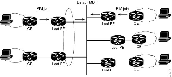
As shown in the figure, in an MLDP-based MVPN, a static default multicast distribution tree (MDT) is established for each multicast domain. The default MDT defines the path used by provider edge (PE) devices to send multicast data and control messages to every other PE device in the multicast domain. A default MDT is created in the core network using a single MP2MP LSP. The default MDT behaves like a virtual LAN.
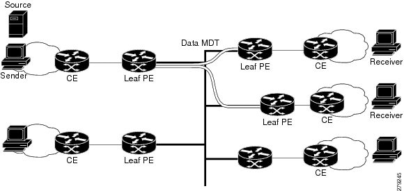
As shown in the figure, an MLDP-based MVPN also supports the dynamic creation of data MDTs for high-bandwidth transmission. For high-rate data sources, a data MDT is created using P2MP LSPs to off-load traffic from the default MDT to avoid unnecessary waste of bandwidth to PEs that did not join the stream. The creation of the data MDT is signaled dynamically using MDT Join TLV messages. Data MDTs are a feature unique to Cisco IOS software. Data MDTs are intended for high-bandwidth sources such as full-motion video inside the VPN to ensure optimal traffic forwarding in the MPLS VPN core. The threshold at which the data MDT is created can be configured on a per-device or a per-VRF basis. When the multicast transmission exceeds the defined threshold, the sending PE device creates the data MDT and sends a User Datagram Protocol (UDP) message, which contains information about the data MDT to all devices on the default MDT.
Data MDTs are created only for (S, G) multicast route entries within the VRF multicast routing table. They are not created for (*, G) entries regardless of the value of the individual source data rate.
The only transport mechanism previously available was Protocol Independent Multicast (PIM) with Multipoint Generic Routing Encapsulation (mGRE) over an IP core network. The introduction of Multicast Label Distribution Protocol (MLDP) provides transport by using MLDP with label encapsulation over an MPLS core network.
MLDP creates the MDTs as follows:
-
The default MDT uses MP2MP LSPs. - Supports low bandwidth and control traffic between VRFs.
-
The data MDT uses P2MP LSPs. - Supports a single high-bandwidth source stream from a VRF.
All other operations of MVPN remain the same regardless of the tunneling mechanism:
-
PIM neighbors in a VRF are seen across a Label Switched Path virtual interface (LSP-VIF).
-
The VPN multicast state is signaled by PIM.
The only other difference when using MLDP is that the MDT group address used in the mGRE solution is replaced with a VPN ID.
Benefits of MLDP-Based MVPN
-
Enables the use of a single MPLS forwarding plane for both unicast and multicast traffic.
-
Enables existing MPLS protection (for example, MPLS Traffic Engineering/Resource Reservation Protocol (TE/RSVP link protection) and MPLS Operations Administration and Maintenance (OAM) mechanisms to be used for multicast traffic.
-
Reduces operational complexity due to the elimination of the need for PIM in the MPLS core network.
Initial Deployment of an MLDP-Based MVPN
Initial deployment of an MLDP-based MVPN involves the configuration of a default MDT and one or more data MDTs.
A static default MDT is established for each multicast domain. The default MDT defines the path used by PE devices to send multicast data and control messages to every other PE device in the multicast domain. A default MDT is created in the core network using a single MP2MP LSP.
An MLDP-based MVPN also supports the dynamic creation of data MDTs for high-bandwidth transmission.
Default MDT Creation
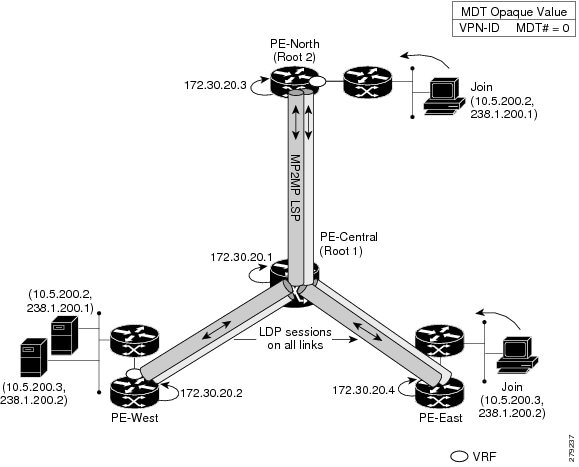
The figure shows the default MDT scenario. The Opaque value used to signal a default MDT consists of two parameters: the VPN ID and the MDT number for the VPN in the format (vpn-id, 0) where vpn-id is a manually configured 7-byte number that uniquely identifies this VPN. The default MDT is set to zero.
In this scenario, each of the three PE devices belong to the VRF called VRF and they have the same VPN ID. Each PE device with the same VPN ID will join the same MP2MP tree. The PE devices have created a primary MP2MP tree rooted at P-Central (Root 1) and a backup MP2MP tree rooted at PE-North (Root 2). There are two sources at PE-West and interested receivers at both PE-North and PE-East. PE-West will choose one of the MP2MP trees to transmit the customer VPN traffic, but all PE devices can receive traffic on either of the MP2MP trees.
LSP Downstream Default MDT Creation
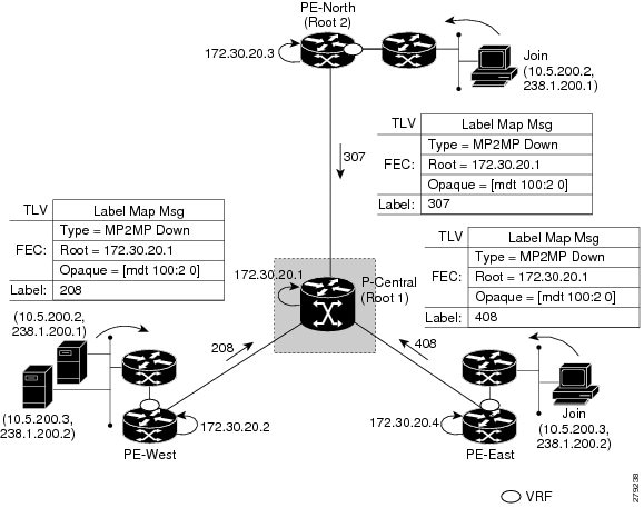
The figures show the downstream tree creation for each of the roots. Each PE device configured with VPN ID 100:2 creates the same Forwarding Equivalence Class (FEC) Type Length Value (TLV), but with a different root and downstream labels per MP2MP tree. The FEC type will be MP2MP Down, which prompts the receiving Label Switched Route (LSR) to respond with an upstream label mapping message to create the upstream path.

LSP Upstream Default MDT Creation
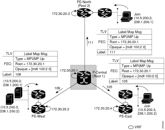
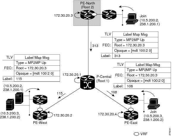
The figures show the upstream LSP creation for the default MDTs. For each downstream label received, a corresponding upstream label is sent. In the first figure, P-Central sends out three upstream labels (111, 109, and 105) to each downstream directly connected neighbor (downstream is away from the root). The process for PE-North is the same except that it only sends a single upstream label (313) as there is only one directly connected downstream neighbor, as shown in the second figure.
PIM Overlay Signaling of VPN Multicast State
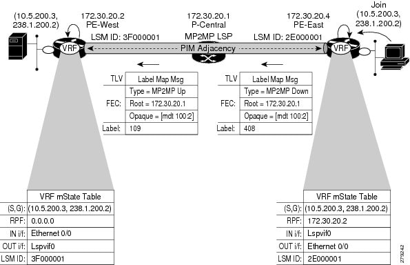
The signaling of the multicast state within a VPN is via PIM. It is called overlay signaling because the PIM session runs over the multipoint LSP and maps the VPN multicast flow to the LSP. In an MVPN, the operation of PIM is independent of the underlying tunnel technology. In the MVPN solution, a PIM adjacency is created between PE devices, and the multicast states within a VRF are populated over the PIM sessions. When using MLDP, the PIM session runs over an LSP-VIF interface. The figure shows PIM signaling running over the default MDT MP2MP LSP. Access to the MP2MP LSP is via the LSP-VIF, which can see all the leaf PE devices at the end of branches, much like a LAN interface. In the figure, PE-East sends a downstream label mapping message to the root, P-Central, which in turn sends an upstream label mapping message to PE-West. These messages result in the creation of the LSP between the two leaf PE devices. A PIM session can then be activated over the top of the LSP allowing the (S, G) states and control messages to be signaled between PE-West and PE-East. In this case, PE-East receives a Join TLV message for (10.5.200.3, 238.1.200.2) within VRF, which it inserts into the mroute table. The Join TLV message is then sent via the PIM session to PE-West (BGP next-hop of 10.5.200.3), which populates its VRF mroute table. This procedure is identical to the procedure using an mGRE tunnel.
Data MDT Scenario
In an MVPN, traffic that exceeds a certain threshold can move off the default MDT onto a data MDT.
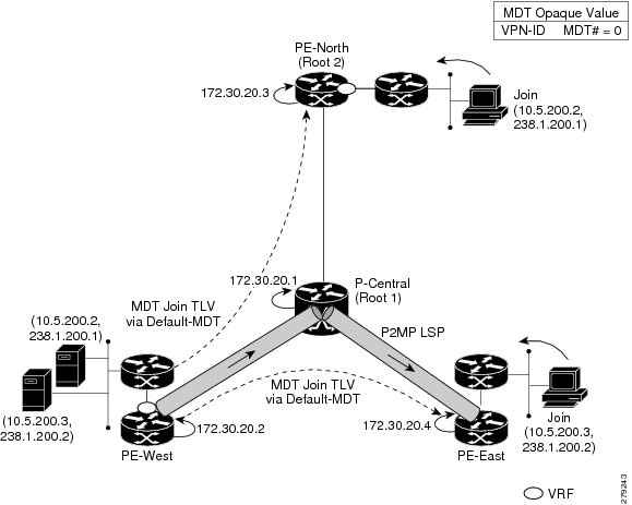
The figure shows the data MDT scenario. The Opaque value used to signal a data MDT consists of two parameters: the VPN ID and the MDT number in the format (vpn-id, MDT# > 0) where vpn-id is a manually configured 7-byte number that uniquely identifies this VPN. The second parameter is the unique data MDT number for this VPN, which is a number greater than zero.
In the scenario, two receivers at PE-North and PE-East are interested in two sources at PE-West. If the source 10.5.200.3 exceeds the threshold on the default MDT, PE-West will issue an MDT Join TLV message over the default MDT MP2MP LSP advising all PE devices that a new data MDT is being created.
Because PE-East has an interested receiver in VRF, it will build a multipoint LSP using P2MP back to PE-West, which will be the root of the tree. PE-North does not have a receiver for 10.5.200.3, therefore it will just cache the Join TLV message.
 Feedback