Installing the Cisco 4-Port and 8-Port Layer 2 Gigabit EtherSwitch Network Interface Module
August 19, 2016
This guide describes how to install the Cisco 4-Port and 8-Port Layer 2 Gigabit EtherSwitch Network Interface Module (Cisco NIM-ES2-4 and Cisco NIM-ES2-8) in the Cisco 4000 Series Integrated Services Router (ISR) and how to connect the NIM-ES2 to your network.
Contents
This guide contains the following sections:
About the Cisco 4-Port and 8-Port Layer 2 Gigabit EtherSwitch Network Interface Module
This section describes the Cisco NIM-ES2-4 and Cisco NIM-ES2-8. It contains the following sections:
Cisco NIM-ES2-4 and Cisco NIM-ES2-8 Overview
The Cisco 4-Port and 8-Port Layer 2 Gigabit EtherSwitch Network Interface Modules are switch modules to which you can connect Cisco IP phones, Cisco wireless access point workstations, and other network devices such as video devices, routers, switches, and other network components.
The following Cisco 4-Port and 8-Port Layer 2 Gigabit EtherSwitch Network Interface Modules are supported on the Cisco 4000 Series ISRs:
- 4-ports non-POE Layer 2 Gigabit Ethernet Switch Network Interface Module (NIM-ES2-4)
- 8-ports non-POE Layer 2 Gigabit Ethernet Switch Network Interface Module (NIM-ES2-8)
- 8-ports POE Layer 2 Gigabit Ethernet Switch Network Interface Module (NIM-ES2-8-P)
Multiple Cisco NIM-ES2-4 and Cisco NIM-ES2-8 units that can be present on the Cisco 4000 ISR is dictated by the total NIM slots present in the router.
 Note |
Cisco 4-Port and 8-Port Layer 2 Gigabit EtherSwitch Network Interface Modules support a maximum of 4K entries in the MAC table. |
The following table lists the maximum number of network modules supported on the router.
|
4000 Series ISR s |
SKU |
Comments |
|---|---|---|
|
4451-X |
5 |
Need SM-X-NIM-ADPTR |
|
4431 |
3 |
|
|
4351 |
5 |
Need SM-X-NIM-ADPTR |
|
4331 |
3 |
Need SM-X-NIM-ADPTR |
|
4331 |
2 |
For information about these and other features available in Cisco NIM-ES2-4 and Cisco NIM-ES2-8s, see the Cisco 4-Port and 8-Port Layer 2 Gigabit EtherSwitch Network Interface Module Configuration Guide at the following URL: hhttp://www-author.cisco.com/c/en/us/td/docs/routers/access/interfaces/NIM/software/configuration/guide/4_8PortGENIM.html/
The following modules are available with this release of the hardware:
- NIM-ES2-4—4-ports Layer 2 10/100/1000 Gigabit Ethernet Switch, Network Interface Module form single-wide factor.
- NIM-ES2-8—8-ports Layer 2 10/100/1000 Gigabit Ethernet Switch, Network Interface Module single-wide form factor.
- NIM-ES2-8-P with POE support —8-ports Layer 2 10/100/1000 Gigabit Etherne Switch, Network Interface Module single-wide form factor.
Cisco 4-Port Layer 2 Gigabit EtherSwitch Network Interface Module
The below figure shows the Cisco 4-Port Layer 2 Gigabit EtherSwitch NIM.
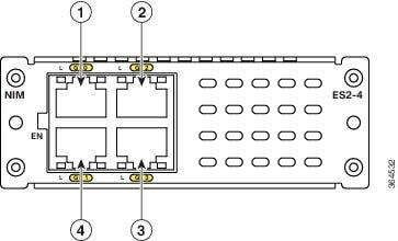
|
1 |
GE0 |
3 |
GE3 |
|
2 |
GE2 |
4 |
GE1 |
Cisco 8-Port Layer 2 non-POE Gigabit EtherSwitch Netwrok Interface Module
The below figure, show the Cisco 8-Ports Layer 2 Gigabit EtherSwitch NIM.
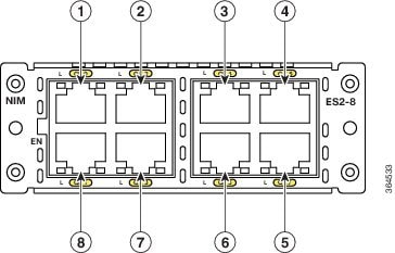
|
1 |
GE0 |
5 |
GE7 |
|
2 |
GE2 |
6 |
GE5 |
|
3 |
GE4 |
7 |
GE3 |
|
4 |
GE6 |
8 |
GE1 |
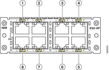
Cisco 8-Port Layer 2 Gigabit EtherSwitch Network Interface Module
The below figure, shows the Cisco 8-Port POE Layer 2 Gigabit EtherSwitch NIM.
Cisco NIM-ES2-4 and Cisco NIM-ES2-8 Ports
The following sections describe the port numbering and port types on the service modules:
Port Numbering
The Ethernet ports are numbered left to right, top to bottom. The port numbering scheme to configure the ports on the Cisco NIM-ES2-4 and Cisco NIM-ES2-8 includes the port type (such as gi or gigabitethernet for Gigabit Ethernet), and the switch port number. If you are not using the NIM-ADPTR, the slot number is always 0.
For example, to configure Gigabit Ethernet slot/subslot/port, the interface configuration command would be:
Router(config)# interface gi 0/1/0 Port Types
The following sections describe the port types on the NIM modules:
All Cisco NIM-ES2-4 and Cisco NIM-ES2-8s, use RJ-45 connectors to provide Gigabit Ethernet (GE) connections.
10/100/1000 RJ45 Ports
You can set the 10/100/1000 RJ45 ports for speed and duplex autonegotiation in compliance with IEEE 802.3ab. (The default setting is autonegotiate.)
When set for autonegotiation, the port senses the speed and duplex settings of the attached device and advertises its own capabilities. If the connected device also supports autonegotiation, the Cisco NIM-ES2-4 and Cisco NIM-ES2-8 port negotiates the best connection (that is, the fastest line speed that both devices support and full-duplex transmission if the attached device supports it) and configures itself accordingly. In all cases, the attached device must be within 100 meters (328 feet).
All 10/100/1000 RJ45 ports on the Cisco 8-Port Layer 2 Gibabit Ethernet NIM with POE can provide power to IEEE 802.3at-compliant, IEEE 802.3af-compliant, and Cisco prestandard POE device. Power over Ethernet (PoE) devices are Cisco IP phones, Cisco access points, and some Cisco switches. PoE, formerly referred to as inline power, is available only on the Cisco 8-Port Layer 2 Gibabit Ethernet NIM form factors supported by Cisco modular access routers.
The below table provides information on Cisco NIM-ES2-4 and Cisco NIM-ES2-8 port speed and duplex mode.
|
Port Function |
Explanation |
||
|---|---|---|---|
|
Speed |
The operating speed of the switch port. You can choose Auto (autonegotiation) if the connected device can negotiate the link speed with the switch port. The default settings are:
|
||
|
Duplex |
The duplex mode of the switch port. Choose from one of the following:
The default settings are:
|
Cisco NIM-ES2-4 and Cisco NIM-ES2-8 LEDs
Cisco NIM-ES2-4 and Cisco NIM-ES2-8 LEDs provide green, amber, and off states for system and port status. The following sections describe LEDs on the service modules:
Note |
Port LEDs on Cisco NIM-ES2-4 and Cisco NIM-ES2-8s only show link status. |
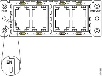
EN LED
All Cisco NIM-ES2-4 and Cisco NIM-ES2-8s have an enable (EN) LED. This LED indicates that the module has passed its self-test and is available to the router (see the below figure). The below table lists the EN LED colors and their meanings .
|
State |
System Status |
|---|---|
|
Off |
The Cisco 4-Port and 8-Port Layer 2 Gigabit EtherSwitch Network Interface Module is not powered on. |
|
Amber |
The Cisco 4-Port and 8-Port Layer 2 Gigabit EtherSwitch Network Interface Module is powered on and in booting stag. |
|
Green |
Module is in operational. |
Port LEDs
Each module has an Enable LED. The below table explains how to interpret the Enable LED status on the Cisco NIM-ES2-4 and Cisco NIM-ES2-8s.
|
Enable LED Color |
Description |
|---|---|
|
Off |
Module is not powered on. |
|
Amber |
Module is powered on and in booting state |
|
Green |
Module completes booting and in working state. |
Port Link/Act LED
Each port has a Link LED. The below table explains how to interpret the Port Link/Act LED status on the Cisco NIM-ES2-4 and Cisco NIM-ES2-8s.
|
Port Link /Act LED |
Description |
|---|---|
|
Off |
Link is down. |
|
Green |
Link is up. |
|
Flashing Green |
Activity is occurring. The port is transmitting or receiving data. |
PoE LED Status
For the PoE module, each port also has a PoE LED. The below table explains how to interpret the PoE LED status on the Cisco 8-Port Layer 2 Gigabit Ethernet NIMs.
|
PoE LED |
Description |
|---|---|
|
Off |
Inline power is Off. |
|
Green |
Inline power is On. |
Preparing for Installation
The following sections describe safety warnings, general maintenance guidelines, and safety recommendations that you must read before installing and using the NIM:
Safety Warnings
DANGER |
Read the installation instructions before connecting the system to the power source. Statement 1004 |
DANGER |
Only trained and qualified personnel should be allowed to install, replace, or service this equipment. Statement 1030 |
DANGER |
This equipment must be installed and maintained by service personnel as defined by AS/NZS 3260. Incorrectly connecting this equipment to a general-purpose outlet could be hazardous. The telecommunications lines must be disconnected 1) before unplugging the main power connector or 2) while the housing is open, or both. Statement 1043 |
DANGER |
Before working on a system that has an on/off switch, turn OFF the power and unplug the power cord. Statement 1 |
DANGER |
This unit might have more than one power supply connection. All connections must be removed to de-energize the unit. Statement 1028 |
DANGER |
This equipment must be grounded. Never defeat the ground conductor or operate the equipment in the absence of a suitably installed ground conductor. Contact the appropriate electrical inspection authority or an electrician if you are uncertain that suitable grounding is available. Statement 1024 |
DANGER |
Hazardous network voltages are present in WAN ports regardless of whether power to the unit is OFF or ON. To avoid electric shock, use caution when working near WAN ports. When detaching cables, detach the end away from the unit first. Statement 1026 |
DANGER |
Before opening the unit, disconnect the telephone-network cables to avoid contact with telephone-network voltages. Statement 1041 |
DANGER |
Before working on equipment that is connected to power lines, remove jewelry (including rings, necklaces, and watches). Metal objects will heat up when connected to power and ground and can cause serious burns or weld the metal object to the terminals. Statement 43 |
DANGER |
Do not use this product near water; for example, near a bath tub, wash bowl, kitchen sink or laundry tub, in a wet basement, or near a swimming pool. Statement 1035 |
DANGER |
Never install telephone jacks in wet locations unless the jack is specifically designed for wet locations. Statement 1036 |
DANGER |
Never touch uninsulated telephone wires or terminals unless the telephone line has been disconnected at the network interface. Statement 1037 |
DANGER |
Avoid using a telephone (other than a cordless type) during an electrical storm. There may be a remote risk of electric shock from lightning. Statement 1038 |
DANGER |
To report a gas leak, do not use a telephone in the vicinity of the leak. Statement 1039 |
DANGER |
There is the danger of explosion if the battery is replaced incorrectly. Replace the battery only with the same or equivalent type recommended by the manufacturer. Dispose of used batteries according to the manufacturer's instructions. Statement 1015 |
DANGER |
Blank faceplates and cover panels serve three important functions: they prevent exposure to hazardous voltages and currents inside the chassis; they contain electromagnetic interference (EMI) that might disrupt other equipment; and they direct the flow of cooling air through the chassis. Do not operate the system unless all cards, faceplates, front covers, and rear covers are in place. Statement 1029 |
DANGER |
No user-serviceable parts inside. Do not open. Statement 1073 |
DANGER |
For connections outside the building where the equipment is installed, the following ports must be connected through an approved network termination unit with integral circuit protection. Statement 1044 |
Preventing Electrostatic Discharge Damage
Electrostatic discharge can damage equipment and electrical circuitry. Electrostatic discharge occurs when electronic printed circuit cards, such as those used in Cisco service modules are improperly handled and can result in complete or intermittent equipment failure. Always observe the following procedures to prevent electrostatic discharge damage (ESD) when installing, removing, and replacing any electronic printed circuit cards:
- Make sure that the router chassis is electrically connected to earth ground.
- Wear an ESD-preventive wrist strap, and make sure that it makes good contact with your skin.
- Connect the wrist strap clip to an unpainted portion of the chassis frame to channel unwanted ESD voltages to ground.
- The wrist strap and clip must be used correctly to ensure proper ESD protection. Periodically confirm that the resistance value of the ESD-preventive wrist strap is between 1 and 10 megohms (Mohm).
- If no wrist strap is available, ground yourself by touching the metal part of the router chassis.
General Maintenance Guidelines and Safety Recommendations for Cisco NIM-ES2-4 and Cisco NIM-ES2-8s
General Maintenance Guidelines
- Keep the router chassis area clear and dust-free during and after installation.
- If you remove the chassis cover for any reason, store it in a safe place.
- Do not perform any action that creates a hazard to people or makes equipment unsafe.
- Keep walk areas clear to prevent falls or damage to equipment.
- Follow installation and maintenance procedures as documented by Cisco Systems, Inc.
- Always wear an electrostatic discharge (ESD)-preventive wrist strap and ensure that it makes good contact with your skin when you remove or install an Network Interface Module (NIM). Connect the equipment end of the wrist strap to the metal part of the chassis.
- Handle the NIMs by the edges only. NIMs are ESD-sensitive components and can be damaged by mishandling.
Safety Recommendations
To prevent hazardous conditions, follow these safety recommendations while working with this equipment:
- Keep tools away from walk areas where you or others could fall over them.
- Do not wear loose clothing around the router. Fasten your tie or scarf and roll up your sleeves to prevent clothing from being caught in the chassis.
- Wear safety glasses when working under any conditions that might be hazardous to your eyes.
- Locate the emergency power-off switch in the room before you start working. If an electrical accident occurs, shut the power off.
- Before working on the router, turn off the power and unplug the power cord.
-
Disconnect all power sources before doing the following:
- Installing or removing a router chassis
- Working near power supplies
- Do not work alone if potentially hazardous conditions exist.
- Always check that power is disconnected from a circuit.
- Remove possible hazards from your work area, such as damp floors, ungrounded power extension cables, or missing safety grounds.
-
If an electrical accident occurs, proceed as follows:
- Use caution; do not become a victim yourself.
- Turn off power to the room using the emergency power-off switch.
- Determine the condition of the victim and send another person to get medical aid or call for help.
- Determine if the person needs rescue breathing or external cardiac compressions; then take appropriate action.
Installing and Removing the Cisco 4-Port and 8-Port Layer 2 NIM in a Cisco 4000 Series ISR
This section describes the following tasks for the Cisco NIM-ES2-4 and Cisco NIM-ES2-8:
 Caution |
Always wear an electrostatic discharge (ESD)-preventive wrist strap and ensure that it makes good contact with your skin when you install or remove an Cisco NIM-ES2-4 and Cisco NIM-ES2-8. Connect the equipment end of the wrist strap to the metal part of the chassis. |
Caution |
Handle your NIMs by the edges only. NIMs are ESD-sensitive components and can be damaged by mishandling. |
Software Requirements for the Cisco NIM-ES2-4 and Cisco NIM-ES2-8-P
Cisco IOS XE Release 3.15S, Cisco IOS 15.5(2)S, and Cisco IOS XE Release 16.3.1 or a later release is required to install the Cisco NIM-ES2-4 and Cisco NIM-ES2-8-P.
To determine the version of Cisco IOS software that is running on your router, log in to the router and enter the show version command:
Router> show version
Cisco IOS XE Software, Version 03.15.00.S - Standard Support Release
Cisco IOS Software, ISR Software (X86_64_LINUX_IOSD-UNIVERSALK9-M), Version 15.5(2)S, RELEASE SOFTWARE (fc3)
Technical Support: http://www.cisco.com/techsupport
Copyright (c) 1986-2015 by Cisco Systems, Inc.
Compiled Sun 22-Mar-15 02:32 by mcpre
Installing the Cisco NIM-ES2-4 and Cisco NIM-ES2-8 in a Cisco 4000 Series ISR
Use the following procedure to install the Cisco NIM-ES2-4 and Cisco NIM-ES2-8 on your router:
SUMMARY STEPS
- Read the Safety Warnings before you perform any module replacement.
- Remove the blank faceplates installed over the slot you intend to use.
- Push the Cisco NIM-ES2-4 and Cisco NIM-ES2-8 into place until you feel the edge connector seat securely into the connector on the router backplane. The module faceplate should contact the chassis rear panel.
- Using a number 1 Phillips or flat-blade screwdriver, tighten the captive mounting screws on the module faceplate.
DETAILED STEPS
| Step 1 |
Read the Safety Warnings before you perform any module replacement. |
| Step 2 |
Remove the blank faceplates installed over the slot you intend to use. |
| Step 3 |
Push the Cisco NIM-ES2-4 and Cisco NIM-ES2-8 into place until you feel the edge connector seat securely into the connector on the router backplane. The module faceplate should contact the chassis rear panel. |
| Step 4 |
Using a number 1 Phillips or flat-blade screwdriver, tighten the captive mounting screws on the module faceplate. |
Removing the Cisco NIM-ES2-4 and Cisco NIM-ES2-8 from a Cisco 4000 Series ISR
Use the following procedure to remove the Cisco NIM-ES2-4 and Cisco NIM-ES2-8 from your router:
SUMMARY STEPS
- Read the Safety Warnings before you perform any module replacement.
- Locate the Cisco NIM-ES2-4 and Cisco NIM-ES2-8 to be removed.
- Using a number 1 Phillips or flat-blade screwdriver, unscrew the captive mounting screws on the module faceplate.
- Pull the Cisco NIM-ES2-4 and Cisco NIM-ES2-8 out of the chassis.
- Place the NIM in an antistatic bag to protect it from electrostatic discharge (ESD) damage.
DETAILED STEPS
| Step 1 |
Read the Safety Warnings before you perform any module replacement. |
| Step 2 |
Locate the Cisco NIM-ES2-4 and Cisco NIM-ES2-8 to be removed. |
| Step 3 |
Using a number 1 Phillips or flat-blade screwdriver, unscrew the captive mounting screws on the module faceplate. |
| Step 4 |
Pull the Cisco NIM-ES2-4 and Cisco NIM-ES2-8 out of the chassis. |
| Step 5 |
Place the NIM in an antistatic bag to protect it from electrostatic discharge (ESD) damage. |
Verifying Cisco Cisco NIM-ES2-4 and Cisco NIM-ES2-8 Installation on a Cisco 4000 Series ISR
Use the show diag command to verify that the Cisco NIM-ES2-4 and Cisco NIM-ES2-8 has been installed correctly. The following example displays one NIM installed and recognized by the system.
Router# show diag subslot 0/1/eeprom
SPA EEPROM data for subslot 0/1:
Product Identifier (PID) : NIM-ES2-8
Version Identifier (VID) : V01
PCB Serial Number : FOC18520K6J
Hardware Revision : 1.0
CLEI Code : IPU3BB3CAACisco IOS XE Software, Version 03.15.00.S - Standard Support ReleasePower Specifications for the Cisco NIM-ES2-4 and Cisco NIM-ES2-8s
The Cisco NIM-ES2-4 and Cisco NIM-ES2-8s supports inline power on IP phones with –30 V power. This allows IP phones to be plugged into a standard RJ-45 jack and be powered from the switch rather than from an AC wall outlet.
The Cisco NIM-ES2-4 and Cisco NIM-ES2-8 distributes the –30 V power to each of the Ethernet ports that are configured for PoE. Each port can be independently configured for PoE.
DANGER |
Voltages that present a shock hazard may exist on Power over Ethernet (PoE) circuits if interconnections are made using uninsulated exposed metal contacts, conductors, or terminals. Avoid using such interconnection methods, unless the exposed metal parts are located within a restricted access location and users and service people who are authorized within the restricted access location are made aware of the hazard. A restricted access area can be accessed only through the use of a special tool, lock and key or other means of security. Statement 1072 |
Connecting to the Cisco NIM-ES2-4 and Cisco NIM-ES2-8 Ports
Both FE and GE ports are used to connect PCs or workstations to the network.
A 10/100/1000 Gigabit Ethernet (GE) port can be used as an uplink port to connect to another router or a server, or the GE port can trunk to another Cisco NIM-ES2-4 and Cisco NIM-ES2-8 or switch located in the same chassis or in a separate installation.
Note |
Connecting a GE port to the network requires a Category 5 cable with RJ-45 male connectors, not provided with the switch module. Category 5 cables are widely available. |
DANGER |
To comply with the Telcordia GR-1089 NEBS standard for electromagnetic compatibility and safety, connect the Cisco NIM-ES2-4 and Cisco NIM-ES2-8 only to intra-building or unexposed wiring or cable. The intra-building port(s) of the equipment or subassembly must not be metallically connected to interfaces that connect to the OSP or its wiring. These interfaces are designed for use as intra-building interfaces only (Type 2 or Type 4 ports as described in GR-1089-CORE, Issue 4) and require isolation from the exposed OSP cabling. The addition of Primary Protectors is not sufficient protection in order to connect these interfaces metallically to OSP wiring. The intra-building cable must be shielded and the shield must be grounded at both ends. |
Related Documents
|
Related Topic |
Document Title |
|---|---|
|
Configuration guide for the Cisco NIM-ES2-4 and Cisco NIM-ES2-8 |
|
|
Hardware installation instructions for service modules |
Hardware Installation Guide for the Cisco 4000 Series Integrated Services Router |
|
General information about configuration and the command reference. |
Software Configuration Guide for the Cisco 4000 Seris Integrated Services Router |
|
Regulatory compliance information for the Cisco 4000 Series ISR. |
Regulatory Compliance and Safety Information for the Cisco 4000 Series Integrated Services Router |
 Feedback