Introduction to this Document
This Release Notes document provides information about the Cisco Catalyst IR1101 Rugged Series Routers, Cisco Catalyst IR1800 Rugged Series Routers, Cisco Catalyst IR8140 Heavy Duty Series Routers,and Cisco Catalyst IR8340 Rugged Series Routers running Cisco IOS XE 17.13.1a.
 Note |
Beginning with this release, the Cisco ESR6300 Embedded Series Router release notes are a separate document. Release Notes for Cisco ESR 6300 Router |
This document describes the new features, limitations, troubleshooting, besides providing recommended configurations, caveats, and information on how to obtain support and documentation.
Note |
The documentation set for this product strives to use bias-free language. For purposes of this documentation set, bias-free is defined as language that does not imply discrimination based on age, disability, gender, racial identity, ethnic identity, sexual orientation, socioeconomic status, and intersectionality. Exceptions may be present in the documentation due to language that is hardcoded in the user interfaces of the product software, language used based on RFP documentation, or language that is used by a referenced third-party product. |
Cisco Catalyst IR1101 Rugged Series Router
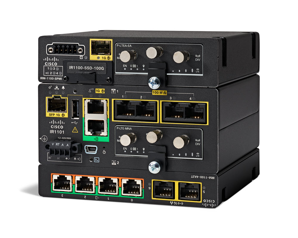
The Cisco Catalyst IR1101 Rugged Series Router is a next-generation modular industrial router, which has a base platform with additional pluggable modules that can be added. The pluggable modules provide the flexibility of adding different interfaces to the IR1101 platform, for example, a cellular module, which provides 5G and Fourth-Generation Long-Term Evolution (4G LTE) cellular networks.
The IR1101 also has expansion modules that adds key capabilities to the IR1101. The expansion modules are:
|
SKU ID |
Description |
|---|---|
|
IRM-1100-SPMI |
Expansion Module with 1 GE SFP, 1 Pluggable Module, 4 GPIO ports on 1 Digital I/O Connector, and 1 mSATA SSD Slot. |
|
IRM-1100-SP |
Expansion Module with 1 GE SFP and1 Pluggable Module. |
|
IRM-1100-4A2T |
Expansion Module with an additional four asynchronous serial ports and two Ethernet RJ45 LAN interfaces. |
|
Cellular pluggable modules |
A number of pluggable modules are available for cellular connectivity. |
|
IRM-SSD-100G |
100 GB pluggable industrial SSD. |
|
P-LPWA-800 P-LPWA-900 |
Cisco LoRaWAN Pluggable Interface Module designed for RF regional profile US915, AS923 and AU915. Cisco LoRaWAN Pluggable Interface Module designed for the EU868, IND865 and RU864 RF regional profile. |
|
P-LTE-450 |
Cisco 450MHz Category-4 LTE Pluggable Interface Module. |
Cisco Catalyst IR1800 Rugged Series Router
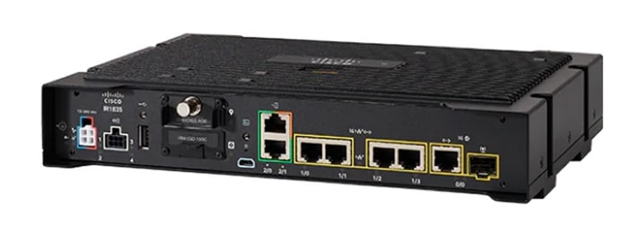
The Cisco Catalyst IR1800 Rugged Series Router is a modular industrial router. The IR1800 series has four base platforms with additional pluggable modules that can be added. The pluggable modules provide the flexibility of adding different interfaces to the base platform.
The IR1800 series consists of four base platforms:
-
IR1821
-
IR1831
-
IR1833
-
IR1835
The IR1800 series features a base platform with modularity, which includes:
|
SKU ID |
Description |
|---|---|
|
IRM-GNSS-ADR |
GPS Module with Automotive Dead Reckoning. |
|
WP-WIFI6-x |
Wi-Fi 6 Network Interface Module (NIM). |
|
Cellular pluggable modules |
A number of pluggable modules are available for cellular connectivity. |
|
IRM-SSD-100G |
100 GB pluggable industrial SSD. |
|
Feature |
IR1821 |
IR1831 |
IR1833 |
IR1835 |
|---|---|---|---|---|
|
Processor Frequency |
600 MHz |
600 MHz |
600 MHz |
1200 MHz |
|
DDR Memory |
4 GB |
4 GB |
4 GB |
8 GB |
|
Flash Storage |
4 GB |
4 GB |
4 GB |
8 GB |
|
PIM Slot |
1 |
2 |
2 |
2 |
|
Wi-Fi-6 NIM Module Slot |
1 |
1 |
1 |
1 |
|
PoE |
No |
No |
Yes |
Yes |
|
SSD Module Slot |
No |
No |
Yes |
Yes |
|
GPS FRU Module Slot |
No |
No |
Yes |
Yes |
|
Digital I/O |
No |
No |
No |
Yes |
|
Asynchronous Serial Interface |
(1) RS232 DTE |
(1) RS232 DTE (1) RS232 DCE |
(1) RS232 DTE (1) RS232 DCE |
(1) RS232 DTE (1) RS232 DCE/RS485 |
Cisco Catalyst IR8140 Heavy Duty Series Router
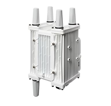
The Cisco Catalyst IR8140 Heavy Duty Series Router (IR8140H), is a next-generation modular IP67 Industrial Router for outdoor use.
These are the two IR8140H models:
-
IR8140H-P-K9 (with PoE PSE)
-
IR8140H-K9 (without PoE PSE)
The IR8140H series features contains four external module slots plus two onboard WAN ports, and supports the following:
-
60-W PSU
-
CPU 1.2 GHz
-
8GB RAM
-
8GB Flash Storage
-
GPS onboard receiver
-
900-MHz WPAN – OFDM/FSK Module
-
mSATA module
-
1x 1-Gigabit Ethernet SFP WAN
-
1x 1-Gigabit Ethernet Cu WAN
-
PoE (15 W) supported only in the IR8140H-P-K9 PID
-
12VDC_OUT port (only available when PoE is not in use)
-
Battery Backup Units (BBUs): Up to three
-
2x Alarm ports (Digital I/O)
-
IRMH modules for CAT 4 LTE, CAT 6 LTE, CAT 18 LTE, and 5G
Cisco Catalyst IR8340 Rugged Series Router
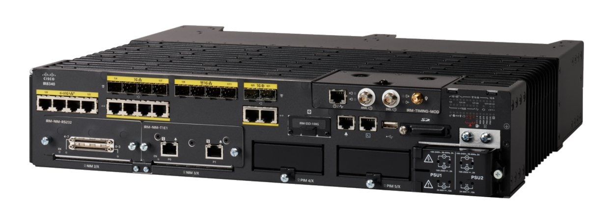
The Cisco Catalyst IR8340 Rugged Series Router, is the first all-in-one industrial-grade, integrated routing, switching, and security platform.
The IR8340 router features two Pluggable Interface Module (PIM) slots, two single-wide IRM-NIM slots, plus 12 onboard LAN ports, and two WAN ports, and supports the following:
-
150W or 250W PSU, low-voltage DC and high-voltage AC/DC options
-
PTP on LAN ports - Default, power and Dot1as profiles
-
Dual slots for 5G and 4G LTE PIM
-
T1/E1 Network Interface Modules (NIM)
-
8-port Asynchronous/Synchronous Network Interface Module (NIM) IRM-NIM-RS232
-
mSATA module
-
2 x 1-G Combo WAN ports
-
4 x 1-G Copper LAN ports
-
4 x 1-G Combo LAN ports
-
4 x 1-G SFP LAN ports
-
PoE PoE+ UPoE (up to 60 W) support on LAN ports 1-4
-
2 x IN and 1 x OUT Alarm ports (RJ45)
Interface Naming Conventions
Cisco Catalyst IR1101 Rugged Series Router
The following section shows the names of the interfaces on each of the IoT routers.
| Port |
Naming Convention |
|---|---|
|
Gigabit Ethernet combo port |
GigabitEthernet0/0/0 |
|
Gigabit Ethernet SFP port on IRM-1100 |
GigabitEthernet0/0/5 |
|
Gigabit Ethernet on IRM-1100-4A2T mounted on the Expansion side |
gigabitetherenet 0/0/5 gigabitetherenet 0/0/6 |
|
Fast Ethernet ports |
FastEthernet0/0/1 FastEthernet0/0/2 FastEthernet0/0/3 FastEthernet0/0/4 |
|
Cellular Interface on IR1101 Base |
Cellular 0/1/0 Cellular 0/1/1 |
|
Cellular Interface on IRM-1100 mounted on the top (EM) side |
Cellular 0/3/0 Cellular 0/3/1 |
|
Cellular Interface on IRM-1100 mounted on the bottom (CM) side |
Cellular 0/4/0 Cellular 0/4/1 |
|
Asynchronous Serial Interface Base |
Async0/2/0 |
|
IRM-1100-4A2T is mounted on the top (EM) side |
async 0/3/0 async 0/3/1 async 0/3/2 async 0/3/3 |
|
IRM-1100-4A2T is mounted on the bottom (CM) side |
async 0/4/0 async 0/4/1 async 0/4/2 async 0/4/3 |
|
USB |
usbflash0: |
|
mSATA |
msata |
|
IR1101 Base Unit Alarm input |
alarm contact 0 |
|
GPIO on IRM-1100 |
alarm contact 1-4 |
|
LoRaWAN interface on IR1101 Base |
LORAWAN0/1/0 |
|
LoRaWAN interface on the top (EM) side |
LORAWAN0/3/0 |
|
Gigabit Ethernet interface for LTE 450MHz module on IR1101 Base |
GI0/1/0 GI0/1/0.x for multiPDN operation |
|
Gigabit Ethernet interface for LTE 450MHz module mounted on the bottom (CM) side |
GI0/4/0 |
Cisco Catalyst IR1800 Rugged Series Router
| Port |
Naming Convention |
|---|---|
|
Gigabit Ethernet combo port |
GigabitEthernet0/0/0 |
|
Gigabit Ethernet ports |
GigabitEthernet0/1/0 GigabitEthernet0/1/1 GigabitEthernet0/1/2 GigabitEthernet0/1/3 |
|
Cellular Interface |
Cellular 0/4/0 Cellular 0/4/1 Cellular 0/5/0 Cellular 0/5/1 |
|
Asynchronous Serial Interface |
Async0/2/0 Async0/2/1 (when the base platform supports two asynchronous serial interfaces) |
|
Wi-Fi Interface |
Wl0/1/4 |
|
USB |
usbflash0: |
|
mSATA |
msata |
|
GPIO |
alarm contact 1-4 |
Cisco Catalyst IR8140 Heavy Duty Series Router
| Port |
Naming Convention |
|---|---|
|
Gigabit Ethernet ports |
GigabitEthernet0/0/0 GigabitEthernet0/0/1 |
|
Cellular Interface |
Cellular 0/2/0 OR Cellular 0/3/0 |
|
SSD |
Virtual port Group0 |
|
WPAN |
Wpan 0/1/0 Wpan 0/2/0 Wpan 0/3/0 |
|
Digital IO |
alarm contact 1-2 |
Cisco Catalyst IR8340 Rugged Series Router
| Port |
Naming Convention |
|---|---|
|
Gigabit Ethernet WAN ports |
GigabitEthernet0/0/0 GigabitEthernet0/0/1 |
|
Gigabit Ethernet LAN ports |
GigabitEthernet0/1/0 GigabitEthernet0/1/1 GigabitEthernet0/1/2 GigabitEthernet0/1/3 GigabitEthernet0/1/4 GigabitEthernet0/1/5 GigabitEthernet0/1/6 GigabitEthernet0/1/7 GigabitEthernet0/1/8 GigabitEthernet0/1/9 GigabitEthernet0/1/10 GigabitEthernet0/1/11 |
|
Cellular Interface |
Cellular 0/4/0 Cellular 0/4/1 Cellular 0/5/0 Cellular 0/5/1 |
|
NIM Interface (Asynchronous/Synchronous Serial Ports or E1/T1 ports) |
0/2/0 0/2/1 0/3/0 0/3/1 |
|
mSATA SSD |
msata |
|
GPIO |
alarm contact 1-2 |
|
USB Port |
usb0: |
|
Console Port |
Line console 0 |
Software Images for Cisco IOS XE Release 17.13.1a
Note |
You must have a Cisco.com account to download the software. |
Cisco IOS XE Release 17.13.1a includes the following Cisco images.
|
Router |
Image Type |
Filename |
|---|---|---|
|
IR1101 |
Universal |
ir1101-universalk9.17.13.1a.SPA.bin |
|
NPE |
ir1101-universal9_npe.17.13.1a.SPA.bin |
|
|
IR1800 |
Universal |
IR1800-universalk9.17.13.1a.SPA.bin |
|
NPE |
IR1800-universal9_npe.17.13.1a.SPA.bin |
|
|
IR8140 |
Universal |
IR8100-universalk9.17.13.1a.SPA.bin |
|
NPE |
IR8100-universal9_npe.17.13.1a.SPA.bin |
|
|
IR8340 |
Universal |
IR8340-universalk9.17.13.1a.SPA.bin |
|
NPE |
IR8340-universalk9_npe.17.13.1a.SPA.bin |
The latest software downloads for the routers can be found at:
https://software.cisco.com/download/home/286323433
Click the link corresponding to your device to take you to the specific software you are looking for.
Cellular Module Modem Firmware, OEM/PRI for Cisco IoT Polaris Platforms
This section contains the latest modem firmware available for each of the modems used by the Cisco IoT Industrial routers.
Note |
Cisco IOS XE updates do not automatically update the modem firmware. The user should check and update to the latest firmware. See the following table for the latest information: |
See the Cisco Firmware Upgrade Guide for 4G LTE and 5G Cellular Modems for upgrade instructions.
|
Cellular Module |
Modem |
Firmware Version |
Software Download Link |
|---|---|---|---|
|
P-5GS6-GL |
FN980 |
38.03.0202 |
https://software.cisco.com/download/home/286329300/type/284285628/release/38.03.0202 |
|
P-LTEA7-NA |
EM7411 |
01.14.22.00 |
|
|
P-LTEA7-EAL |
EM7421 |
01.14.22.00 |
|
|
P-LTEA7-JP |
EM7431 |
01.14.22.00 |
|
|
P-LTEAP18-GL IRMH-LTEAP18-GL |
LM960 |
32.00.1x7 |
|
|
P-LTE-450 |
IPS-701 |
— |
Firmware upgrades are only available through the manufacturer Intelliport. See the 450MHz Category-4 LTE PIM chapter of the Cellular Pluggable Interface Module Configuration Guide. |
|
P-LTEA-EA IRMH-LTEA-EA |
EM7455 |
02.32.11.00 |
|
|
P-LTEA-LA IRMH-LTEA-LA |
EM7430 |
02.33.03.00 |
|
|
P-LTE-VZW |
WP7601 |
02.37.0x.00 |
|
|
P-LTE-US |
WP7603 |
02.37.0x.00 |
|
|
P-LTE-JN |
WP7605 |
02.28.03 |
|
|
P-LTE-GB |
WP7607 |
02.37.03.05 |
|
|
P-LTE-IN |
WP7608 |
02.28.03 |
|
|
P-LTE-AU |
WP7609 |
02.28.03 |
|
|
P-LTE-MNA |
WP7610 |
02.37.0x.00 |
New Features in Cisco IOS XE 17.13.1a
The following sections describe the major enhancements available in Cisco IOS XE 17.13.1a on each of the routers.
Major Enhancements in IR1101
This section describes the new features for the IR1101.
Also see the Major Enhancements Common to all IoT Routers.
IOx Access to USB Storage
Customers have requested the ability to mount the host a USB thumb drive within the Docker container running on IOx. The bootflash has a limited number of read/write cycles, and a container continuously writing on the eMMC would prematurely wear out the unit. Using the USB thumb drive will allow Docker containers to write in a continuous manner without compromising the integrity of the bootflash.
Feature Requirements and Limitations
The following apply to this feature:
-
The filesystem types supported for USB thumb drives on the IR1101 are: VFAT, EXT2 and EXT3. However, IOx only supports mounting of USB thumb drives with EXT2 and EXT3 filesystem. Cisco recommends EXT3 for the following reasons:
-
EXT3 is a journaling filesystem, which means there are not fragmentation issues.
-
Read/Writes are significantly faster with EXT3 filesystems
-
VFAT has a 4 GB maximum file-size limitation, which is a problem with container continuously writing large files.
-
-
If the USB thumb drive is removed while a write operation by IOx apps is in progress, all the files included in the copy operation will be lost.
-
If the USB thumb drive is removed while IOX and the app are using it, IOX will still be in running state. The functionality of the app using USB thumb drive as storage will be severely impacted, since it will not be able to read and/or write on the USB thumb drive.
Making the USB Thumb Drive Available to the IOx App
In order to make the USB thumb drive available to the IOx app, you need to issue a run option. See the following example:
Router(config-app-hosting-docker)#run-opts 1 "-v /mnt/usb0:/usbflash0"This command will mount the USB thumb drive file system within the IOx application filesystem, and it will be available in the /usbflash0 folder, as showed by the following log from an IOx application:
/ # ls -al usbflash0/
total 705424
drwxrwxrwx    4 root     root          4096 Nov 10 22:42 .
drwxr-xr-x    1 root     root          4096 Nov 15 17:22 ..
-rw-r--r--    1 65534    65534    720025859 Nov 10 22:46 ir1101-universalk9.SSA.bin
drwx------    2 65534    65534        16384 Nov  8 16:32 lost+found
#
P-LTE-450 Support on Autonomous Mode
This release introduces two modes of setting the required credentials to communicate with the module. The username and password that should be used in these CLIs can be found on the sticker label that comes with the P-LTE-450 module.
Important |
You MUST set the username and password before performing any P-LTE-450 parameter configuration. |
Configuration
The recommended configuration is through the Config mode:
interface GigabitEthernet 0/1/0
lte450 credential username username password password
Using the Exec mode:
hw-module subslot 0/1 lte450 set-info username username password password [encrypt]Note |
Execution of this command will create a file called bootflash:lte450.info and should not be deleted. |
P-LTE-450 Support Over SDWAN/vManage
The P-LTE-450 is a 450MHz Category-4 LTE PIM, which addresses LTE use cases primarily targeting utility, public safety, and critical infrastructure maintained by public organizations in Europe and other world regions. The module supports only Band 31 and 72 for LTE 450MHz networks.
Support for the P-LTE-450 was introduced in IOS XE 17.12.1a. This release introduces support for the P-LTE-450 over SDWAN /vManage.
Guidelines and Limitations
The following are the limitations of the P-LTE-450 with SDWAN/vManage:
-
No PNP support on P-LTE-450 as a primary link.
-
P-LTE-450 parameter configuration is only supported with CLI templates.
-
P-LTE-450 credential configuration via vManage is not supported on this release. Will be supported in the vManage 20.16 release.
Additional Documentation
Additional documentation for SDWAN/vManage is available at the following links:
Major Enhancements in IR1800
This section describes the new features for the IR1800.
Also see the Major Enhancements Common to all IoT Routers.
Change in Vendor for GNSS Module
This feature applies to the IR1833 and IR1835 only. There was a change in chip manufacturers on the IRM-GNSS-ADR pluggable module. There have been no changes in functionality, however you will see a change in the display of vendor information and firmware version.
See the following example:
Router#show platform hardware gps dead-reckoning
DR Vehicle interface mode: OBDDII
GPS/DR Vendor Info: VIC3DA
GPS/DR module FW Version: 4.6.18.11
DR Calibration Status:
DR is not calibrated
Odometer is not calibrated
Gain is not calibrated
Offset is not calibrated

CAN Bus Status:
CAN Bus Tx Count: 11
CAN Bus Tx error Count: 150930
IOX Access to IR1800 On-board Accelerometer and Gyroscope
This feature allows on-board accelerometer and gyroscope sensor data to be streamed to IOX via a TTY. This feature is disabled by default, and will keep feature parity with IR829 accelerometer and gyroscope sensor data feature. The CLIs for this feature are defined below.
Configuration Commands
The following commands are available:
Router(config)#acc-gyro ?
  enable     Enable
  frequency  Frequency in reading
Router(config)#acc-gyro freq ?
  four/sec  Reading 4 times per second
  one/min   Reading 1 times per minute
  one/sec   Reading 1 time per second (default value)
  ten/min   Reading 10 times per minute
Show Commands
The following command is available:
Router# show platform hardware acc-gyro sensor-data

Date                Time   G-X     G-Y     G-Z    XL-X    XL-Y   XL-Z
2022:10:26:16:58:13.855143 1137.50 -297.50 621.25 -18.056 -3.111 -966.057
2022:10:26:16:58:14.863668 1058.75 -122.50 735.00 -17.629 -2.989 -965.996
2022:10:26:16:58:15.869117 1207.50 -140.00 726.25 -18.361 -3.294 -965.813
2022:10:26:16:58:16.874036 1268.75 -192.50 717.50 -18.178 -3.050 -965.874
2022:10:26:16:58:17.884764 1163.75 -420.00 717.50 -18.056 -2.989 -965.813
2022:10:26:16:58:18.894063 1347.50 -148.75 708.75 -18.117 -3.477 -965.935
2022:10:26:16:58:19.900830 1137.50 -315.00 577.50 -18.239 -3.599 -965.935
2022:10:26:16:58:20.908765 1137.50 -131.25 726.25 -17.873 -3.538 -965.813
2022:10:26:16:58:21.916674 1137.50 -262.50 726.25 -18.361 -2.867 -965.935
2022:10:26:16:58:22.927371 1137.50 -323.75 516.25 -17.934 -3.477 -965.569
2022:10:26:16:58:23.934275 1120.00 -647.50 516.25 -18.361 -3.416 -965.752
2022:10:26:16:58:24.940819 1111.25 -262.50 743.75 -18.422 -2.989 -965.386
2022:10:26:16:58:25.947471 1190.00 -201.25 673.75 -17.995 -3.416 -966.057
2022:10:26:16:58:26.953120 1093.75 -288.75 577.50 -17.995 -3.233 -965.874
2022:10:26:16:58:27.961469 1137.50 -428.75 551.25 -18.117 -2.745 -965.996
2022:10:26:16:58:28.971354 1050.00 -271.25 717.50 -18.361 -3.233 -965.508
2022:10:26:16:58:29.981967 1172.50 78.75 840.00 -18.117 -3.538 -965.386
Other
The existing debug hardware acc-gyro sensor-data command has been enhanced to provide additional debug messages for better serviceability. The debug messages will cover the following:
-
How frequent the sensor data are pushed from the module to IOS, it must at least once per second.
-
The latest sensor data received from the module.
Unified Threat Defense (UTD)
Unified Threat Defense (UTD) is Cisco's premier network security solution which provides a comprehensive suite of security features, such as:
-
Enterprise Firewall
-
IPS/IDS
-
Advanced Malware Protection
-
URL Filtering
-
DNS Security
UTD is available on the IR1835 router.
IR1835 Limitations
The following are product specific limitations:
-
UTD container requires a minimum space of 1.8 GB.
-
UTD is supported in both Autonomous mode and Controller Mode, but in Autonomous mode, only IPS/IDS features are supported.
-
The UTD configuration supports the Cloud-Low profile only.
-
On-Box Web-Filtering Database is not supported.
-
SSL proxy is not supported.
License and Supported Features
To enable UTD features the DNA Essentials license is required, in addition to Network Essentials. The license is required only in sd-router (autonomous mode).
If Cisco Secure Malware Analytics is also desired, then DNA Advantage license is required, in addition to Network Advantage.
Feature Configuration
Configuration on the IR1835 is the same as on other products. For information please refer to:
vManage Support for EWC Mode on the Cisco Wi-Fi Interface Module
The Cisco Wi-Fi Interface Module (WIM), is a pluggable interface available for all models of the IR1800 series. The PID is WP-WIFI6-x where x signifies the regulatory domain.
vManage support for EWC mode on the WIM module allows the user to configure the module in EWC mode with wlan profiles, radio profiles, and management details of the EWC from the router in SDWAN mode. The WIM is configured from vManage using feature template “ISR1K/IR18 Wireless” and verify the show wireless-lan commands in vManage.
With this release of IOS XE, vManage support has been added for the EWC Controller ONLY.
Note |
|
Additional Documentation
Additional documentation for SDWAN/vManage is available at the following links:
Major Enhancements in IR8140
This section describes the new features for the IR8140.
Also see the Major Enhancements Common to all IoT Routers.
WPAN Serviceability Enhancement
The serviceability enhancements for WPAN are in two categories.
Enhancement to WPAN IOSd logging
The WPAN subsystem in IOSd only supports the legacy buginf-based logging controlled by debug CLIs inherited from the classic IOS version of WPAN. IOS XE has binary trace logging support (btrace), which has several advantages such as, some log levels can be on-by-default and even when enabling more detailed logging, the storage is more compact and allows logs to be available for a longer period of time. As part of this enhancement, support for btrace-based logging will be added to the WPAN and meshsec subsystems in IOSd. The feature enablement/disablement can be controlled via the standard set platform software trace CLIs.
Packet capture for WPAN
Previous versions of IOS XE did not support the monitor capture feature. This release enables part of this feature to be able to capture packets on the WPAN interface, including the IPv6 packets.
There are also enhancements to the existing mechanism of capturing all 802.15.4 packets sent and received by the WPAN module. The enhancement will be to make it possible to create 802.15.4 pcap files on the IR8140 locally, which canthen be downloaded. 802.15.4 captures will be implemented using WPAN exec commands wpan 0/X/0 ieee154 <options> rather than integrating with “monitor capture” CLIs because this type of capture is sufficiently different from the type that “monitor capture” supports.
The following CLIs are available:
|
Command |
Purpose |
|---|---|
|
wpan 0/X/0 ieee154 capture start file <path> |
Starts capturing to specified file. |
|
wpan 0/X/0 ieee154 capture start server |
Starts capture server |
|
wpan 0/X/0 ieee154 capture flush |
Flushes current capture buffer from memory to the file |
|
wpan 0/X/0 ieee154 capture stop |
Stops the capture and also flushes the buffer. |
|
show wpan 0/X/0 ieee154 capture |
Shows information about the 802.15.4 capture status |
Note |
File captures are buffered in memory. Before copying the file, you should run the flush command as described above to make sure the file has the latest captured data in it, or use the stop command to stop the capture which will also flush it. |
Major Enhancements in IR8340
This section describes the new features for the IR8340.
Also see the Major Enhancements Common to all IoT Routers.
PTP Over HSR Support for the IR8340
High-availability Seamless Redundancy (HSR is previously supported on the IR8340 in IOS XE version 17.8.x. The previous operating mode used Doubly Attached Nodes implementing HSR (DANHs). This release provides support for Precision Time Protocol (PTP) support as well.
Feature Scenarios
The design of PTP over HSR feature considers the following scenarios:
-
HSR Node Type: The switch can operate in either DANH mode or Redbox mode. However, the IR8340 switch is most likely to be deployed in Redbox mode with SAN devices connected via the interlink port. Only HSR-SAN mode is supported in IR8340 with one ring instance.
-
Location of the PTP GMC / PTP Secondary Device: The PTP GMC or secondary device can be located either outside the HSR ring connected via the Redbox or it can be located within the HSR ring on a DANH device.
-
PTP Mode: For PTP over HSR, the IR8340 can operate in either Power profile Boundary Clock mode or P2P Transparent Clock mode. Forward mode is not applicable in Power Profile and will not be supported. Default profile Boundary Clock mode and E2E Transparent Clock mode will also not be supported.
-
PTP Message Type: The following PTP message types are considered:
-
Sync, Announce and FollowUp
-
PDelayRequest, PDelayResponse & PDelayResponseFollowup
-
-
Source/Destination Port: The PTP packets can be received from or be sent out of the following ports:
-
HSR Port
-
b. Interlink port of Redbox
-
CPU Originated/Terminated
-
Feature Limitations
Only power profile will be supported.
-
Boundary Clock (BC) – Power profile
-
Transparent Clock (TC) – Peer-to-peer transparent (P2P) power profile
The PTP over HSR will be supported for only one PTP clock domain at any given time.
Only one HSR ring at a time is supported on the IR8340.
-
Ports Gig0/1/4 and Gig0/1/5
-
Ports Gig0/1/6 and Gig0/1/7
PTP over HSR shall be supported with GNSS/Telecom enabled on the system. The Redbox shall be in PRTC/Wan to LAN conversion mode with ports being in Primary state only.
The other clock domains can have non HSR interfaces configured with PTP over HSR enabled on one domain.
Using the Timing Card as a Reference Clock for NTP
If the IR8340 has a timing card inserted, it can provide more accurate time to NTP than the time based on the system oscillator. For information on this timing card, refer Using the Timing Card as a Reference Clock for NTP.
NTP Timing Based on GPS Clock
You can configure the GPS time as the reference clock for NTP. For information, refer NTP Timing Based on GPS Clock.
SSL Proxy Support
This release supports TLS/SSL proxy for UDT on the IR8340.
The security feature interaction with SSL traffic is divided into two parts:
-
Decryption Policy Handling — Policy that dictate when to decrypt SSL traffic(CPP).
-
TLS Proxy Service Integration — Integration with SSL proxy services for decrypting SSL traffic for security inspection.
Note |
This feature is supported only in controller mode. |
vManage Support for the IR8340 T1/E1 and Serial Modules
This release offers support for the IR8340 T1/E1 and Serial Modules on the IR8340. R8340 T1/E1 and Serial module configuration is supported only through CLI template.
Note |
Reboot is required after changing the mode of T1/E1 card to either T1 or E1. |
The IR8340 router has two Network Interface Module (NIM) slots, 0/2 and 0/3. The T1/E1 Network Interface Module IRM-NIM-2T1E1 can be installed in these two slots. It is a 2-port channelized data module and supports 24/31 channel groups for T1/E1 per port. Each T1/E1 module has two ports, P0 and P1. Each port is linked to a controller in the configuration shown below:
-
If the module is in slot 0/2, it has two controllers 0/2/0 and 0/2/1
-
If the Module is in slot 0/3, it has two controllers 0/3/0 and 0/3/1
Use RJ-48 cables to connect the T1/E1 modules between two devices.
T1/E1 Configuration Guidelines
-
Use CLI template to enable the card type for T1/E1 followed by reboot. The following is a configuration example:
card type t1 0 2 -
After reboot, apply the controller configurations using CLI template. The following is a configuration example:
controller T1 0/2/0
framing esf
linecode b8zs
cablelength long 0db
channel-group 0 timeslots 1
channel-group 1 timeslots 2
channel-group 2 timeslots 3
interface Serial0/2/0:0
ip address 1.1.1.1 255.255.255.0
IRM-NIM-RS232 Module
The 8-port Asynchronous/Synchronous Network Interface Module (NIM) IRM-NIM-RS232 provides asynchronous/synchronous serial connections supporting EIA-RS232 for the Cisco IR8340 Router.
The IR8340 router has two NIM slots, 0/2 and 0/3. The serial NIMs can be installed in these two slots.
Each RS-232 Serial Module has 8 serial interfaces. The interface numbers are:
-
serial 0/2/0 - serial 0/2/7 — If the serial module is in slot 0/2
-
serial 0/3/0 - serial 0/3/7 — If the serial module is in slot 0/3
Feature Support
The following features are supported:
-
Supports DCE and DTE
-
Each serial port can be configured as either Asynchronous or Synchronous mode
-
A maximum speed of 256 kbps is supported for RS232 Synchronous port
-
A maximum speed of 230.4 kbps is supported for Asynchronous port
Serial Port Configuration Guidelines
Guidelines for configuring serial ports:
-
Use CLI template to enable the operational mode for the serial port (either sync or async)
Note
The default is sync.
-
Use CLI template to enable the supported configurations for sync and async ports
Sample configuration for serial async which could be applied using CLI template from vManage:
interface Serial0/3/0
physical-layer async
no ip address
encapsulation raw-tcp
end
Additional Documentation
Additional documentation for SDWAN/vManage is available at the following links:
Major Enhancements Common to all IoT Routers
This section describes the new features that are common to all routers.
Additional Modem Support for CAT 6 and CAT 7 Cellular Pluggable Modules
The LTE Cat6 Pluggable Interface Modules (PIMs) will be updated with Cat7 modems. The following table shows the product transition:
|
Cat6 (Current) |
Cat7 (Refreshed) |
|---|---|
|
Sierra Wireless EM7455/7430 |
Sierra Wireless EM7411/7421/7431 |
|
Cat6 LTE Advanced |
Cat7 LTE Advanced |
Support for additional modems on the IR1101
The following are the new PIDs that will be available:
-
P-LTEA7-NA
-
P-LTEA7-EAL
-
P-LTEA7-JP
-
P-5GS6-R16SA
Support for additional modems on the IR1800
The following are the new PIDs that will be available:
-
P-LTEA7-NA
-
P-LTEA7-EAL
-
P-LTEA7-JP
Important |
For the new PIDs mentioned above, the following cellular functions have not been tested, and are not supported with IOS XE release 17.13.1 although the CLI commands may permit:
|
Note |
There is no new or changed command line interface with these new modems. |
SD-WAN
SD-WAN RA is now supported on the IoT routers with IOS XE 17.13.1. SD-WAN RA is a combination of two features:
-
IOS-XE SD-WAN
-
IOS-XE FlexVPN Remote Access Server
Note |
All IoT devices only support the SD-WAN RA Client. |
Information on SD-WAN Remote Access can be found in the following guide:
Cisco Catalyst SD-WAN Remote Access
Additional Documentation
Additional documentation for SDWAN/vManage is available at the following links:
Support for SD-Routing
This feature allows you to perform the basic management capabilities through Cisco SD-WAN Manager on the Cisco IOS XE devices that are operating in non-SD-WAN mode. From Cisco IOS XE 17.13.1 onwards, such devices will be referred as SD-Routing devices. You can use a single Network Management System (NSM) (Cisco SD-WAN Manager) to manage and monitor all the Cisco IOS XE routers and help in simplifying solution deployments.
The following table describes the different features with links to more information:
|
Feature |
Description |
Link to Documentation |
|---|---|---|
|
Cisco SD-Routing Cloud OnRamp for Multicloud |
Cisco SD-Routing Cloud OnRamp for Multicloud extends enterprise WAN to public clouds. This multicloud solution helps to integrate public cloud infrastructure into the Cisco Catalyst SD-Routing devices. With these capabilities, the devices can access the applications hosted in the cloud. |
|
|
Schedule Software Upgrade on SD-Routing Devices |
With this feature, you can schedule software image upgrade on Cisco SD-Routing devices. This allows you to avoid any downtime due to the software upgrade process. |
|
|
SD-Routing Configuration Group |
The SD-Routing Configuration Group feature provides a simple, reusable, and structured method to configure the SD-Routing device using Cisco Catalyst SD-WAN Manager. |
|
|
Support for Flexible NetFlow Application Visibility on SD-Routing Devices |
The Flexible NetFlow (FNF) feature provides statistics on packets flowing through the device and helps to identify the tunnel or service VPNs. Also, it provides visibility for all the traffic that passes through the VPN0 on Cisco SD-Routing devices by using the SD-Routing Application Intelligence Engine (SAIE). |
|
|
Speed Test for SD-Routing Devices |
Cisco SD-WAN Manager allows you to measure the network speed and available bandwidth. |
|
|
Application Performance Monitor |
The Application Performance Monitor feature introduces a simplified framework that enables you to configure intent-based performance monitors. With this framework, you can view real-time, end-to-end application performance filtered by client segments, network segments, and server segments. |
|
|
Support for Packet Capture for SD-Routing |
This feature allows you to configure options to capture the bidirectional IPv6 traffic data to troubleshoot connectivity on the SD-Routing devices |
The feature works on IoT routers in the same way as other Cisco routers, and details are available here:
Change in CLI Output for the FN980 5G Modem
This release has a different output to the show cellular 0/x/0 radio band command. The module will no longer display the 5G-SA band information by default. However, once the 5G-SA has been enabled, the band information will then be displayed.
See the following command examples using an IR1101 running IOS XE 17.13.1 with an FN980 modem:
IR1101#show cellular 0/1/0 radio band

LTE bands supported by modem:
- Bands 2 4 5 12 14 26 29 30 46 48 66.
LTE band Preference settings for the active sim(slot 1):
- Bands 2 4 5 12 14 26 29 30 46 48 66.

NR5G NSA bands supported by modem:
- Bands 2 5 12 66 77.
NR5G NSA band Preference settings for the active sim(slot 1):
- Bands 2 5 12 66 77.

3G bands supported by modem:
Index: <none>
3G band Preference settings for the active sim(slot 1):
Index: <none>

===========================================
Band index reference list:

For LTE and 5G, indices 1-128 correspond to bands 1-128.

For 3G, indices 1-64 maps to the 3G bands mentioned against each above.

IR1101#
IR1101#show cellular 0/1/0 hard

*Nov  8 12:13:31.969: Graphit 5G RSRP/RSRQ LTE modem:[1]
Modem Firmware Version = M0H.030202
Host Firmware Version = A0H.000302
Device Model ID =  FN980
International Mobile Subscriber Identity (IMSI) = 001010123456789
International Mobile Equipment Identity (IMEI) = 359661100035795
Integrated Circuit Card ID (ICCID) = 89860000502000180722
Mobile Subscriber Integrated Services
Digital Network-Number (MSISDN) =
Modem Status = Modem Online
Current Modem Temperature = 40 deg C
PRI version = 1080-114, Carrier = Generic GCF
OEM PRI version = 1080-114
IR1101#
IR1101#show cellular 0/1/0 radio band

LTE bands supported by modem:
- Bands 1 2 3 4 5 7 8 12 13 14 17 18 19 20 25 26 28 29 30 32 34 38 39 40 41 42 43 46 48 66 71.
LTE band Preference settings for the active sim(slot 0):
- Bands 1 2 3 4 5 7 8 12 13 14 17 18 19 20 25 26 28 29 30 32 34 38 39 40 41 42 43 46 48 66 71.

NR5G NSA bands supported by modem:
- Bands 1 2 3 5 7 8 12 20 25 28 38 40 41 48 66 71 77 78 79.
NR5G NSA band Preference settings for the active sim(slot 0):
- Bands 1 2 3 5 7 8 12 20 25 28 38 40 41 48 66 71 77 78 79.

NR5G SA bands supported by modem:
- Bands <none>
NR5G SA band Preference settings for the active sim(slot 0):
- Bands <none>

3G bands supported by modem:
Index:
  23 - UMTS Band 1: 2100 MHz (IMT)
  24 - UMTS Band 2: 1900 MHz (PCS A-F)
  26 - UMTS Band 4: 1700 MHz (AWS A-F)
  27 - UMTS Band 5: US 850 MHz  (CLR)
  50 - UMTS Band 8: 900 MHz  (E-GSM)
  51 - UMTS Band 9: Japan 1700 MHz
  61 - UMTS Band 19: 800 MHz (800 Japan)
3G band Preference settings for the active sim(slot 0):
Index:
  23 - UMTS Band 1: 2100 MHz (IMT)
  24 - UMTS Band 2: 1900 MHz (PCS A-F)
  26 - UMTS Band 4: 1700 MHz (AWS A-F)
  27 - UMTS Band 5: US 850 MHz  (CLR)
  50 - UMTS Band 8: 900 MHz  (E-GSM)
  51 - UMTS Band 9: Japan 1700 MHz
  61 - UMTS Band 19: 800 MHz (800 Japan)

===========================================

Band index reference list:

For LTE and 5G, indices 1-128 correspond to bands 1-128.

For 3G, indices 1-64 maps to the 3G bands mentioned against each above.

IR1101#
Related Documentation
Cisco Catalyst IR1101 Rugged Series Router
Cisco Catalyst IR1800 Rugged Series Router
Cisco Catalyst IR8140 Heavy Duty Series Router
Cisco Catalyst IR8340 Rugged Series Router
Product Independent Documentation
Cisco Industrial Routers and Industrial Wireless Access Points Antenna Guide
Cisco IoT Field Network Director
Known Limitations
Smart Licensing Using Policy
Starting with Cisco IOS XE 17.6.1, with the introduction of Smart Licensing Using Policy, even if you configure a hostname for a product instance or device, only the Unique Device Identifier (UDI) is displayed. This change in the display can be observed in all licensing utilities and user interfaces where the hostname was displayed in earlier releases. It does not affect any licensing functionality. There is no workaround for this limitation.
The licensing utilities and user interfaces that are affected by this limitation include only the following: Cisco Smart Software Manager (CSSM), Cisco Smart License Utility (CSLU), and Smart Software Manager On-Prem (SSM On-Prem).
Expansion Module on the IR1101
The expansion module IR1101 does not support +1500 MT size on LAN interfaces. See this Caveat for details.
Standalone MAC Authentication Bypass (MAB) Limitation
Standalone MAC Authentication Bypass (MAB) is an authentication method that grants network access to specific MAC addresses regardless of 802.1X capability or credentials. The IR1100 crashes with concurrent IPSec traffic and macsec traffic (device to client).
Refer to the following table for details:
|
Details |
Release Affected |
Release Fixed |
||
|---|---|---|---|---|
|
MAB/Dot1x may not work if the global type-6 encryption setting is enabled. If users still want to use MAB/Dot1x, they should disable the type-6 encryption and enable type-7 encryption. |
17.4.X 17.5.X 17.6.1 17.6.2 17.7.1 |
17.3.5 Fixed in these future releases: 17.6.3 17.7.2 17.8.1 and later. |
||
|
dACL and device-tracking features are not supported on the IR1101 due to a hardware limitation. dACL is supported on the IR1800 series. Therefore, features such as MAB and Dot1x should not be used with the optional dACL/device-tracking enabled. |
|
Hardware limitation, no software fix available. |
SSH Algorithms for Common Criteria Certification Limitation
Starting from Cisco IOS XE Release 17.10, the following Key Exchange and MAC algorithms are removed from the default list:
-
Key Exchange algorithm:
-
diffie-hellman-group14-sha1
-
-
MAC algorithms:
-
hmac-sha1
-
hmac-sha2-256
-
hmac-sha2-512
-
Note |
You can use the ip ssh server algorithm kex command to configure the Key Exchange algorithm and the ip ssh server algorithm mac command to configure the MAC algorithms. |
Caveats
Caveats describe unexpected behavior in Cisco IOS XE releases. Caveats listed as open in a prior release are carried forward to the next release as either open or resolved.
The Cisco Bug Search Tool (BST) is a gateway to the Cisco bug-tracking system, which maintains a comprehensive list of defects and vulnerabilities in Cisco products and software. The BST provides you with detailed defect information about your products and software.
Open Caveats in Cisco IOS XE 17.13.1a
To view the details of a caveat, click on the identifier.
|
Identifier |
Description |
Platform |
|---|---|---|
|
Async DNP3 port keeps flapping in 1101 devices. |
IR1101 |
|
|
Modem resets frequently on 17.12.02 with RSSI spikes upto -130 dBm |
Any cellular pluggable module with Sierra Wireless modem |
|
|
High CF/TE,Turnaround and Latency number after reload of router. |
IR8340 |
|
|
IR8340 throws CPP/FMAN Download errors on attaching ngsw class-map using etype classification. |
IR8340 |
|
|
FN980 modem is not showing in show inventory after multiple modem-power cycle. |
P-5GS6-GL |
|
|
IR8340:Traffic is impacted when HSR link goes down with 100mbps speed. |
IR8340 |
Resolved Caveats in Cisco IOS XE 17.13.1a
To view the details of a caveat, click on the identifier.
|
Identifier |
Description |
Platform |
|---|---|---|
|
Module Out of Service upon reload. |
WP-WIFI6-x |
|
|
IR1101: CDP is not working on WAN port. |
IR1101 |
|
|
IR1800: WAN SFP link goes down after reloading Peer. |
IR1800 |
|
|
IR8340: HSR Ring traffic fails on reload with GLC-FE-100FX-RGD SFP. |
IR8340 |
|
|
IR1101: Ping is not successful after reload the device with switchport config in gi0/0/0. |
IR1101 |
|
|
IR1101: internal USB hub fails to enumerate resulting in Cellular 0/3/0 not functioning. |
IR1101 |
|
|
IR1835 in crash-reload-cycle with partner IOx app reading GPS. |
IR1835 |
|
|
IR1831: Adding CANA oid for CISCO-IGNITION-MIB.my. |
IR1831 |
|
|
IR1800 WP-WIFI6 out of service, error "IM authentication failed for slot/bay 0/3". |
IR1800 |
|
|
Cannot configure G0/0/0 interface on IR1101 using default vManage feature templates. |
IR1101 |
Communications, Services, and Additional Information
-
To receive timely, relevant information from Cisco, sign up at Cisco Profile Manager.
-
To get the business impact you’re looking for with the technologies that matter, visit Cisco Services.
-
To submit a service request, visit Cisco Support.
-
To discover and browse secure, validated enterprise-class apps, products, solutions, and services, visit Cisco DevNet.
-
To obtain general networking, training, and certification titles, visit Cisco Press.
-
To find warranty information for a specific product or product family, access Cisco Warranty Finder.
Documentation Feedback
To provide feedback about Cisco technical documentation, use the feedback form available in the right pane of every online document.
Cisco Support Community
Cisco Support Community is a forum for you to ask and answer questions, share suggestions, and collaborate with your peers. Join the forum at: https://supportforums.cisco.com/index.jspa.
Cisco Feature Navigator (CFN)
The Cisco Feature Navigator provides links to browse Cisco products and find relevant features and licenses. It also allows you to compare platforms, determine common features between products, and identify unique product features.
The CFN also has a tab that provides a MIB Locator.
Abbreviated Cisco Trademarks
Cisco and the Cisco logo are trademarks or registered trademarks of Cisco and/or its affiliates in the U.S. and other countries. To view a list of Cisco trademarks, go to this URL: https://www.cisco.com/c/en/us/about/legal/trademarks.html. Third-party trademarks mentioned are the property of their respective owners. The use of the word partner does not imply a partnership relationship between Cisco and any other company. (1721R)
 Feedback