Cisco 7201 Installation and Configuration Guide
Bias-Free Language
The documentation set for this product strives to use bias-free language. For the purposes of this documentation set, bias-free is defined as language that does not imply discrimination based on age, disability, gender, racial identity, ethnic identity, sexual orientation, socioeconomic status, and intersectionality. Exceptions may be present in the documentation due to language that is hardcoded in the user interfaces of the product software, language used based on RFP documentation, or language that is used by a referenced third-party product. Learn more about how Cisco is using Inclusive Language.
- Updated:
- December 9, 2008
Chapter: Replacing Cisco 7201 Field-Replacable Units
- Removing and Installing an SFP Module
- Removing and Installing the CompactFlash Disk
- Removing and Installing a USB Flash Memory Module or
USB eToken Pro Key - Removing and Installing a Port Adapter or Service Adapter
- Removing and Installing an AC Power Supply
- Removing and Installing a DC Power Supply
Replacing Cisco 7201 Field-Replaceable Units
This chapter provides information on removing and replacing field-replaceable units. The following information is in this chapter:
•![]() Removing and Installing an SFP Module
Removing and Installing an SFP Module
•![]() Removing and Installing the CompactFlash Disk
Removing and Installing the CompactFlash Disk
•![]() Removing and Installing a USB Flash Memory Module or USB eToken Pro Key
Removing and Installing a USB Flash Memory Module or USB eToken Pro Key
•![]() Removing and Installing a Port Adapter or Service Adapter
Removing and Installing a Port Adapter or Service Adapter
•![]() Removing and Installing an AC Power Supply
Removing and Installing an AC Power Supply
•![]() Removing and Installing a DC Power Supply
Removing and Installing a DC Power Supply
•![]() Removing and Installing a DIMM
Removing and Installing a DIMM

Warning ![]() Only trained and qualified personnel should be allowed to install, replace, or service this equipment. Statement 1030
Only trained and qualified personnel should be allowed to install, replace, or service this equipment. Statement 1030
Warning ![]() Before working on a chassis or working near power supplies, unplug the power cord on AC units; disconnect the power at the circuit breaker on DC units. Statement 12
Before working on a chassis or working near power supplies, unplug the power cord on AC units; disconnect the power at the circuit breaker on DC units. Statement 12
Warning ![]() During these procedures, wear grounding wrist straps to avoid ESD damage to the card. Do not directly touch the backplane with your hand or any metal tool, or you could shock yourself.
During these procedures, wear grounding wrist straps to avoid ESD damage to the card. Do not directly touch the backplane with your hand or any metal tool, or you could shock yourself.
Statement 94
Warning ![]() Before opening the chassis, disconnect the telephone-network cables to avoid contact with telephone-network voltages. Statement 2
Before opening the chassis, disconnect the telephone-network cables to avoid contact with telephone-network voltages. Statement 2
Warning ![]() Do not work on the system or disconnect cables during periods of lightning activity. Statement 1001
Do not work on the system or disconnect cables during periods of lightning activity. Statement 1001
Removing and Installing an SFP Module
For SFP module specifications and product numbers, see Appendix A, "Specifications."
Warning ![]() Invisible laser radiation may be emitted from disconnected fibers or connectors. Do not stare into beams or view directly with optical instruments. Statement 1051
Invisible laser radiation may be emitted from disconnected fibers or connectors. Do not stare into beams or view directly with optical instruments. Statement 1051
Warning ![]() Class 1 laser product. Statement 1008
Class 1 laser product. Statement 1008
Warning ![]() Class 1 LED product. Statement 1027
Class 1 LED product. Statement 1027
For general information about SFP modules, see the "SFP Module Information" section on page 1-5.
Removing an SFP Module
Use the following procedure to remove an SFP module:
Step 1 ![]() Make sure there is no traffic flowing through the native Gigabit Ethernet port.
Make sure there is no traffic flowing through the native Gigabit Ethernet port.
Step 2 ![]() Remove the optical fiber cable, taking care not to touch the connector.
Remove the optical fiber cable, taking care not to touch the connector.
Step 3 ![]() Pull gently to detach the SFP module from the chassis.
Pull gently to detach the SFP module from the chassis.
Step 4 ![]() Insert a plug into the SFP module.
Insert a plug into the SFP module.
Installing an SFP Module
Use the following procedure to install an SFP module:
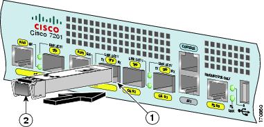
Figure 4-1 Inserting an SFP Module into the Cisco 7201 Gigabit Ethernet Port 0/1
|
|
Gigabit Ethernet port 0/1—SFP port |
|
SFP module |
Step 1 ![]() Attach an ESD-preventive wrist strap between you and an unpainted chassis surface.
Attach an ESD-preventive wrist strap between you and an unpainted chassis surface.
Step 2 ![]() Locate the label on the SFP module and turn the SFP module so the label is on top and the alignment groove is on the bottom.
Locate the label on the SFP module and turn the SFP module so the label is on top and the alignment groove is on the bottom.

Note ![]() The SFP module is keyed so that it cannot be inserted incorrectly.
The SFP module is keyed so that it cannot be inserted incorrectly.
Step 3 ![]() Insert the SFP module into Gigabit Ethernet port 0/0, 0/1, 0/2, or 0/3. The SFP module snaps into place when you have completely and properly inserted it.
Insert the SFP module into Gigabit Ethernet port 0/0, 0/1, 0/2, or 0/3. The SFP module snaps into place when you have completely and properly inserted it.
Step 4 ![]() Repeat Step 2 and Step 3 if you are inserting a second, third, or fourth SFP module.
Repeat Step 2 and Step 3 if you are inserting a second, third, or fourth SFP module.
Note ![]() Do not remove the plug from the SFP optical bores until you are ready to install the network interface optical fiber cable. Save the plug for future use.
Do not remove the plug from the SFP optical bores until you are ready to install the network interface optical fiber cable. Save the plug for future use.
Step 5 ![]() Clean the optical fiber cable before attaching it to the SFP module. For information, see the
Clean the optical fiber cable before attaching it to the SFP module. For information, see the
Inspection and Cleaning Procedures for Fiber-Optic Connections document at
http://www.cisco.com/en/US/tech/tk482/tk876/technologies_white_paper09186a0080254eba.shtml
and the Compressed Air Cleaning Issues for Fiber-Optic Connections document at
http://www.cisco.com/en/US/tech/tk482/tk611/technologies_white_paper09186a00801b08da.shtml
This completes the SFP module installation procedure.
Removing and Installing the CompactFlash Disk
For CompactFlash Disk specifications and product numbers, see Appendix A, "Specifications." For use of the CompactFlash Disk, also see Appendix B, "Using the CompactFlash Disk."
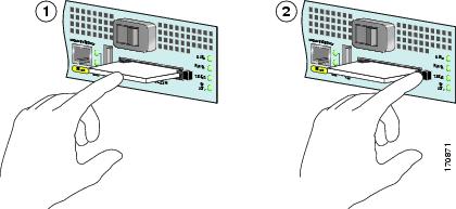
Figure 4-2 Installing and Removing a CompactFlash Disk
|
|
Inserting the CompactFlash Disk |
|
Pressing the ejector button to release the CompactFlash Disk |
To install a CompactFlash Disk in the CompactFlash Disk slot, complete the following steps.
Step 1 ![]() Orient the CompactFlash Disk so that its connector end faces the appropriate slot.
Orient the CompactFlash Disk so that its connector end faces the appropriate slot.
Step 2 ![]() Carefully insert the CompactFlash Disk into the slot until it completely seats in the connector, and the ejector button for the slot pops out toward you.
Carefully insert the CompactFlash Disk into the slot until it completely seats in the connector, and the ejector button for the slot pops out toward you.
Note ![]() The CompactFlash Disk is keyed and cannot be seated the wrong way. The ejector button does not pop out if the CompactFlash Disk is not completely inserted.
The CompactFlash Disk is keyed and cannot be seated the wrong way. The ejector button does not pop out if the CompactFlash Disk is not completely inserted.
This completes the CompactFlash Disk installation procedure. Also see Appendix B, "Using the CompactFlash Disk."
Removing and Installing a USB Flash Memory Module or
USB eToken Pro Key
For USB specifications and product numbers, see Appendix A, "Specifications." Also see the "USB Port Information" section on page 1-6.
Note ![]() Only Cisco USB Flash memory modules and the Aladdin USB eToken Pro key are supported by Cisco routers.
Only Cisco USB Flash memory modules and the Aladdin USB eToken Pro key are supported by Cisco routers.
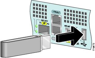
Figure 4-3 Connecting a USB Flash Memory Module to a Router USB Port

Step 1 ![]() To remove a USB Flash memory module or Alladin USB eToken Pro key, pull it from the USB port.
To remove a USB Flash memory module or Alladin USB eToken Pro key, pull it from the USB port.
Step 2 ![]() Insert a Cisco USB flash memory module or the Aladdin USB eToken Pro key into the Cisco 7201 USB port as shown in Figure 4-3. The USB Flash memory module can be inserted in only one way, and can be inserted or removed regardless of whether the router is powered on or not.
Insert a Cisco USB flash memory module or the Aladdin USB eToken Pro key into the Cisco 7201 USB port as shown in Figure 4-3. The USB Flash memory module can be inserted in only one way, and can be inserted or removed regardless of whether the router is powered on or not.
This completes the USB Flash memory or Aladdin USB eToken Pro key installation procedure.
Note ![]() For detailed information about the Cisco IOS commands that support USB Flash memory modules, see theUSB Storage document at http://www.cisco.com/en/US/docs/ios/12_3t/12_3t14/feature/guide/gt_etokn.html.
For detailed information about the Cisco IOS commands that support USB Flash memory modules, see theUSB Storage document at http://www.cisco.com/en/US/docs/ios/12_3t/12_3t14/feature/guide/gt_etokn.html.
Removing and Installing a Port Adapter or Service Adapter
The information in this section also applies to service adapters.
Warning ![]() During these procedures, wear grounding wrist straps to avoid ESD damage to the card. Do not directly touch the backplane with your hand or any metal tool, or you could shock yourself. Statement 94
During these procedures, wear grounding wrist straps to avoid ESD damage to the card. Do not directly touch the backplane with your hand or any metal tool, or you could shock yourself. Statement 94
Before removing any port adapter, gracefully shut down the interface so that there is no traffic running through the port adapter when it is removed. Removing a port adapter while traffic is flowing through the ports can cause system disruption.
The Cisco 7201 router supports OIR of the port adapter. However, if you choose to power off the router to remove or install a port adapter, turn the power switch to the standby (|) position and then remove the power cable. After you have replaced the port adapter or inserted a port adapter blank panel, replace the power cable and then turn the power switch to the on (O) position.
Note ![]() After powering off the router, wait at least 30 seconds before powering it on again.
After powering off the router, wait at least 30 seconds before powering it on again.
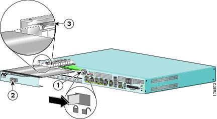
Figure 4-4 Installing a Port Adapter or Service Adapter
|
|
Port adapter lever |
|
Port adapter slot guide |
|
|
Port adapter |
Follow these steps for inserting and securing a port adapter:
Step 1 ![]() Attach an ESD-preventative wrist strap between you and an unpainted chassis surface.
Attach an ESD-preventative wrist strap between you and an unpainted chassis surface.
Step 2 ![]() Disconnect all cables from the port adapter.
Disconnect all cables from the port adapter.
Step 3 ![]() Remove the port adapter from the chassis slot by sliding the port adapter lever to the right, in the unlocked position.
Remove the port adapter from the chassis slot by sliding the port adapter lever to the right, in the unlocked position.
Step 4 ![]() Grasp the handle and pull the port adapter or port adapter blank panel from the router.
Grasp the handle and pull the port adapter or port adapter blank panel from the router.
Step 5 ![]() Locate the port adapter slot guides inside the Cisco 7201 router. They are near the top, and are recessed about one-half inch.
Locate the port adapter slot guides inside the Cisco 7201 router. They are near the top, and are recessed about one-half inch.
Step 6 ![]() Carefully slide the port adapter into the port adapter slot and seat it. When installed, the port adapter input/output panel should be flush with the face of the router.
Carefully slide the port adapter into the port adapter slot and seat it. When installed, the port adapter input/output panel should be flush with the face of the router.
Step 7 ![]() Slide the port adapter lever left to the locked position.
Slide the port adapter lever left to the locked position.
Step 8 ![]() Reconnect any cables, including the port adapter and power cables, and place the cables through any cable-management bracket or power cable-retention clip.
Reconnect any cables, including the port adapter and power cables, and place the cables through any cable-management bracket or power cable-retention clip.
Step 9 ![]() Power on the router by turning the power switch to the on (O) position.
Power on the router by turning the power switch to the on (O) position.
Note ![]() If the port adapter fails to come up, reseat or reinsert the port adapter: do not use excessive force.
If the port adapter fails to come up, reseat or reinsert the port adapter: do not use excessive force.
This completes the port adapter installation procedure. For information about configuring a port adapter, see the Cisco 7201 Port Adapter Documentation Roadmap, which provides a linked list of all port adapter documentation for the Cisco 7201 router, at http://www.cisco.com/en/US/docs/routers/7200/roadmaps/7201_port_adaper_doc_roadmap/11366pr.html
Removing and Installing an AC Power Supply
For AC power supply specifications and product numbers, see Appendix A, "Specifications."
This section provides information about removing and replacing an AC power supply. Because of the power supply redundancy, there is no need to power off the Cisco 7201 router before removing one of the AC power supplies.
The Cisco 7201 has two of the same type of power supplies in power supply slot 1 and power supply
slot 2. (See Figure 4-5.)
Figure 4-5 Power Supply Slot 1 and Slot 2
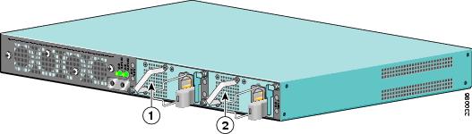
|
|
Power supply slot 1 |
|
Power supply slot 2 |
Removing the AC Power Supply
This section provides information about removing the AC power supply.
Step 1 ![]() On the front of the router, turn the power switch to the standby (|) position.
On the front of the router, turn the power switch to the standby (|) position.
Step 2 ![]() Unplug the power cable from the power source.
Unplug the power cable from the power source.
Figure 4-6 Removing the AC Power Cable
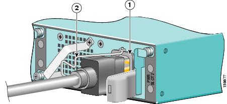
|
|
AC power receptacle |
|
AC power cable-retention clip |
Step 3 ![]() Swing the cable-retention clip to the left.
Swing the cable-retention clip to the left.
Step 4 ![]() Unplug the AC power cable from the power supply.
Unplug the AC power cable from the power supply.
Figure 4-7 Removing the AC Power Supply
|
|
Power up restrictor |
|
Lower power supply captive installation screw |
|
|
Upper power supply captive installation screw |
Step 5 ![]() Move the power up restrictor to the left to gain access to the upper power supply captive installation screw.
Move the power up restrictor to the left to gain access to the upper power supply captive installation screw.
Step 6 ![]() Unscrew the upper power supply captive installation screw while holding the power up restrictor to the left, then release the power up restrictor.
Unscrew the upper power supply captive installation screw while holding the power up restrictor to the left, then release the power up restrictor.
Step 7 ![]() Unscrew the lower power supply captive installation screw.
Unscrew the lower power supply captive installation screw.
Step 8 ![]() Grasping the captive installation screws, pull the power supply from the chassis.
Grasping the captive installation screws, pull the power supply from the chassis.
You are finished removing the AC power supply. To install the AC power supply, go to the "Installing the AC Power Supply" section.
Installing the AC Power Supply
This section provides information about installing an AC power supply in the Cisco 7201 router.
Warning ![]() Never install an AC power module and a DC power module in the same chassis. Statement 1050
Never install an AC power module and a DC power module in the same chassis. Statement 1050
Warning ![]() Installation of the equipment must comply with local and national electrical codes. Statement 1074
Installation of the equipment must comply with local and national electrical codes. Statement 1074
Figure 4-8 Installing the AC Power Supply
|
|
Power up restrictor |
|
Lower power supply captive installation screw |
|
|
Upper power supply captive installation screw |
Step 1 ![]() Insert an AC power supply in power supply slot 1 or power supply slot 2 until it is fully seated.
Insert an AC power supply in power supply slot 1 or power supply slot 2 until it is fully seated.
Step 2 ![]() Tighten the captive installation screws.
Tighten the captive installation screws.
a. ![]() Tighten the lower power supply captive installation screw.
Tighten the lower power supply captive installation screw.
b. ![]() Push the power up restrictor to the left to allow you to tighten the upper power supply captive installation screw. Tighten the upper power supply captive installation screw.
Push the power up restrictor to the left to allow you to tighten the upper power supply captive installation screw. Tighten the upper power supply captive installation screw.
c. ![]() Release the power up restrictor so that it again covers the upper power supply captive installation screw.
Release the power up restrictor so that it again covers the upper power supply captive installation screw.
Step 3 ![]() Slide the wire cable-retention clip to the left.
Slide the wire cable-retention clip to the left.
Step 4 ![]() Insert the AC power cable.
Insert the AC power cable.
Step 5 ![]() Slide the wire cable-retention clip to the right, over the power supply cable.
Slide the wire cable-retention clip to the right, over the power supply cable.
Step 6 ![]() Plug the power supply cable into the power source.
Plug the power supply cable into the power source.
Step 7 ![]() On the front of the router, place the power switch in the on (O) position to turn on the router.
On the front of the router, place the power switch in the on (O) position to turn on the router.
You are finished replacing the AC power supply.
Removing and Installing a DC Power Supply
For DC power supply specifications and product numbers, see Appendix A, "Specifications".
This section provides information about removing and replacing a DC power supply. Because of the power supply redundancy, there is no need to power off the Cisco 7201 router before removing one of the DC power supplies.
The Cisco 7201 has two of the same type of power supplies in power supply slot 1 and power supply
slot 2. (See Figure 4-5.) The power supply slot numbers are on the chassis to the left of the left power supply, and to the right of the right power supply.
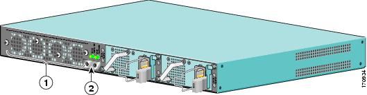
Figure 4-9 Power Supply Slot 1 and Slot 2
|
|
Power supply slot 1 |
|
Power supply slot 2 |
Removing the DC Power Supply
Warning ![]() Before performing any of the following procedures, ensure that power is removed from the DC circuit. Statement 1003
Before performing any of the following procedures, ensure that power is removed from the DC circuit. Statement 1003
Warning ![]() Only trained and qualified personnel should be allowed to install, replace, or service this equipment. Statement 1030
Only trained and qualified personnel should be allowed to install, replace, or service this equipment. Statement 1030
Warning ![]() Installation of the equipment must comply with local and national electrical codes. Statement 1074
Installation of the equipment must comply with local and national electrical codes. Statement 1074
Figure 4-10 Removing the Ground Lugs
Step 1 ![]() On the front of the router, turn the power switch to the standby (|) position.
On the front of the router, turn the power switch to the standby (|) position.
Step 2 ![]() Switch the circuit breaker to the off position, and tape the switch handle to the off position.
Switch the circuit breaker to the off position, and tape the switch handle to the off position.
Step 3 ![]() Pull the terminal block plug from the terminal block.
Pull the terminal block plug from the terminal block.
Step 4 ![]() Locate the DC power supply grounding stud.
Locate the DC power supply grounding stud.
Step 5 ![]() Remove the nut, ground lug, star washer, ground lug, and star washer and save for reuse on the new DC power supply.
Remove the nut, ground lug, star washer, ground lug, and star washer and save for reuse on the new DC power supply.
Step 6 ![]() Move the power up restrictor to the left to gain access to the upper power supply captive installation screw.
Move the power up restrictor to the left to gain access to the upper power supply captive installation screw.
Step 7 ![]() Use a Number 2 Phillips screwdriver to unscrew the upper power supply captive installation screw.
Use a Number 2 Phillips screwdriver to unscrew the upper power supply captive installation screw.
Step 8 ![]() Unscrew the lower power supply captive installation screw on the lower left of the power supply.
Unscrew the lower power supply captive installation screw on the lower left of the power supply.
Step 9 ![]() Grasping the captive installation screws, pull the power supply from the chassis.
Grasping the captive installation screws, pull the power supply from the chassis.
This complete the procedure for removing the DC power supply.
Installing the DC Power Supply
Warning ![]() This product relies on the building's installation for short-circuit (overcurrent) protection. Ensure that the protective device is rated not greater than: 120 VAC, 20A U.S. (240 VAC, 10A international). Statement 1005
This product relies on the building's installation for short-circuit (overcurrent) protection. Ensure that the protective device is rated not greater than: 120 VAC, 20A U.S. (240 VAC, 10A international). Statement 1005
Warning ![]() Never install an AC power module and a DC power module in the same chassis. Statement 1050
Never install an AC power module and a DC power module in the same chassis. Statement 1050
This section provides instructions for installing the DC power supply ground leads and installing the DC-input power leads.
Warning ![]() This equipment must be grounded. Never defeat the ground conductor or operate the equipment in the absence of a suitably installed ground conductor. Contact the appropriate electrical inspection authority or an electrician if you are uncertain that suitable grounding is available. Statement 1024
This equipment must be grounded. Never defeat the ground conductor or operate the equipment in the absence of a suitably installed ground conductor. Contact the appropriate electrical inspection authority or an electrician if you are uncertain that suitable grounding is available. Statement 1024
Obtain these necessary tools and equipment:
•![]() Ratcheting torque screwdriver with a Phillips head that exerts up to 15 pound force-inches (lbf in.) or 240 ounce force-inches (ozf in.) of pressure
Ratcheting torque screwdriver with a Phillips head that exerts up to 15 pound force-inches (lbf in.) or 240 ounce force-inches (ozf in.) of pressure
•![]() Panduit crimping tool with optional controlled cycle mechanism
Panduit crimping tool with optional controlled cycle mechanism
•![]() 18-gauge copper ground wire (insulated or noninsulated)
18-gauge copper ground wire (insulated or noninsulated)
•![]() Four leads of 18-gauge copper wire
Four leads of 18-gauge copper wire
•![]() Wire-stripping tool for stripping 18-gauge wire
Wire-stripping tool for stripping 18-gauge wire
To install the DC power supply, follow these instructions:
Step 1 ![]() Slide the DC power supply into the chassis.
Slide the DC power supply into the chassis.
Step 2 ![]() Move the power up restrictor to the left to gain access to the upper power supply captive installation screw.
Move the power up restrictor to the left to gain access to the upper power supply captive installation screw.
Step 3 ![]() Hold the power up restrictor to the left, while using a Number 2 Phillips screwdriver to tighten the upper power supply captive installation screw.
Hold the power up restrictor to the left, while using a Number 2 Phillips screwdriver to tighten the upper power supply captive installation screw.
Step 4 ![]() Tighten the lower power supply captive installation screw on the lower left of the power supply.
Tighten the lower power supply captive installation screw on the lower left of the power supply.
Go to the "Installing the DC Grounding Leads" section to continue the DC power supply installation procedure.
Installing the DC Grounding Leads
To install the DC grounding leads on the DC power supply, follow these instructions.
The DC power supply ships with the DC power supply ground lugs, star washers, and nut attached to the grounding stud on the DC power supply.
•![]() If you are going to use the new ground lug and attach it to new ground wire, see the "Installing the DC Grounding Leads" section on page 2-27.
If you are going to use the new ground lug and attach it to new ground wire, see the "Installing the DC Grounding Leads" section on page 2-27.
•![]() If you are going to use the current ground lug and ground wire with the new DC power supply, follow the instructions below.
If you are going to use the current ground lug and ground wire with the new DC power supply, follow the instructions below.
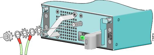
Figure 4-11 Locating the DC Grounding Stud and Grounding Materials
Step 1 ![]() Locate the grounding stud on the DC power supply.
Locate the grounding stud on the DC power supply.
Step 2 ![]() Using the ground lugs from the previous power supply, replace them and the star washers and nut in the following order:
Using the ground lugs from the previous power supply, replace them and the star washers and nut in the following order:
a. ![]() Star washer
Star washer
b. ![]() Ground lug with ground wire
Ground lug with ground wire
c. ![]() Star washer
Star washer
d. ![]() Ground lug with ground wire
Ground lug with ground wire
e. ![]() Nut
Nut
Note ![]() If you are using the new lugs that came with the new DC power supply, see the "Installing the DC Grounding Leads" section on page 2-27 for instructions on wiring the ground lugs and ground wires.
If you are using the new lugs that came with the new DC power supply, see the "Installing the DC Grounding Leads" section on page 2-27 for instructions on wiring the ground lugs and ground wires.
Step 3 ![]() Tighten the nut to complete the installation.
Tighten the nut to complete the installation.
To continue the DC power supply installation procedure, go to the "Wiring the DC-Input Power Source" section.
Wiring the DC-Input Power Source
Note ![]() The color coding of the DC-input power supply leads depends on the color coding of the DC power source at your site. Make certain the lead color coding you choose for the DC-input power supply matches lead color coding used at the DC power source.
The color coding of the DC-input power supply leads depends on the color coding of the DC power source at your site. Make certain the lead color coding you choose for the DC-input power supply matches lead color coding used at the DC power source.
Warning ![]() When you install the unit, the ground connection must always be made first and disconnected last. Statement 1046
When you install the unit, the ground connection must always be made first and disconnected last. Statement 1046
Warning ![]() This product relies on the building's installation for short-circuit (overcurrent) protection. Ensure that the protective device is rated not greater than: 120 VAC, 20A U.S. (240 VAC, 10A international). Statement 1005
This product relies on the building's installation for short-circuit (overcurrent) protection. Ensure that the protective device is rated not greater than: 120 VAC, 20A U.S. (240 VAC, 10A international). Statement 1005
Warning ![]() Before performing any of the following procedures, ensure that power is removed from the DC circuit. Statement 1003
Before performing any of the following procedures, ensure that power is removed from the DC circuit. Statement 1003
Warning ![]() Only trained and qualified personnel should be allowed to install, replace, or service this equipment. Statement 1030
Only trained and qualified personnel should be allowed to install, replace, or service this equipment. Statement 1030
Step 1 ![]() At the front of the router, make sure the power switch is in the standby (|) position.
At the front of the router, make sure the power switch is in the standby (|) position.
Step 2 ![]() Check to make sure the power supply LEDs are off.
Check to make sure the power supply LEDs are off.
Step 3 ![]() Move the circuit-breaker switch handle to the off position, and apply tape to hold it in the off position.
Move the circuit-breaker switch handle to the off position, and apply tape to hold it in the off position.
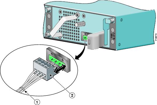
Figure 4-12 Inserting the Terminal Block Plug in the Block Header
|
|
Tie wrap |
|
Terminal block plug |
Step 4 ![]() Use a tie wrap to secure the wires to the rack, so that the wires are not pulled from the terminal block plug by casual contact. Make sure the tie wrap allows for some slack in the ground wire.
Use a tie wrap to secure the wires to the rack, so that the wires are not pulled from the terminal block plug by casual contact. Make sure the tie wrap allows for some slack in the ground wire.
Step 5 ![]() Insert the terminal block plug in the terminal block header on the DC power supply panel, as shown in Figure 4-12.
Insert the terminal block plug in the terminal block header on the DC power supply panel, as shown in Figure 4-12.
Step 6 ![]() Repeat Step 1 through Step 4 if you are replacing a second DC power supply.
Repeat Step 1 through Step 4 if you are replacing a second DC power supply.
Step 7 ![]() Remove the tape from the circuit-breaker switch handle, and move the circuit-breaker switch handle to the on position.
Remove the tape from the circuit-breaker switch handle, and move the circuit-breaker switch handle to the on position.
Step 8 ![]() On the front of the router, place the power switch in the on (O) position to turn on the router.
On the front of the router, place the power switch in the on (O) position to turn on the router.
Note ![]() After powering off the router, wait a minimum of 30 seconds before powering it on again.
After powering off the router, wait a minimum of 30 seconds before powering it on again.
You are finished installing the DC power supply.
Removing and Installing a DIMM
To remove and replace a SDRAM DIMM, use the information in this section. SDRAM specifications are in Appendix A, "Specifications."
Powering Off the Router and Removing the Cover
This section provides information for powering off the router and removing the cover.
Warning ![]() During these procedures, wear grounding wrist straps to avoid ESD damage to the card. Do not directly touch the backplane with your hand or any metal tool, or you could shock yourself.
During these procedures, wear grounding wrist straps to avoid ESD damage to the card. Do not directly touch the backplane with your hand or any metal tool, or you could shock yourself.
Statement 94
Warning ![]() This unit might have more than one power supply connection. All connections must be removed to de-energize the unit. Statement 1028
This unit might have more than one power supply connection. All connections must be removed to de-energize the unit. Statement 1028
Step 1 ![]() Attach an ESD-preventative wrist or ankle strap, connecting the equipment end of the strap to an unfinished chassis surface.
Attach an ESD-preventative wrist or ankle strap, connecting the equipment end of the strap to an unfinished chassis surface.
Step 2 ![]() Power off the router by turning the power switch to the standby (|) position.
Power off the router by turning the power switch to the standby (|) position.
Note ![]() After powering off the router, wait a minimum of 30 seconds before powering it on again.
After powering off the router, wait a minimum of 30 seconds before powering it on again.
Step 3 ![]() Remove any power and input/output cables from the Cisco 7201 router. For AC power supplies, unplug the AC power cord from the power outlet. For DC power supplies, to ensure that all power is off, locate the circuit breaker on the panel board that services the DC circuit, switch the circuit breaker to the off position, tape the switch handle of the circuit breaker in the off position, and remove the DC connector.
Remove any power and input/output cables from the Cisco 7201 router. For AC power supplies, unplug the AC power cord from the power outlet. For DC power supplies, to ensure that all power is off, locate the circuit breaker on the panel board that services the DC circuit, switch the circuit breaker to the off position, tape the switch handle of the circuit breaker in the off position, and remove the DC connector.
Step 4 ![]() Remove the ground cable.
Remove the ground cable.
Step 5 ![]() Remove the Cisco 7201 router from the rack, if it is rack-mounted.
Remove the Cisco 7201 router from the rack, if it is rack-mounted.
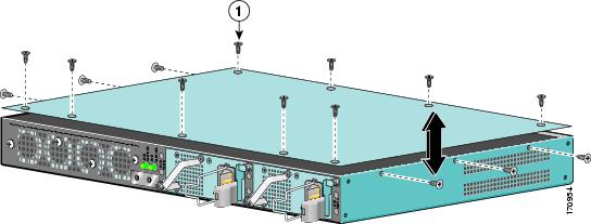
Figure 4-13 Removing the Cover
|
|
Cover screws |
Step 6 ![]() Turn the Cisco 7201 so that the back is facing you.
Turn the Cisco 7201 so that the back is facing you.
Step 7 ![]() Using a Phillips screwdriver, loosen the fifteen cover screws holding the cover to the chassis.
Using a Phillips screwdriver, loosen the fifteen cover screws holding the cover to the chassis.
Step 8 ![]() Lift the cover off the router.
Lift the cover off the router.
Proceed to the following sections for replacement instructions:
•![]() Removing and Installing the DIMM
Removing and Installing the DIMM
•![]() Replacing the Cover and Powering On the Router
Replacing the Cover and Powering On the Router
Removing and Installing the DIMM
The information in this section provides instructions for replacing the DDR-SDRAM DIMM and is included for future use. The memory configuration you ordered is installed in the Cisco 7201 router.
Warning ![]() During these procedures, wear grounding wrist straps to avoid ESD damage to the card. Do not directly touch the backplane with your hand or any metal tool, or you could shock yourself.
During these procedures, wear grounding wrist straps to avoid ESD damage to the card. Do not directly touch the backplane with your hand or any metal tool, or you could shock yourself.
Statement 94
To replace or upgrade the DIMM, follow these instructions:
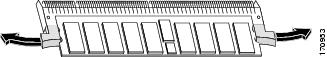
Figure 4-14 Removing and Replacing the DIMM
Note ![]() Use only a DDR-SDRAM DIMM purchased from Cisco.
Use only a DDR-SDRAM DIMM purchased from Cisco.
Step 1 ![]() Attach an ESD-preventative wrist strap between you and an unpainted router surface.
Attach an ESD-preventative wrist strap between you and an unpainted router surface.
Step 2 ![]() Locate the DIMM on the system board.
Locate the DIMM on the system board.
Step 3 ![]() Press both spring latches outward to release the DIMM.
Press both spring latches outward to release the DIMM.
Step 4 ![]() Gently pull the DIMM free from the DIMM socket, taking care not to touch the pins that insert into the socket. Place the DIMM in an anti-static bag.
Gently pull the DIMM free from the DIMM socket, taking care not to touch the pins that insert into the socket. Place the DIMM in an anti-static bag.
Step 5 ![]() Locate the notches and align the DIMM with the socket before inserting it.
Locate the notches and align the DIMM with the socket before inserting it.
Step 6 ![]() Gently insert the new DIMM, taking care not to damage the pins on the edge of the DIMM.
Gently insert the new DIMM, taking care not to damage the pins on the edge of the DIMM.
Step 7 ![]() Press down on the DIMM until the spring latches lock the DIMM in place.
Press down on the DIMM until the spring latches lock the DIMM in place.
Go to the "Replacing the Cover and Powering On the Router" section to complete this installation procedure.
For memory specifications and configurations, see Appendix A, "Specifications."
Replacing the Cover and Powering On the Router
The Cisco 7201 router cover fits tightly on the chassis. Follow these instructions to replace the cover and power on the router:
Figure 4-15 Inserting the Screws and Replacing the Cover
|
|
Cover screws |
Step 1 ![]() Place the cover on the top of the router with the four-screw edge aligned with the front of the router, and the five-screw edge aligned with the rear of the router.
Place the cover on the top of the router with the four-screw edge aligned with the front of the router, and the five-screw edge aligned with the rear of the router.
Step 2 ![]() Insert and tighten the fifteen cover screws with a Phillips screwdriver.
Insert and tighten the fifteen cover screws with a Phillips screwdriver.
Step 3 ![]() Return the router to its installation site, attach the ground cable, and input/output and power cables.
Return the router to its installation site, attach the ground cable, and input/output and power cables.
Step 4 ![]() Power on the router by turning the power switch to the on position.
Power on the router by turning the power switch to the on position.
This completes the installation of the DIMM and replacement of the cover.
 Feedback