Cisco 7201 Installation and Configuration Guide
Bias-Free Language
The documentation set for this product strives to use bias-free language. For the purposes of this documentation set, bias-free is defined as language that does not imply discrimination based on age, disability, gender, racial identity, ethnic identity, sexual orientation, socioeconomic status, and intersectionality. Exceptions may be present in the documentation due to language that is hardcoded in the user interfaces of the product software, language used based on RFP documentation, or language that is used by a referenced third-party product. Learn more about how Cisco is using Inclusive Language.
- Updated:
- December 9, 2008
Chapter: Overview
Overview
The Cisco 7201 router provides application-specific features for broadband subscriber aggregation and network application services with high processing performance.
This chapter provides a quick hardware and features overview and options installation instructions for the Cisco 7201 router. For functional information, see Chapter 3, "Starting and Configuring the Router," the "Functional Overview" section on page 3-1. For system specifications and port and cabling specifications, see Appendix A, "Specifications."
This chapter includes the following sections:
•![]() Checking the Shipping Container Contents
Checking the Shipping Container Contents
•![]() Cisco 7201 Router Installation Checklist
Cisco 7201 Router Installation Checklist

Warning ![]() This warning symbol means danger. You are in a situation that could cause bodily injury. Before you work on any equipment, be aware of the hazards involved with electrical circuitry and be familiar with standard practices for preventing accidents. Use the statement number provided at the end of each warning to locate its translation in the translated safety warnings that accompanied this device. Statement 1071
This warning symbol means danger. You are in a situation that could cause bodily injury. Before you work on any equipment, be aware of the hazards involved with electrical circuitry and be familiar with standard practices for preventing accidents. Use the statement number provided at the end of each warning to locate its translation in the translated safety warnings that accompanied this device. Statement 1071
Warning ![]() Before you install, operate, or service the system, read the Regulatory Compliance and Safety Information for Cisco 7200 Series Routers publication. This document provides important safety information you should know before working with the system. Statement 200
Before you install, operate, or service the system, read the Regulatory Compliance and Safety Information for Cisco 7200 Series Routers publication. This document provides important safety information you should know before working with the system. Statement 200
Cisco 7201 Features
The Cisco 7201 router consists of the following features:
•![]() Small form-factor—One rack-unit (RU) high with stacking capability:
Small form-factor—One rack-unit (RU) high with stacking capability:
1.73 in. x 17.3 in. x 16.2 in. (4.39 cm x 43.94 cm x 41.20 cm) (H x W x D). The weight is approximately 16.5 lb (7.48 kg).
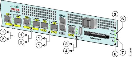
•![]() Four native Gigabit Ethernet interfaces—Six physical access ports:
Four native Gigabit Ethernet interfaces—Six physical access ports:
–![]() Four optical fiber Gigabit Ethernet (1000 Mbps) ports that use small form-factor pluggable (SFP) modules with LC connectors. Gigabit Ethernet ports 0, 1, and 2 support 10/100/1000 Mbps, and ports 2 and 3 support only 1000 Mbps.
Four optical fiber Gigabit Ethernet (1000 Mbps) ports that use small form-factor pluggable (SFP) modules with LC connectors. Gigabit Ethernet ports 0, 1, and 2 support 10/100/1000 Mbps, and ports 2 and 3 support only 1000 Mbps.
–![]() Two Gigabit Ethernet (10/100/1000 Mbps) ports with RJ-45 connectors (The use of an RJ-45 port or SFP port on a common Gigabit Ethernet interface is mutually exclusive at any one time.)
Two Gigabit Ethernet (10/100/1000 Mbps) ports with RJ-45 connectors (The use of an RJ-45 port or SFP port on a common Gigabit Ethernet interface is mutually exclusive at any one time.)
•![]() One 10/100-Mbps Fast Ethernet Management port—To be used only as a management port; not to be used as a Fast Ethernet interface port
One 10/100-Mbps Fast Ethernet Management port—To be used only as a management port; not to be used as a Fast Ethernet interface port
•![]() Both 25-MHz and 50-MHz port adapter operation
Both 25-MHz and 50-MHz port adapter operation
•![]() A 256-MB CompactFlash Disk
A 256-MB CompactFlash Disk
•![]() One USB port for data storage, supporting 64-, 128-, and 256-MB data storage modules, and supporting the 32-Kb Aladdin USB eToken Pro Key for VPN applications
One USB port for data storage, supporting 64-, 128-, and 256-MB data storage modules, and supporting the 32-Kb Aladdin USB eToken Pro Key for VPN applications
•![]() SFP modules: Four Gigabit Ethernet SX, LH/LX, ZX , and FX module options supported on all four Gigabit Ethernet ports, and one 1000BASE-T SFP (copper) module supported only on ports GE 0/2 and GE 0/3
SFP modules: Four Gigabit Ethernet SX, LH/LX, ZX , and FX module options supported on all four Gigabit Ethernet ports, and one 1000BASE-T SFP (copper) module supported only on ports GE 0/2 and GE 0/3
•![]() Dual AC power or dual DC power supplies
Dual AC power or dual DC power supplies
•![]() Freescale 7448 processor that operates at an internal clock speed of 1.67 GHz
Freescale 7448 processor that operates at an internal clock speed of 1.67 GHz
•![]() Two levels of cache memory: primary and secondary cache that are internal to the microprocessor with secondary unified cache for data and instruction
Two levels of cache memory: primary and secondary cache that are internal to the microprocessor with secondary unified cache for data and instruction
•![]() One system controller that provides the connectivity between the processor and surrounding subsystems, including PCI busses, the DDR-SDRAM DIMM, the native Gigabit Ethernet interfaces, and the local bus with the various slow speed control and interface logic
One system controller that provides the connectivity between the processor and surrounding subsystems, including PCI busses, the DDR-SDRAM DIMM, the native Gigabit Ethernet interfaces, and the local bus with the various slow speed control and interface logic
•![]() 3-MB Boot ROM for storing the ROMmon images
3-MB Boot ROM for storing the ROMmon images
•![]() Internal flash memory for storing the boot helper (boot loader) image and the Cisco IOS image
Internal flash memory for storing the boot helper (boot loader) image and the Cisco IOS image
•![]() Two SDRAM memory options: 1 GB and 2 GB
Two SDRAM memory options: 1 GB and 2 GB
•![]() 2-MB NVRAM for storing the system configuration and environmental monitoring logs
2-MB NVRAM for storing the system configuration and environmental monitoring logs
•![]() Auxiliary port with full data terminal equipment (DTE) functionality
Auxiliary port with full data terminal equipment (DTE) functionality
•![]() Console port with full data communications equipment (DCE) functionality
Console port with full data communications equipment (DCE) functionality
•![]() Online insertion and removal (OIR)—Allows you to add, replace, or remove port adapters with minimal interruption of the system
Online insertion and removal (OIR)—Allows you to add, replace, or remove port adapters with minimal interruption of the system
•![]() Software support: Cisco IOS Release 12.4(4)XD7, Cisco IOS Release 12.2(31)SB5, and
Software support: Cisco IOS Release 12.4(4)XD7, Cisco IOS Release 12.2(31)SB5, and
Cisco IOS Release 12.4(15)T1
•![]() Environmental monitoring and reporting functions—Allow you to maintain normal system operation by resolving adverse environmental conditions prior to loss of operation
Environmental monitoring and reporting functions—Allow you to maintain normal system operation by resolving adverse environmental conditions prior to loss of operation
•![]() Downloadable software—Allows you to load new images into flash memory remotely, without having to physically access the router, for fast, reliable upgrades
Downloadable software—Allows you to load new images into flash memory remotely, without having to physically access the router, for fast, reliable upgrades
•![]() Front-to-back airflow—Allows you to mount the router from either front or back into 19-inch equipment racks and 23-inch equipment racks
Front-to-back airflow—Allows you to mount the router from either front or back into 19-inch equipment racks and 23-inch equipment racks
Cisco 7201 Hardware Overview
This section provides an overview of the hardware, including LEDs, front and rear views, and interior component identification.
Front View
The faceplate of the Cisco 7201 router is described in this section.
Figure 1-1 Cisco 7201 Router—Front View

Faceplate LEDs
The Cisco 7201 router LEDs and behaviors are described in this section.
Figure 1-2 Cisco 7201 Router—Faceplate LEDs
SFP Module Information
You may have ordered a small form-factor pluggable (SFP) module with your Cisco 7201 router. You must install the SFP module. It is shipped separately to prevent damage during shipment. After reading this section, use the installation instructions in the "Removing and Installing an SFP Module" section on page 4-2 to install the SFP modules.
For ease of installation, insert the SFP module in the router while it is powered down and before placing it in a rack.
The SFP port is a 1000-Mbps optical interface in the form of an LC-type duplex port that supports IEEE 802.3z interfaces compliant with the 1000BASEX standard. Gigabit Ethernet SFP models SFP-GE-S, SFP-GE-L, SFP-GE-Z, and SFP-GE-Fare supported in the Cisco 7201 router, as well as the SFP-GE-T. The cabling information is the same for all optical SFP modules.
Also see the "SFP Module Specifications and Configurations" section on page A-4, and the Gigabit Interface Converter (GBIC) Module and Small Form-Factor Pluggable (SFP) GBIC Module Installation Information and Specifications document at
http://www.cisco.com/en/US/docs/routers/7200/install_and_upgrade/gbic_sfp_modules_install/5067g.html
For optical connection cleaning information, see the
Inspection and Cleaning Procedures for Fiber-Optic Connections document at
http://www.cisco.com/en/US/tech/tk482/tk876/technologies_white_paper09186a0080254eba.shtml
and the Compressed Air Cleaning Issues for Fiber-Optic Connections document at
http://www.cisco.com/en/US/tech/tk482/tk611/technologies_white_paper09186a00801b08da.shtml
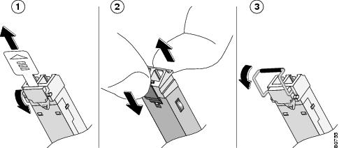
Figure 1-3 Types of SFP Module Latches
|
|
Sliding latch |
|
Swing latch |
|
|
Swing and slide latch |

Note ![]() The SFP module must be installed before you connect the cables to it.
The SFP module must be installed before you connect the cables to it.
•![]() The SPF module has three types of latches, which are also the removal mechanism. See Figure 1-3. There is no correlation of the type of latch to the model (such as SX or LH/LX) or technology type (such as Gigabit Ethernet) of SFP modules. Always read the label on the SFP module to determine the technology type and model.
The SPF module has three types of latches, which are also the removal mechanism. See Figure 1-3. There is no correlation of the type of latch to the model (such as SX or LH/LX) or technology type (such as Gigabit Ethernet) of SFP modules. Always read the label on the SFP module to determine the technology type and model.
•![]() You can install and remove Gigabit Ethernet SFP modules with power on to the system.
You can install and remove Gigabit Ethernet SFP modules with power on to the system.
Warning ![]() Invisible laser radiation may be emitted from disconnected fibers or connectors. Do not stare into beams or view directly with optical instruments. Statement 1051
Invisible laser radiation may be emitted from disconnected fibers or connectors. Do not stare into beams or view directly with optical instruments. Statement 1051
Warning ![]() Class 1 laser product. Statement 1008
Class 1 laser product. Statement 1008
Warning ![]() Class 1 LED product. Statement 1027
Class 1 LED product. Statement 1027
•![]() Disconnect all cables before removing or installing a Gigabit Ethernet SFP module. We strongly recommend that you do not install or remove the SFP module with optical fiber cables attached to it.
Disconnect all cables before removing or installing a Gigabit Ethernet SFP module. We strongly recommend that you do not install or remove the SFP module with optical fiber cables attached to it.
•![]() SFP modules are keyed to prevent incorrect insertion.
SFP modules are keyed to prevent incorrect insertion.
USB Port Information
The Cisco 7201 provides a USB port that can be used with a USB Flash memory module as secondary storage, and can be used to store Cisco IOS images, data, and configuration files. The Cisco 7201 USB port can also be used with the Aladdin USB eToken Pro key. This USB device can be used for the following functions:
•![]() The Cisco USB Flash memory module can be used to store an image or configuration file like a CompactFlash Disk. Unlike the Aladdin USB eToken Pro key, the Cisco USB Flash memory module is nonsecure. See Table A-5 on page A-4 for available USB token configurations and product numbers.
The Cisco USB Flash memory module can be used to store an image or configuration file like a CompactFlash Disk. Unlike the Aladdin USB eToken Pro key, the Cisco USB Flash memory module is nonsecure. See Table A-5 on page A-4 for available USB token configurations and product numbers.
•![]() The USB eToken Pro key by Aladdin Knowledge Systems provides a secure means to store and deploy information, such as a bootstrap configuration or VPN credentials, separate from the router chassis. The Aladdin USB eToken Pro key uses smart card technology to protect a small area of memory and grants access using a personal identification number (PIN). When IP Security (IPSec) VPN credentials are stored on the Aladdin USB eToken Pro key, they are safely external to the router. When the USB eToken is inserted in a USB port, the router can pass the PIN and unlock it, retrieving the credentials and copying them into running memory. When the Aladdin USB eToken Pro key is removed, the router erases the credentials from running memory, ensuring that they cannot be retrieved from the router itself.
The USB eToken Pro key by Aladdin Knowledge Systems provides a secure means to store and deploy information, such as a bootstrap configuration or VPN credentials, separate from the router chassis. The Aladdin USB eToken Pro key uses smart card technology to protect a small area of memory and grants access using a personal identification number (PIN). When IP Security (IPSec) VPN credentials are stored on the Aladdin USB eToken Pro key, they are safely external to the router. When the USB eToken is inserted in a USB port, the router can pass the PIN and unlock it, retrieving the credentials and copying them into running memory. When the Aladdin USB eToken Pro key is removed, the router erases the credentials from running memory, ensuring that they cannot be retrieved from the router itself.
Note ![]() For more information about the eToken Pro key by Aladdin Knowledge Systems, see the Aladdin website at www.aladdin.com/etoken/cisco.
For more information about the eToken Pro key by Aladdin Knowledge Systems, see the Aladdin website at www.aladdin.com/etoken/cisco.
Note ![]() The Cisco USB Flash memory module cannot be used to boot the router. The USB drivers exist only in Cisco IOS software, not ROM Monitor mode (ROMmon). As a result, a Cisco IOS image must be booted to load the drivers; only then can files be copied to and from the USB Flash memory module.
The Cisco USB Flash memory module cannot be used to boot the router. The USB drivers exist only in Cisco IOS software, not ROM Monitor mode (ROMmon). As a result, a Cisco IOS image must be booted to load the drivers; only then can files be copied to and from the USB Flash memory module.
CompactFlash Disk Information
The Cisco 7201 router has one CompactFlash Disk slot that uses CompactFlash Disks. The device in this slot is always addressed as disk0: when using Cisco IOS command-line interface (CLI) commands.
CompactFlash Disks are smaller in size than Type 2 Flash Disks but provide the same AT Attachment (ATA) interface and equivalent functionality. This interface complies with the ANSI ATA Interface Document X3T13.1153 D Rev. 9 specification. CompactFlash Disks provide from 256 MB of storage.
The CompactFlash Disk has controller circuitry that allows it to emulate a hard disk and automatically maps out bad blocks and performs automatic block erasure. The CompactFlash Disk also provides the capability to allocate noncontiguous sectors, which eliminates the need for the squeeze command (which was required with older-style linear flash memory cards to recover the space used by deleted files).
The CompactFlash Disk also supports the Cisco IOS File System feature, which provides a single interface to all of the router's file systems, including the Flash Disks and flash memory, as well as network file systems such as File Transfer Protocol (FTP) and Trivial FTP (TFTP) servers.
Table A-4 on page A-3 lists the CompactFlash Disk options. Also see Appendix B, "Using the CompactFlash Disk."
Rear View
This section provides information about the power supplies and fans on the rear of the Cisco 7201 router.
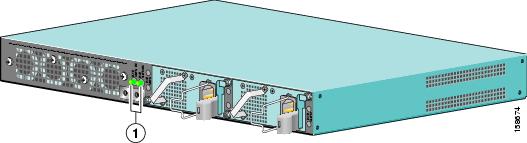
Figure 1-4 Cisco 7201—Rear View

|
|
Fans |
|
Power supply slot 1 |
|
|
Chassis ground connector |
|
Power supply slot 2 |
Four internal fans draw cooling air into the chassis and across internal components to maintain an acceptable operating temperature. (See Figure 1-4.) The four fans are located at the rear of the chassis, as is the chassis grounding connector that provides a chassis ground connection for ESD equipment or a two-hole grounding lug. Two power supplies, either two AC power supplies or two DC power supplies, are accessed from the rear of the router.
Power Supply LEDs
The power supply LEDs are to the left of the power supplies on the rear of the chassis.
Figure 1-5 Power Supply LEDs
Interior View
This section describes the Cisco 7201 interior components and their locations.
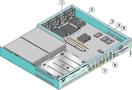
Figure 1-6 Cisco 7201 Router—Interior View
|
|
Temperature sensor (outlet—U20) |
|
Flash memory (U13) |
|
|
Freescale 7448 processor |
|
Temperature sensor (inlet—U12) |
|
|
Boot ROM (U24) |
|
DIMM (U16) |
|
|
Flash memory (U19) |
On the underside of the board is NVRAM (U77) and flash memory (U67, U70).
System Board
Internally, the system board contains the following components:
•![]() One DDR-SDRAM memory module (DIMM) for providing code, data, and packet storage
One DDR-SDRAM memory module (DIMM) for providing code, data, and packet storage
•![]() The Freescale 7448 processor
The Freescale 7448 processor
•![]() Marvel Discovery III—Hardware logic to interconnect the processor, double data rate synchronous dynamic random-access memory (DDR-SDRAM), dual PCI /PCI-X buses, three direct-interface Gigabit Ethernet interfaces, and a generic device bus
Marvel Discovery III—Hardware logic to interconnect the processor, double data rate synchronous dynamic random-access memory (DDR-SDRAM), dual PCI /PCI-X buses, three direct-interface Gigabit Ethernet interfaces, and a generic device bus
•![]() Cache memory
Cache memory
The processor system has two levels of cache: primary and secondary cache that are internal to the microprocessor with secondary unified cache for data and instruction.
•![]() Four Gigabit Ethernet interfaces (six ports: four SFP [optical] and two RJ-45s [copper]). Only four ports are available at the same time.
Four Gigabit Ethernet interfaces (six ports: four SFP [optical] and two RJ-45s [copper]). Only four ports are available at the same time.
•![]() One Fast Ethernet Management port
One Fast Ethernet Management port
•![]() A CompactFlash Disk for storing the default Cisco IOS software image
A CompactFlash Disk for storing the default Cisco IOS software image
•![]() Auxiliary port with full data terminal equipment (DTE) functionality
Auxiliary port with full data terminal equipment (DTE) functionality
•![]() Console port with full data communications equipment (DCE) functionality
Console port with full data communications equipment (DCE) functionality
•![]() Boot ROM for storing sufficient code for booting the Cisco IOS software
Boot ROM for storing sufficient code for booting the Cisco IOS software
•![]() Flash memory for storing the boot helper (boot loader) image
Flash memory for storing the boot helper (boot loader) image
•![]() NVRAM for storing the system configuration and environmental monitoring logs. NVRAM uses lithium batteries to maintain its contents when disconnected from power.
NVRAM for storing the system configuration and environmental monitoring logs. NVRAM uses lithium batteries to maintain its contents when disconnected from power.
•![]() Two environmental sensors for monitoring the internal temperature of the chassis
Two environmental sensors for monitoring the internal temperature of the chassis
System Management Functions
The Cisco 7201 processor system performs the following system management functions:
•![]() Sending and receiving routing protocol updates
Sending and receiving routing protocol updates
•![]() Managing tables, caches, and buffers
Managing tables, caches, and buffers
•![]() Monitoring interface and environmental status
Monitoring interface and environmental status
•![]() Providing Simple Network Management Protocol (SNMP) management through the console and Telnet interface
Providing Simple Network Management Protocol (SNMP) management through the console and Telnet interface
•![]() Accounting for and switching of data traffic
Accounting for and switching of data traffic
•![]() Booting and reloading images
Booting and reloading images
•![]() Managing the port adapter (including recognition and initialization during online insertion and removal)
Managing the port adapter (including recognition and initialization during online insertion and removal)
The Cisco 7201 router supports multiprotocol, multimedia routing and bridging with a wide variety of protocols and port adapters.
Checking the Shipping Container Contents
Use the Cisco 7201 components list to check the contents of the Cisco 7201 router shipping container. Do not discard the shipping container. You need the container if you move or ship the Cisco 7201 router in the future.
Note ![]() Most Cisco documentation is online or on the Cisco Documentation DVD. Documentation that ships with your Cisco 7201 router includes the Regulatory Compliance and Safety Information for Cisco 7200 Series Routers document, and the Cisco 7201 Router Documentation Roadmap that contains documentation titles and the URLs to them online. See also the "Related Documentation" section on page xvii.
Most Cisco documentation is online or on the Cisco Documentation DVD. Documentation that ships with your Cisco 7201 router includes the Regulatory Compliance and Safety Information for Cisco 7200 Series Routers document, and the Cisco 7201 Router Documentation Roadmap that contains documentation titles and the URLs to them online. See also the "Related Documentation" section on page xvii.
Cisco 7201 Router Installation Checklist
To assist you with your installation and to provide a historical record of what was done by whom, photocopy the Cisco 7201 Router Installation Checklist, Table 1-2. Indicate when each procedure or verification is completed. When the checklist is completed, place it in your site log along with the other records for your new router.
Information on replacing internal field-replaceable units (FRUs) is found in Chapter 4, "Replacing Cisco 7201 Field-Replaceable Units."
|
|
|
|
|---|---|---|
Date router received |
||
Router and all accessories unpacked |
||
Types and numbers of interfaces verified |
||
Safety recommendations and guidelines reviewed |
||
Installation Checklist copied |
||
Site log established and background information entered |
||
Site power voltages verified |
||
Site environmental specifications verified |
||
Required passwords, IP addresses, device names, and so on, available |
||
Required tools available |
||
Network connection equipment available |
||
Router mounted in rack (optional) |
||
Cable-management bracket installed (optional but recommended) |
||
AC power cable(s) connected to AC source(s) and router; AC cable-retention clip secured |
||
DC power cable(s) connected to DC source(s) and router |
||
Network interface cables and devices connected |
||
ASCII terminal attached to console port |
||
Console port set for 9600 baud, 8 data bits, no parity, and 1 stop bits (9600 8N1) |
||
System power turned on |
||
System boot complete (STATUS LED is on) |
||
I/O ports and port adapter are operational (see Figure 1-2 for specific LED information) |
||
Correct hardware configuration displayed after system banner appears |
 Feedback