New and Changed Information
The following table provides an overview of the significant changes to this document.
|
Cisco NDB Release Version |
Feature |
Description |
|---|---|---|
|
3.9 |
VXLAN Packet Filtering |
This document has details of VXLAN Packet Filtering using User Defined Field. |
VXLAN Packet Filtering Use Case Overview
User Defined Field (UDF) is a mechanism to filter packets based on an offset. Any offset value in a packet can be matched upto 128 bytes.
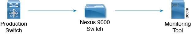
In the Cisco Nexus Data Broker (NDB) fabric, encapsulated traffic from the production environment reaches the span port. Connection between the NDB span port and the delivery port is established by the VXLAN filter. The filter is applied on the received traffic and the filtered traffic is sent out using the delivery (monitor) port to the monitoring tool for other operations.
You can filter the packets based on the offset value, upto 128 bytes in a frame, by using advanced packet filtering with UDF.
Capture the production traffic to get the VNI value and VNI hex value. Consider a VNI value of 334400 (3 bytes) and VNI hex value as 0x51a40.
UDF can match a maximum of two offsets. In this case, VNI has three bytes and we need to match three offsets which is achieved by stacking the UDFs.
Prerequisites
Configure TCAM for UDF under ing-ifacl or if-acl. For implementing advanced filtering, the respective regions must be qualified for UDF.
|
Platform |
UDF Qualifying TCAM Region |
|---|---|
|
Cisco Nexus 9200, Cisco Nexus 9300-EX/9300-FX and Cisco Nexus 9500-EX/9500-FX |
ing-ifacl |
|
Other platforms |
ifacl |
|
UDF Ether Type |
NDB Version |
NX-OS Version |
Platform |
|---|---|---|---|
|
IPv4 |
3.3 |
7.0(3)I5(2) |
Cisco Nexus 9200, Cisco Nexus 9300 |
|
IPv6 |
3.6 |
7.0(3)I6(1) |
Cisco Nexus 93xx EX/FX , Cisco Nexus 95xx EX/FX,Cisco Nexus 92xx |
Guidelines and Limitations
The guidelines and limitations for UDF:
-
UDF is not supported in OpenFlow deployments.
-
UDF is not supported on Cisco Nexus 3000 switches.
-
One UDF can check a maximum of two consecutive bytes.
Workflow for VXLAN Packet Filtering Using UDF
The following table lists the tasks for the workflow. Complete the tasks in the order as indicated in the table.
|
Task |
Description |
Result of the Task (Examples used in the tasks are indicated here) |
|---|---|---|
|
Creates two UDFs. |
Created UDFs - UDF_VXLAN_2bytes and UDF_VXLAN_1byte. |
|
|
Qualifies the UDFs on the switch to reflect in the NDB GUI. |
UDFs are ready in the NDB GUI. |
|
|
Creates a filter. |
Created filter - VXLAN-VNID_UDF_Filter. |
|
|
Configures port for ingress traffic (from the production switch). |
Configured the selected interface as the span port. |
|
|
Configures port for egress traffic (to the monitoring tool). |
Configured the selected interface as delivery port. |
|
|
Establishes connection between the created span port, delivery port and filter. |
Created connection - VXLAN-VNID_UDF_Connection. |
Creating a UDF for VXLAN Offset
Use this procedure to create a UDF.
Use this procedure to create two UDFs, one after the other using the NDB GUI. The second UDF is called the stacking UDF. Two UDFs are created and stacked to filter three consecutive bytes in a packet.
Procedure
| Step 1 |
Navigate to Configuration > UDF Definition. The User Defined Field Definition page is displayed. |
||
| Step 2 |
Click Add UDF. |
||
| Step 3 |
In the Name field, enter the names for UDF-1 and UDF-2. Enter the names as UDF_VXLAN_2bytes and UDF_VXLAN_1byte for UDF-1 and UDF-2 respectively. |
||
| Step 4 |
Select IPv4 from the Type drop-down menu. |
||
| Step 5 |
Select Packet-Start from the Keyword drop-down menu. Selecting Packet-Start enables UDF to start the matching process from the starting of the packet. |
||
| Step 6 |
Enter the Offset value. Enter the offset value as 50 and 52 for UDF-1 and UDF-2, respectively.
|
||
| Step 7 |
Enter the Length. Enter length as 2 and 1 for UDF-1 and UDF-2, respectively. |
||
| Step 8 |
Check the check box under Devices. UDF is created on the selected device (Cisco Nexus 9000 switch). |
||
| Step 9 |
Click Submit UDF. |
What to do next
Use the show running-config command to confirm the UDF configuration on the switch.
Qualifying a UDF
After a UDF is created , it needs to be qualified in the switch. Use this procedure to qualify a UDF for a switch.
Procedure
| Step 1 |
Navigate to Configuration > UDF Definition. The User Defined Field Definition page is displayed. In this page, the created UDFs are displayed with a yellow circle next to the switch name, to indicate that the UDFs are not qualified yet. |
||
| Step 2 |
Check the switch uptime using the show version|inc uptime command. The example below shows that switch uptime is 21 hours and it has not been reloaded for 21 hours. UDFs are pushed to the switch from the NDB controller which implies that UDFs are not programmed in the hardware. |
||
| Step 3 |
Run the copy running-config startup-config command manually in the switch to qualify the UDF.
|
||
| Step 4 |
Check the switch uptime using the show version|inc uptime command. The switch uptime should indicate a value suggesting that the switch was reloaded recently. The example below shows that switch uptime is 3 minutes, confirming that the switch is reloaded and hence the UDFs are qualified. After the UDFs are qualified, they are displayed with a green circle next to the switch name. |
Creating a Filter with UDF
Use this procedure to create a filter using UDF.
Procedure
| Step 1 |
Navigate to Configuration > Filters. The Filters page is displayed. |
| Step 2 |
Click Add Filter. |
| Step 3 |
In the Name field, enter the name of the filter. Enter the filter name as VXLAN-VNID_UDF_Filter. |
| Step 4 |
Click the UDF drop-down menu and select the earlier created UDF, UDF_VXLAN_2bytes. |
| Step 5 |
Enter the values in decimal format in the Value and Mask fields. In the Value field, enter 1306 which is the decimal value for 0x51a. Based on the details provided for the Topology, the offset of the VNI value for 2 bytes is 0x51a. In the Mask field, enter 65535 to match the exact value in the VXLAN packet. 65535 is the decimal value for 0xffff. |
| Step 6 |
Click Add. |
| Step 7 |
For creating a stacking UDF in the same filter, select the other UDF which was created, UDF_VXLAN_1byte. |
| Step 8 |
Enter the values in decimal format in the Value and Mask fields. In the Value field, enter 64 which is the decimal value for 0x40. Based on the details provided for the Topology, the offset of the VNI value for 2 bytes is 0x51a. In the Mask field, enter 255 to match the exact value in the VxLAN packet. 65535 is the decimal value for 0xff. |
| Step 9 |
Click Add. |
| Step 10 |
Click Add Filter. |
Creating a Span Port
Use this procedure to create a span port, which is the ingress port for the VXLAN packet.
Procedure
| Step 1 |
Navigate to Configuration > Port Definitions > Port Configuration. |
| Step 2 |
Click Configure on the port to be configured as the span port. The Configure Ports window is displayed. |
| Step 3 |
Select Edge Port - SPAN from the drop-down menu. |
| Step 4 |
In the Port Description field, enter Span_port. |
| Step 5 |
Enter the VLAN ID as 100. |
| Step 6 |
Click Submit. |
What to do next
Use the show running-config command to check the configurations of the span port.
Creating a Delivery Port
Use this procedure to create a delivery port, which is the egress port for the VXLAN packet (with filter).
Procedure
| Step 1 |
Navigate to Configuration > Port Definitions > Port Configuration. |
| Step 2 |
Click Configure on the port to be configured as the monitor tool port. |
| Step 3 |
Select Add Monitoring Device. The Add Monitoring Device window is displayed. |
| Step 4 |
In the Monitoring Device Name field, enter Tool_port. |
| Step 5 |
Click Submit. |
What to do next
Use the show running-config command to check the configurations of the delivery port.
Creating a Connection with VXLAN UDF Filter
Use this procedure to create a connection with a VXLAN filter.
Procedure
| Step 1 |
Navigate to Configuration > Connections > User Connections. |
| Step 2 |
Click New Connection. The Add Connection window is displayed. |
| Step 3 |
In the Connection Details pane, enter a name for the Connection Name field. Enter the connection name as VXLAN-VNID_UDF_Connection. |
| Step 4 |
In the Filter Details pane, select the created filter from the Allow Filters drop-down menu. |
| Step 5 |
In the Destination Device/ Destination Group Details pane, select the Source and Destination ports. |
| Step 6 |
Click Install Connection to install the connection in the switch. |
What to do next
Use the show running-config command to confirm the UDF configuration on the switch.
Check for the offset values in Hex format (0x51a and 0x40). The values that were entered in decimal format in the NDB GUI are converted to Hex value and this is displayed in the running configuration of the switch.
Validating VXLAN Traffic
Use this procedure to confirm VXLAN packet matching based on VNI value and UDF.
Before you begin
Send VXLAN traffic with VNI value 334400 from the production switch to the span port.
Procedure
| Step 1 |
Check the VXLAN traffic on the span port using show interface type interface counters command. Span port counter is incremented based on the VNI value. |
| Step 2 |
Check the VXLAN traffic on the delivery port using show interface type interface counters command. Delivery port counter is incremented exactly by the same the number of VXLAN packets received at the span port. |
 Feedback