Segment Routing Simulation

By default, WAE Design creates and routes RSVP LSPs. However, you can create Segment Routing (SR) LSPs by changing the LSP Type property to SR. These SR LSPs use autoroute, forwarding adjacencies, and class-based forwarding, just like RSVP LSPs. Once the packet enters the tunnel, the different routing mechanisms determine the path. An RSVP LSP is first established along a path, with each node on the path accepting the reservation request and maintaining the reservation state. In contrast, SR LSPs rely on a segment list that is created at the LSP’s source node (head-end). This segment list, which is stored in the packet (demand), directs the traffic over a series of configured node segments and interface segments. SR LSPs use IP routing (and thus, potentially ECMP) between segments.


Note


WAE Design uses the terms SR LSPs that use segment lists , which contain segment list hops . In Cisco routing terminology, these terms are SR tunnels that use segment ID (SID) lists , which contain SIDs .

This section contains the following topics:

SR LSP Segment Types

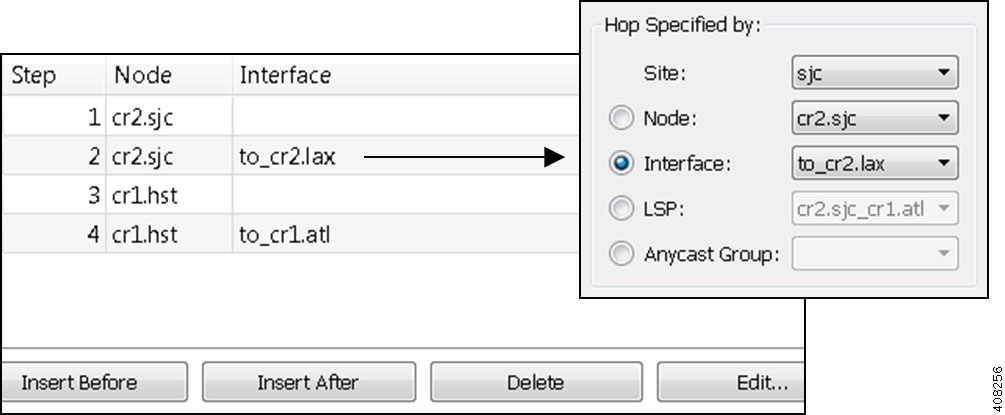
The segment list of an SR LSP contains one or more segment list hops, which can be nodes, interfaces, SR LSPs, or anycast groups.

To view a segment list, right-click an SR LSP and choose Filter to Segment Lists. You can then right-click the segment list and choose Filter to Segment List Hops.


Note


The process of creating and optimizing segment lists and their segment list hops can be automated using the SR-TE Optimization tool. For information, see SR-TE Optimization. You can also create SR LSPs and their hops by optimizing bandwidth. For information, see SR-TE Bandwidth Optimization.

Node Segment List Hops

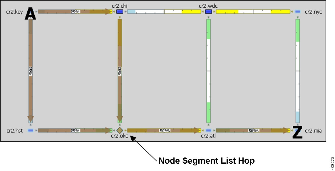
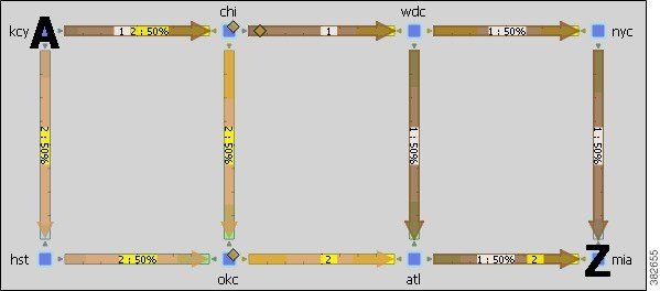
When using node segment list hops, the SR LSP takes the shortest path to the specified node. Example Node Segment List Hop shows an example SR LSP from cr2.kcy node to cr2.mia node using one node segment list hop, which is cr2.okc. Because the IGP metrics are equal, the traffic is routed using ECMP to reach okc.

Figure 1. Example Node Segment List Hop

Interface Segment List Hops

On routers, interfaces can only be used in segment lists if the previous segment list hop is the node containing the interface, or if the interface is the egress of the source node. In WAE Design, there is no restriction that an interface segment list hop be local. There is no requirement that the segment list contain a preceding segment to the node containing the interface.

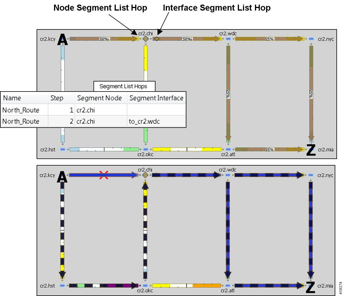
Example Interface Segment List Hop shows an example of an interface segment list hop from cr2.chi to cr2.wdc. To ensure the path reaches cr2.chi (the node the packet must reach to use this interface segment list hop), a node segment list hop is configured first to reach chi. This figure also shows how a demand through an SR LSP reroutes when a node fails. The demand uses IGP to route around the failure and back to the segment, if possible.

Figure 2. Example Interface Segment List Hop

LSP Segment List Hops

SR LSPs can use other SR LSPs as segment list hops, and in turn, these SR LSPs segment list hops can contain other SR LSPs as segment list hops. Two rules apply:

  • The LSP segment list hop must be an SR LSP, not RSVP LSP.

  • An LSP segment list hop cannot reference another SR LSP that directly or indirectly references it. For example, if the segment for SR LSP A contains SR LSP B as a segment list hop, SR LSP B cannot contain SR LSP A as a segment list hop.

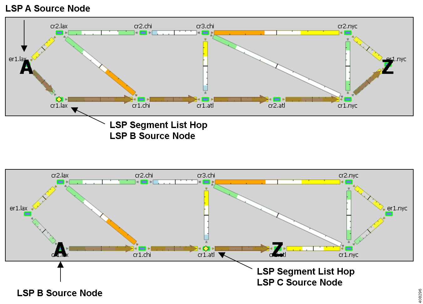
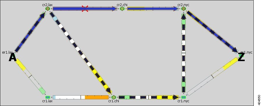
If a selected SR LSP contains an LSP segment list hop that contains yet another LSP segment list hop, only the top-level LSP segment list hop is identified by the yellow diamond icon. The destination of an LSP segment list hop is not identified. For example, Example LSP Segment List Hop shows that LSP A (from er1.lax to er1.nyc) contains an LSP B segment list hop, whose source node is cr1.lax. By deselecting LSP A and then selecting LSP B, you see that LSP B also contains an LSP segment list hop, which is LSP C whose source node is cr1.atl.

Figure 3. Example LSP Segment List Hop

Anycast Group Segment List Hops

An SR LSP routes through the node in an anycast group segment list hop that has the shortest path to it. In case of a tie between multiple nodes in an anycast group, ECMP is applied. This mechanism lets you impose routing restrictions in terms of potential intermediate segment destinations. It also lets the SR LSP choose among the possible next hops (next segment list hops), potentially reducing latency and improving load balancing.

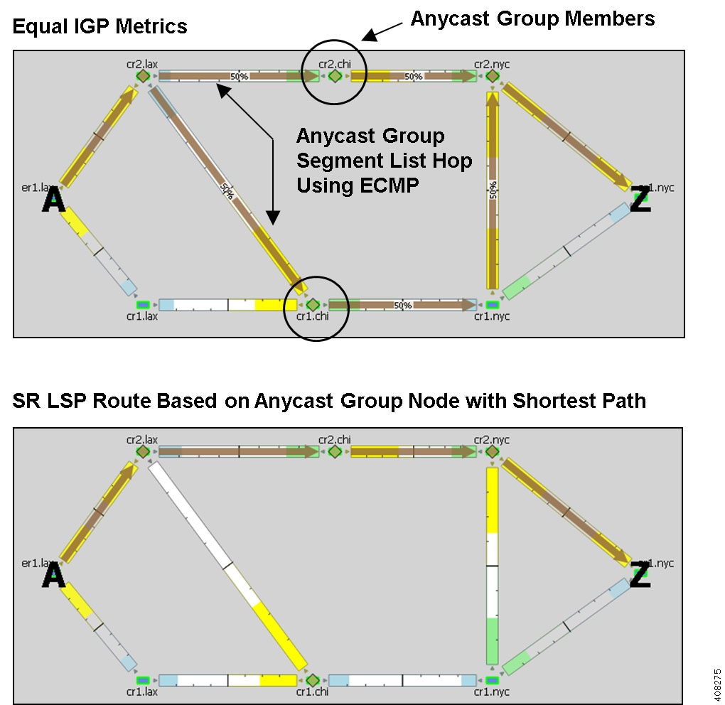
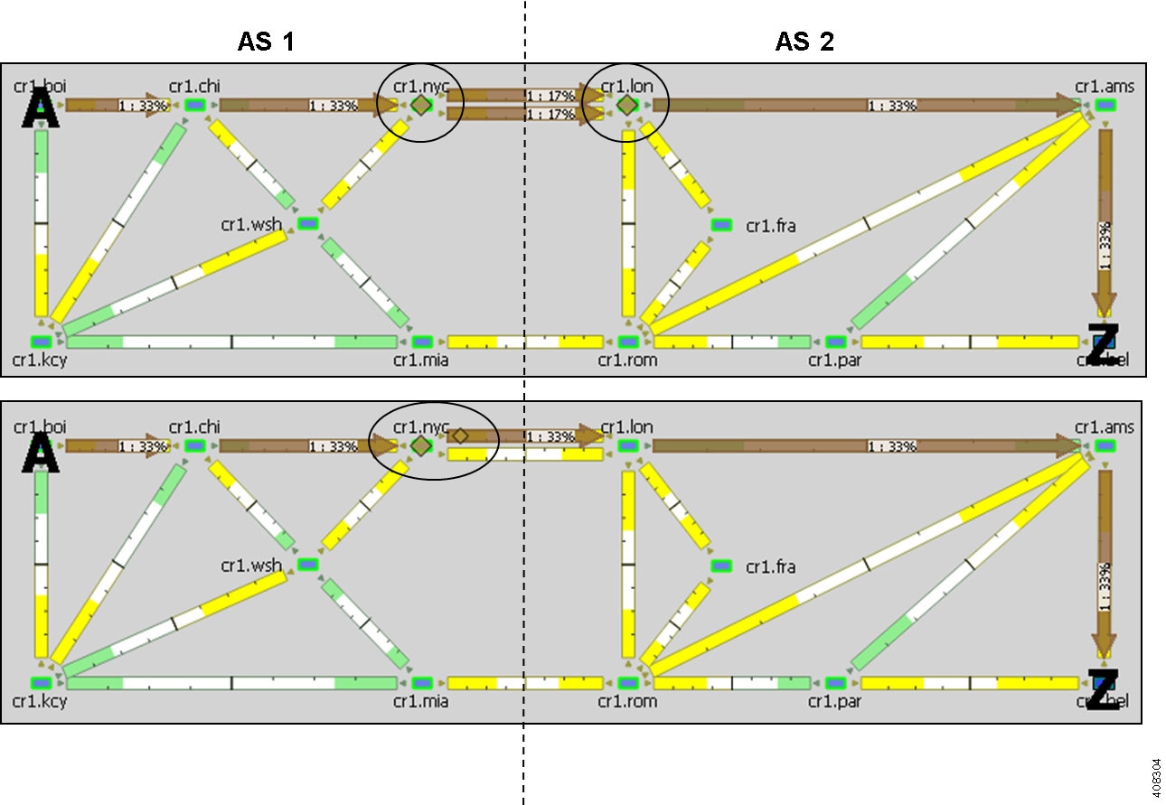
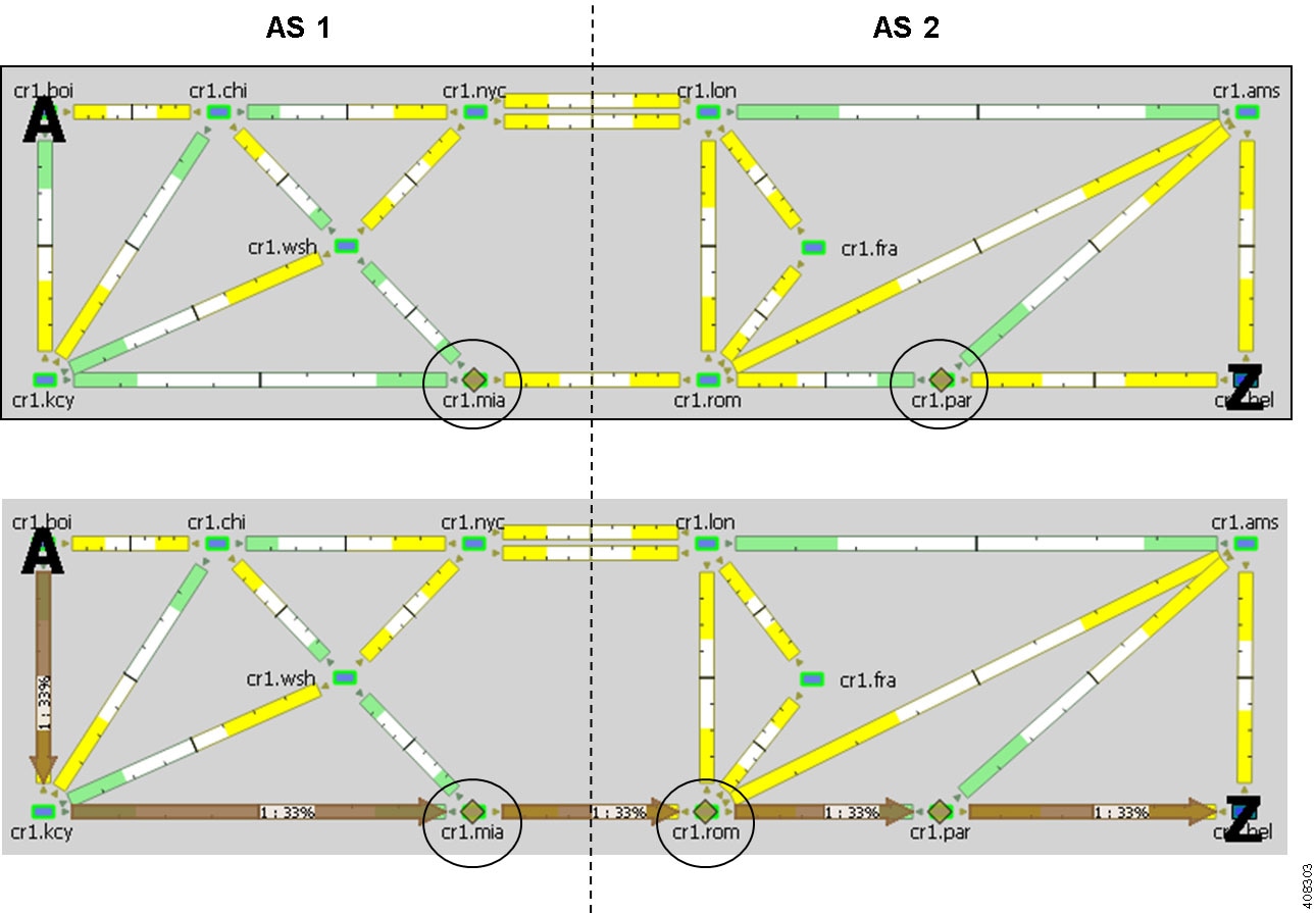
Example Anycast Group Segment List Hop shows an example of anycast group nodes cr2.chi and cr1.chi. In one instance, the IGP metrics to those nodes have equal IGP metrics, so the SR LSP uses ECMP to route through both of them. When the IGP metric increases from cr2.lax to cr1.chi, the SR LSP routes only through cr2.chi because it has the shortest path. However, as Example Anycast Group Rerouting Around Failure shows, if a failure prevents the shortest path from being used, the SR LSP can still route through the anycast group using the next-highest cost path.

Figure 4. Example Anycast Group Segment List Hop
Figure 5. Example Anycast Group Rerouting Around Failure

SR LSP Paths

SR LSPs can have multiple LSP paths, where each LSP path has its own segment list. There is no distinction between standby and non-standby LSP paths for SR LSPs.


Note


If both the SR LSP and its SR LSP paths have segments, the segments on the LSP paths override those on the SR LSP.

Example SR LSP Paths shows an SR LSP from kcy to mia that has a primary and a secondary path. The primary path is configured with a chi node segment list hop and chi-to-wdc interface segment list hop, and the secondary path is configured with a node segment list hop in okc. This can be seen by selecting the LSP paths individually from the LSP Paths table.

Figure 6. Example SR LSP Paths

SR LSP Routing

Table 1. Feature History

Feature

Release Information

Description

Dynamic SR Policy Support

Cisco WAE Release 7.5.0

A new configuration called Dynamic is introduced in the LSP path table. If SR LSP is configured as Dynamic, LSP path is automatically generated with the given metric type. This is applicable for IGP, TE, and Delay metric types.

Assuming the common LSP mechanisms such as autoroute and forwarding adjacencies have determined that a demand will enter an SR LSP, the LSP traffic is routed as follows. If the destination node or segment list hops are not reachable, the SR LSP is not established.


Note


The process of creating final segment list hops can be automated using the Traffic Demand Modeling tool.
  • If the SR LSP does not have a segment list, the demand is routed via IGP to the destination node.

    If the SR LSP has a segment list, the demand is routed using the segment list hops within the segment list in the sequential order in which they appear.

  • If it is using a node segment list hop, the demand takes the shortest path to that node.

    If it is using an interface segment list hop, the demand takes the shortest path of the source node of that interface, and then routes to that interface’s destination node.

    If it is using an anycast group segment list hop, the demand routes through the node with the shortest path. In case of a tie between multiple nodes in an anycast group, the SR LSP uses ECMP to route.

  • If you select both a node and an anycast group containing that node when creating the segment list hop, the node segment has precedence.

  • If the SR LSP contains LSP paths, the demand is routed on the LSP path with the lowest path option for which the demand can be routed from source to destination. Demands for SR LSP paths route in the same manner as described above for SR LSPs.

  • If the SR LSP contains multiple SR Candidate paths, the demand is routed on the LSP path with the highest preference option for which the demand can be routed from source to destination. Demands for SR LSP paths route in the same manner as described above for SR LSPs.

  • If SR LSP Path is configured as 'Dynamic', the LSP path is simulated based on the specified 'Metric Type'. This is applicable for IGP, TE, and Delay metric types. As ECMP is not allowed along the path, interfaces with the lowest IP address are preferred. If there is a segment list configured, the LSP path is not dynamically allocated.

  • If the demand cannot be routed on the segments defined in the SR LSP or its LSP paths (for example, because of a failure in a node segment list hop), the demand is routed to the destination using the IGP shortest path.

  • If a hop (nodes, interfaces, LSPs, or anycast groups) contains a segment ID (SID), the segment list hop inherits that SID.

Inter-AS SR LSP Routing

SR LSPs with source and destination nodes in different ASes can route provided the following hop configurations exist:

  • There is a node segment list hop on the border of the AS that the LSP is exiting. This node is the exit node.

  • One of these hops exists:

    • A node segment list hop exists on the first node traversed in another AS. This node is the entry node. If there are multiple peering interfaces, their metrics determine which one the LSP uses.

    • An interface segment list hop connects the exit node of one AS to an entry node in another AS.

    Segment List Hops Define Exit and Entry Points Across AS shows an example of each of the preceding configurations. Both networks show two ASes, and both show a node segment list hop on cr1.nyc, which is the node from which the LSP is exiting AS 1. The top half shows the cr1.lon node, the entry node to AS 2, as the next segment list hop. The lower half shows the cr1.nyc-to-cr1.lon interface, which connects the exit node in AS 1 to an entry node in AS 2, as the next segment list hop.

    Without these conditions being met, SR LSPs cannot route across AS boundaries. For example, Inter-AS SR LSP Routing Requires Correct AS Exit and Entry Hops shows an SR LSP with the proper node segment list hop set on cr1.mia (exit node of AS 1), but it does not route because the next segment list hop (cr1.par) is not the first node in AS 2 that this LSP would traverse. By adding a node segment list hop on cr1.rom, the SR LSP can route across the ASes.

Using demands with inter-AS SR LSPs requires that two conditions be met:

  • The demand must be private to the SR LSP. For information on creating private LSPs, see MPLS Simulation.

  • The demand must have the same source and destination as the SR LSP.

    Figure 7. Segment List Hops Define Exit and Entry Points Across AS
    Figure 8. Inter-AS SR LSP Routing Requires Correct AS Exit and Entry Hops

Creating SR LSPs and Their LSP Paths

SR LSPs and mesh SR LSPs are created the same way RSVP-TE LSPs are created. The difference is that you must set the Type property to SR.

The SR LSP has a color property which is a 32-bit numerical value.

Once created, the next step is to either create the segment list or create LSP paths and their segment lists.

Likewise, LSP paths are created in the same way as RSVP-TE LSP paths. Because you are creating them from SR LSPs, you can edit the properties Path Option and Active. Set the property Protocol Origin to identify the component or protocol that originates the SR LSP path. Choose from Local, PCE Initiated, and BGP Initiated.

For information on creating LSPs and LSP paths, see MPLS Simulation.

Creating Segment Lists

You can create segment lists and destination segment lists hops automatically using the Explicit LSP Paths initializer. This initializer creates as few segment list node and interface hops as possible to route according to the options selected. The destination node of the LSP is added as the final segment list hop unless the final hop is a segment list interface hop that terminates on the destination node.

Procedure


Step 1

Choose Insert > LSPs > Segment List, or right-click in the plot and choose New > LSPs > Segment List.

Step 2

Add the segment list hops in the order in which they are to be followed.

  • To add a new segment list hop, select an existing hop (if applicable), and then click Insert Before or Insert After to determine where the new hop goes sequentially. Go to Step 2.

  • To edit an existing segment list hop, select it from the list and then click Edit. Go to Step 2.

  • To delete an existing segment list hop, select it from the list, click Delete, and then click OK. You need not continue.

Step 3

To continue creating or editing a segment, use the following options and then click OK. As needed, choose the site, node, interface, or anycast group.

Note

 
Interface segment list hops must be the egress interface of a node segment list hop.
  • If the node or source node (for interfaces and LSPs) is within a site, first choose the site.

  • For node segment list hops, do not choose an interface.

  • For interfaces and LSPs segment list hops, first choose the source node.

  • For anycast group segment list hops, do not choose a site, node, or interface.

After the segment list is created, another way to manage segments is to double-click one from the Segment List Hops table. From there you can change the site, node, and interface, but not the sequence.


Creating Anycast Groups

Procedure


Step 1

Choose Insert > Anycast Group, or right-click in the plot and choose New > Anycast Group.

Step 2

Enter a unique name to identify the anycast group.

Step 3

For each node you want to include in or exclude from the anycast group, check the T (true) or F (false) check box. Then click OK.


Creating SIDs

Table 2. Feature History

Feature

Release Information

Description

SRv6 and Flex Algo Support

Cisco WAE Release 7.5.0

Cisco WAE Release 7.6.0

Cisco WAE Design is enhanced to support SRv6 topology information including SRv6 Node and SRv6 Interface SIDs.

WAE Design model file schema is also enhanced to include Flex Algo information.

Use the following procedures to create new SIDs.

Creating Node SID

Procedure


Step 1

Choose Insert > SIDs > Node SID.

Step 2

In the Node SIDs tab, select values for Site, Node and Type from the drop-down.

Step 3

Enter values for SID and SR Algorithm.

Step 4

Use the check box to select Protected, IPv6 as necessary.

Step 5

Click OK.

Use the Loopbacks tab to edit the Node SIDs.


Creating SRv6 Node SID

Procedure


Step 1

Choose Insert > SIDs > SRv6 Node SID.

Step 2

In the SRv6 Node SIDs tab, select values for Site, and Node from the drop-down.

Step 3

Enter values for SID and SR Algorithm.

Step 4

Use the check box to select Protected as necessary.

Step 5

Click OK.

Use the Loopbacks tab to edit the SRv6 Node SIDs.


Creating Interface SID

Procedure


Step 1

Choose Insert > SIDs > Interface SID.

Step 2

Select values for Site, Node, Interface and Type from the drop-down.

Step 3

Enter values for SID.

Step 4

Use the check box to select Protected, IPv6 as necessary.

Step 5

Click OK.


Creating SRv6 Interface SID

Procedure


Step 1

Choose Insert > SIDs > SRv6 Interface SID.

Step 2

Select values for Site, Node, and Interface from the drop-down.

Step 3

Enter values for SID and SR Algorithm.

Step 4

Use the check box to select Protected as necessary.

Step 5

Click OK.


Creating Flex Algorithm

Procedure


Step 1

Choose Insert > SIDs > Flex Algorithm.

Step 2

In the Basic tab, enter value for SR Algorithm.

Step 3

Select values for IGP Process ID, OSPF Area, ISIS Level and Metric Type from the drop-down.

Step 4

Click OK.

Use the Flex Algo Affinities tab to edit the Flex Algorithm.


SR-TE Protection

If the network contains a configurable topology-independent loop-free alternate (TI-LFA), you can simulate SR-TE tunnels before and after convergence.


Note


To see the simulation before convergence, you must be in Fast Reroute mode (choose Edit > Network Options; in the Simulation Convergence Mode area, choose Fast Reroute). In IGP and LSP Reconvergence mode, you can only see the after-convergence routes.

SR-TE Tunnel Simulation Before Convergence

For each SR tunnel in a plan file, and for each SID in the path, WAE Design determines the no-failure route.

In a normal path state , WAE Design determines the no-failure route from segment list hop to segment list hop. Between segment list hops, WAE Design follows the IGP shortest path to the next segment list hop. At each interface along the path, if the connected circuit is down, WAE Design determines whether the next segment list hop is an interface or a node, and whether the SR tunnel is routable.

  • If SR FRR is enabled for the interface in the Interfaces table, WAE Design configures the protect path state:

    • WAE Design derives the post-convergence path from the local node to the next SID hop with the subject circuit removed from the topology.

    • The next SID hop depends on the SID hop type. For an interface SID, the next hop is the remote node of that interface. For a node SID, the next hop is that node.

    • WAE Design follows the derived after-convergence path hop by hop until it reaches the next SID hop. (If a failure occurs along the way, the SR FRR and the SR LSP do not route.)

    • When WAE Design reaches the next SID hop, it returns to the normal path state and resumes following the no-fail path to the SID hop.

  • If SR FRR is not enabled for the interface in the Interfaces table, the SR tunnel does not route.

SR-TE Tunnel Simulation After Convergence

WAE Design routes to each segment list hop through the IGP shortest path under all failure conditions.


Note


An SR LSP might be routable before convergence through a TI-LFA, but unroutable after convergence.

Constraints

  • In the Interfaces table, if SR FRR Enabled is T (true) for a given interface, all SR LSPs with a node or interface SID as the next hop are protected over that interface. If the SRR FRR Enabled is F (false), all SR LSP SIDs are unprotected over that interface.

  • Protected versus unprotected adjacency SIDs are not supported. (All adjacency SIDs are considered protected.)

  • WAE Design does not impose a limit on the TI-LFA path’s label stack depth.

  • WAE Design does not explicitly derive P and Q nodes, but instead derives a protect path that aligns with the after-convergence shortest path from the PLR to the next segment list hop.

  • If any part of the TI-LFA path encounters a failure before reaching the next segment list hop, the TI-LFA path fails and the SR LSP does not route.