What Is Inventory Management?
Managing inventory involves maintaining a record of all of devices installed in the network to support the provisioning of services. It also includes collecting information about the device name, type, operational status, IP address, and so on.
Inventory management is one of the fundamental network management functions. When forecasting service growth or even attempting to provision a new service, it is necessary to know the current network inventory. Can the existing inventory support the forecast growth or new service requests, or must additional equipment be ordered and installed onsite? Can your hardware support a new software release? You will need to check the type and revision of hardware to determine the answer. Has a recall been issued by the vendor for a certain hardware revision of a board? Are you affected? You will need to check the inventory again.
Prime Central can quickly capture, display, and store an inventory of the devices in your network. Prime Central remains automatically synchronized with changes relating to inventory that might occur in the network. All inventory information is stored in the Prime Central database and is available at any time.
Prime Central provides different levels of inventory reports:
-
A complete list of all devices in the network. See Retrieving Common Inventory Data.
-
A detailed list of slots, subslots, cards, and modules installed on the devices. See Retrieving Physical Inventory Data.
Common Inventory Portlet
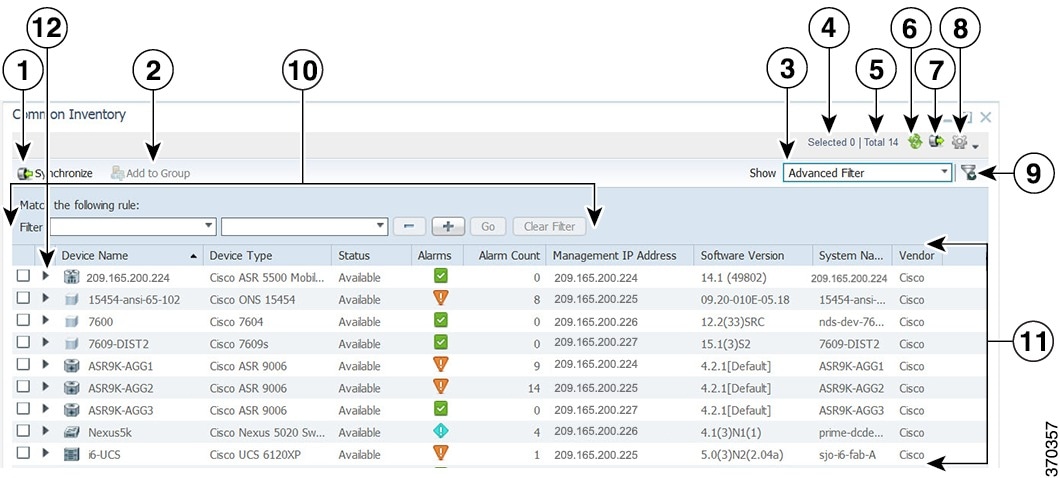
The following figure shows the Common Inventory portlet, where you can view and manage the devices. Device inventory retrieval involves retrieving device and node information from Prime Network, Prime Optical, and Prime Performance Manager.
The Common Inventory portlet does not display device information for Prime Provisioning.
|
1 |
Synchronize icon |
7 |
Export icon |
|
2 |
Add to Group icon |
8 |
Settings icon |
|
3 |
Show drop-down list |
9 |
Filter icon |
|
4 |
Number of selected table rows |
10 |
Filter parameters area |
|
5 |
Total table rows |
11 |
Properties pane |
|
6 |
Refresh icon, with last updated time stamp |
12 |
Expand icon |
Retrieving Common Inventory Data
Procedure
| Step 1 |
From the Prime Central menu, choose . The Common Inventory portlet opens. For a description of the information provided here, see Common Inventory Properties Pane.
|
||
| Step 2 |
(Optional) Use the Filter icon to view only those devices that are of interest to you. See Filtering and Searching. |
Common Inventory Properties Pane
The following table describes the information provided in the properties pane of the Common Inventory portlet for the devices in your network.
|
Field |
Description |
||
|---|---|---|---|
|
ID |
Numerical identifier assigned to the device. By default, this field is not displayed. For instructions on how to enable it, see Adding or Removing Columns in a Portlet. |
||
|
Device Name |
Icon representing the device, followed by the device name. When the same device is managed by multiple instances of Prime Network, the device name must be unique across all the instances of Prime Network.
|
||
|
Device Type |
Type of device.
|
||
|
Status |
Communication state of the device:
|
||
|
Alarms |
Highest severity alarm on the selected device.
|
||
|
Alarm Count |
Total number of alarms on the selected device. |
||
|
Management IP Address |
IPv4 or IPv6 address of the selected device.
|
||
|
Software Version |
Version of software that is running on the selected device. |
||
|
System Name |
System name or hostname of the selected device, as defined in the device’s MIB. |
||
|
Vendor |
Device vendor name. |
Synchronizing Inventory Data
Administrators can perform an on-demand synchronization of user device scopes and inventory.
Procedure
| Step 1 |
From the Prime Central menu, choose . The Common Inventory portlet opens. |
||
| Step 2 |
Click the Synchronize icon.
|
||
| Step 3 |
In the Synchronize dialog box, do the following:
|
||
| Step 4 |
In the Common Inventory portlet, click the Refresh icon. The synchronized data is displayed.
|
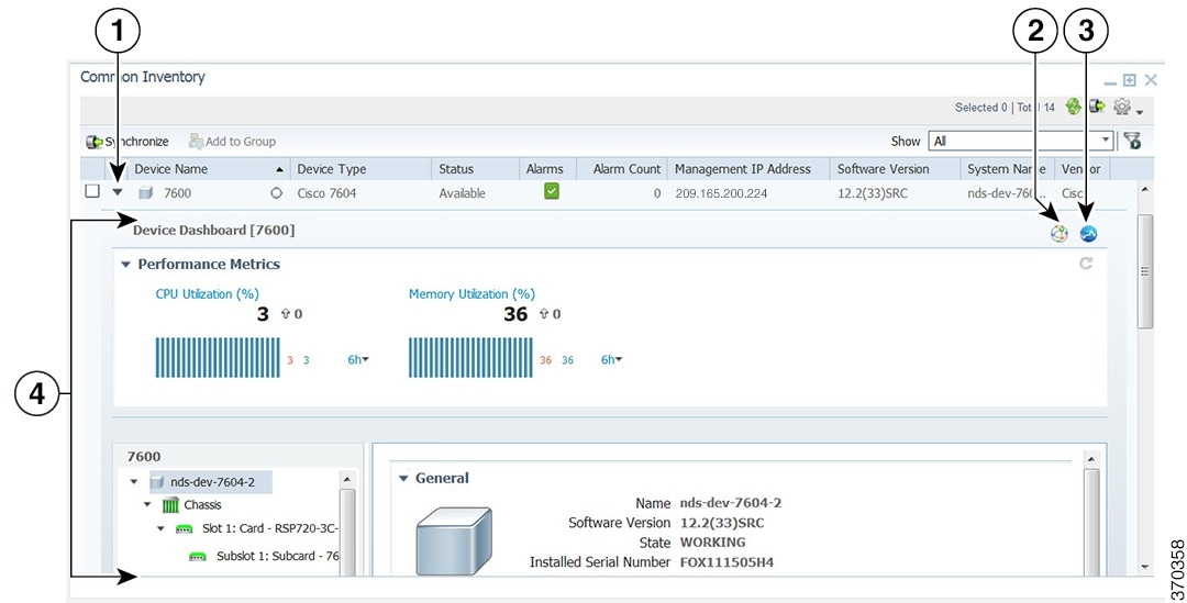
Retrieving Physical Inventory Data
Physical inventory retrieval involves retrieving information about tangible device and node assets, such as chassis, shelf, module, and port information.
Procedure
| Step 1 |
From the Prime Central menu, choose . The Common Inventory portlet opens. |
||||||||||
| Step 2 |
To the left of the device name, click the Expand icon to view a detailed dashboard for that device (see the following figure). |
||||||||||
| Step 3 |
Expand the chassis to view the physical inventory of the subtending equipment: blades, slots, subslots, cards, and so on.
|
Regular Device Attributes for Equipment Holders and Equipment
The following table lists the regular device attributes for equipment holders and equipment.
|
Equipment Holder Attributes |
Equipment Attributes |
|---|---|
|
Operational Status |
Description |
|
Hardware Type |
Installed Serial Number |
|
Model Type |
Installed Version |
|
Location |
Protection Role |
|
— |
Protection Scheme State |
|
— |
Resource Fulfillment State |
|
— |
Last Modified Time |
Retrieving Service Inventory Data
Service Inventory retrieval involves retrieving information on services running on the selected device. All the services in Service Inventory are grouped according to Context.
Procedure
| Step 1 |
From the Prime Central menu, choose Inventory > Common Inventory > Devices. |
| Step 2 |
To the left of the device name, click the Expand icon to view the detailed dashboard for that device (see the following figure) |
| Step 3 |
In the SI Device panel, click on the required context under Service Inventory. |
| Step 4 |
In the SI Device panel, expand the required context, to view the services grouped under it. |
| Step 5 |
Click on the required service, to view the inventory details in the right side panel: Service Name, Service Type, Resource State and Last Modified Time. 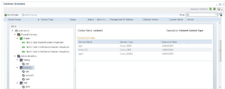 |
Cross-Launching an Application to Retrieve Inventory Details
From Prime Central, you can cross-launch Prime Network, Prime Optical, or Prime Performance Manager and retrieve detailed inventory information. Use the application to retrieve logical inventory information; for example, information about logical resources used for service activation.
 Note |
|
Procedure
| Step 1 |
From the Prime Central menu, choose . The Common Inventory portlet opens. |
||||||||
| Step 2 |
To the left of the device name, click the Expand icon for the desired application. |
||||||||
| Step 3 |
In the top-right corner of the device dashboard, click the source icon to cross-launch the application. The following table lists the source icons.
|
Performing a Contextual Cross-Launch to the Data Center Hypervisor Pane
While managing the devices in your network, you can perform a contextual cross-launch to the Data Center's Hypervisor pane and view detailed inventory information for a particular hypervisor.
Procedure
| Step 1 |
From the Prime Central menu, choose . The Common Inventory portlet opens. |
| Step 2 |
To the left of the device on which a particular hypervisor resides, click the Expand icon to open the corresponding dashboard. |
| Step 3 |
From the object selector pane, click the name of the blade server associated with the hypervisor. The right-hand pane updates, displaying information for that blade server. |
| Step 4 |
From the Equipment section, click the hypervisor's link. The Hypervisor pane (Assure > Data Center > Compute > Hypervisor) opens, displaying detailed inventory information for the selected hypervisor. |
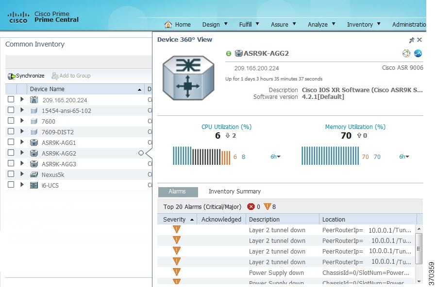
Device Information in the Device 360° View
In the Common Inventory portlet, you can access additional information for a particular device by launching its 360° view . To do so, place your cursor over the device's table entry and then click the radio button in the Device Name column.
The Device 360° view (see the following figure) shows device-specific alarms from the Prime Central Fault Management database, as well as performance charts from Prime Performance Manager.
Click the Alarms or Inventory Summary tabs to see detailed alarm and inventory information. (The features that appear in the Device 360° view differ depending on the device type.)
From the Device 360° view, you can cross-launch the application that manages the device and retrieve detailed inventory information. In the top-right corner, click the source icon listed in the Source Icons table.
Access Points Portlet
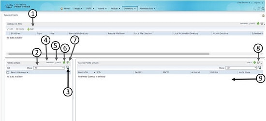
|
1 |
Configures ACS details panel |
|
2 |
Show drop-down list |
|
3 |
Filter icon |
|
4 |
Number of selected table rows |
|
5 |
Total table rows |
|
6 |
Refresh icon with last updated time stamp |
|
7 |
Export icon |
|
8 |
Settings icon |
|
9 |
Properties pane |
Access Points Details Panel
The following table describes different field information in Access Point Details panel and other Access Points related information.
Example: EID, Femto-GW, Latitude, Longitude, Class of Service, Manufacturer, DNB List.
|
Field |
Description |
||
|---|---|---|---|
| Femto-GW |
Used to denote both the HNB gateway and HeNB Gateway that manages different access points. |
||
| EID |
Numerical identifier assigned to the Access point. |
||
|
SecGW |
Used to secure backhaul traffic between the Radio Access Network (RAN) and the operator core network. |
||
|
RNCID |
Radio Network Controller ID. RNC is responsible for controlling the Node BS that are connected to it. |
||
|
Expected latitude |
Latitude where the Access Point is located. |
||
|
Expected Longitude |
Longitude where the Access Point is located. |
||
|
DNB list |
List of the Access Point neighbors. |
||
|
RF Transmitter State |
|
||
|
Model Name |
Model of the Access Point. |
||
|
Software Version |
Version of software that is running on the selected device. |
Note |
You can add different columns in Access Points portlet, through the Settings button at the top right corner. |
Navigating to Access Points Portlet
-
Inventory Menu
-
Add Portlet button
Navigating through Inventory Menu
Procedure
| Step 1 |
From the Prime Central menu, choose Inventory > Common Inventory > Access Points.
|
| Step 2 |
From the Femto Gateways panel, select the required Femto Gateway or select all. |
| Step 3 |
Click the '>>' button beside the Show option and click Get button. |
Navigating through Add Portlet button
Procedure
| Step 1 |
From the top right corner of the Prime Central portlet, under the logout button, click the Add Portlets button. |
| Step 2 |
Choose Cisco Prime > Access Points> Add. |
Configuring Access Points
To view the list of access points available in Access Point portlet, operator should initially provide the configuration details of either RMS/ Spiderweb or Both the servers. You can add, edit or delete RMS or Spiderweb details from the Configured ACS details panel. For more information about the csv file format and its configuration information, see the Setting up the getDeviceData Cron section.
Note |
After saving the configuration from Configuration GUI, the configuration data is stored and scheduler is triggered based on the value of Scheduler Frequency time. If Scheduler Frequency time or any other value needs modification, operator needs to update and save the respective configuration fields. The scheduler will be re-triggered at the Scheduled Time. |
Procedure
| Step 1 |
From the Prime Central menu, choose Inventory > Common Inventory >Access Points. The Access Points portlet appears. 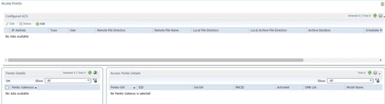 |
||||||||||||||||||||||||||||||||||
| Step 2 |
In the Access Points Portlet, on the Configured ACS details panel, click Add to add RMS and Spiderweb server details. The Access Points - Configuration window appears. 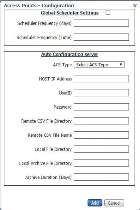
|
||||||||||||||||||||||||||||||||||
| Step 3 |
Click Add to add the configuration details of the access points. |
||||||||||||||||||||||||||||||||||
| Step 4 |
In the Access Points Portlet, to edit the RMS or Spiderweb server detail, select a RMS or Spiderweb server, and then click Edit. The Edit dialog box appears. Enter new values. By default, the Global Scheduler Settings, ACS Type and Host IP Address fields will be disabled. To modify the scheduler Settings again, check the Global Scheduler Settings check box. |
||||||||||||||||||||||||||||||||||
| Step 5 |
Select a RMS or Spiderweb IP address that you want to delete, and then click Delete. Click Yes in the Confirmation dialog box to delete the selected RMs or Spiderweb configuration detail. If you want to delete multiple RMS or Spiderweb IP addresses select multiple instances of RMS or Spiderweb IP Addresses, and then click Delete. |
Access Points Fault Management
Fault Management helps the operator to view and administrate issues that affect the network. Prime Central raises a BAC alarm when the CSV file download from the RMS server to the local server fails, due to reasons such as file does not exist on the RMS Server, insufficient privileges or invalid file path.
Procedure
| Step 1 |
From the Prime Central menu, choose Assure > Prime Central Fault Management. |
| Step 2 |
Click Alarm Browser. |
Exporting Inventory Data
Prime Central allows you to export inventory data to Microsoft Excel. Opening the exported file with any program other than Excel is not recommended.
If you sort or filter the data before exporting it, the exported data is likewise sorted or filtered.
Procedure
| Step 1 |
From the Prime Central menu, choose . |
||
| Step 2 |
In the Common Inventory portlet, click the Export to Excel icon. |
||
| Step 3 |
At the prompt to open or save the Excel file, click Open.
|
||
| Step 4 |
Click Yes at the following prompt: |
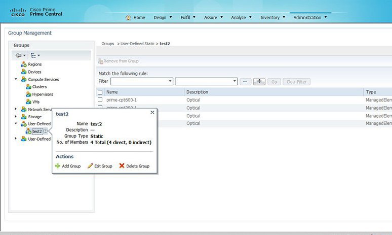
Grouping Network Devices and Services
In the Group Management portlet (see the following figure), you can logically group network devices and services by certain criteria. This allows you to organize network elements as you see fit and quickly determine the members of a particular group when necessary.
To view the Group Management portlet, do one of the following:
-
Choose .
-
Add it to the Prime Central home page. See Adding a Portlet for instructions.
-
User Defined Groups: This group is further divided into Static and User Defined Dynamic Groups.
-
Static Groups: These groups are created under Regions and User Defined-Static Groups. Here the Network Devices are manually populated from Compute, Network, or Storage in the Data Center or from Common Inventory portlet.
-
User Defined Dynamic Groups: In this group, the Network Devices are populated into their respective groups based on certain filters given by the user.
-
-
Prime Central Groups: They are dynamic groups in which the devices are automatically populated by Prime Central, based on the rules configured for those groups, such as Devices, Storage, Compute Services, and Network Services.
See Adding a Group Member for more information.
Note the following:
-
You cannot manually add members to or delete members from a dynamic group.
-
You can only edit or delete user-created groups.
-
Of the groups listed in this portlet, you can only create subgroups for the following:
-
Regions
-
User-Defined Static
-
User-Defined Dynamic
-
 Tip |
To view the information in the Group Management portlet as a Microsoft Excel spreadsheet, click the Export icon in the top-right corner of the portlet. |
Adding a Group
Procedure
| Step 1 |
In the Group Management portlet, open the popup for the relevant parent group and click Add Group. If this option is not available, you cannot create a group within the selected parent group. |
| Step 2 |
In the Add Group dialog box: |
| Step 3 |
Click Save. |
Configuring Group Rules
When configuring a new dynamic group in the Group Management portlet, you need to specify the rules Prime Central will use to populate the group.
Procedure
| Step 1 |
In the Group Rules field of the Add Group dialog box, select the object you want to filter by from the second drop-down list. |
| Step 2 |
From the third drop-down list, select the parameter you want to filter by. The values listed here will vary, depending on the object you selected in Step 1. |
| Step 3 |
From the fourth drop-down list, select a logical operator. |
| Step 4 |
In the text field, enter the value you want to filter by. This value must contain only alphanumeric characters (A-Z, a-z, 0-9) or any of the following special characters: , - . _ @ If you want to configure another rule, proceed to Step 5. Otherwise, skip ahead to Step 8. |
| Step 5 |
Click the + icon. |
| Step 6 |
In the first drop-down list, select whether network elements must meet the conditions of this and any other rules you configured in order to be added to a group. |
| Step 7 |
Repeat Steps 1 through 4. |
| Step 8 |
Click Save. |
Editing a Group
Procedure
| Step 1 |
In the Group Management portlet, open the popup for the relevant group and click Edit Group. If this option is not available, you cannot edit the selected group. |
| Step 2 |
In the Edit Group dialog box, modify the group's name and description. The group's name must contain only alphanumeric characters (A-Z, a-z, 0-9) or any of the following special characters: , - . _ @ |
| Step 3 |
Click Save. |
Deleting a Group
Procedure
| Step 1 |
In the Group Management portlet, open the popup for the relevant group and click Delete Group. If this option is not available, you cannot delete the selected group. |
| Step 2 |
Click Yes to confirm deletion of the group. |
Adding a Group Member
Procedure
| Step 1 |
Do one of the following:
|
| Step 2 |
Do one of the following:
|
| Step 3 |
Check the check box for the device or service that you want to add and click Add to Group. |
| Step 4 |
In the Select Group to Add window, select the appropriate group and click Add. A message indicates that the member was successfully added. |
| Step 5 |
In the Group Management portlet, click the Refresh icon. The new group member is displayed. |
Removing a Group Member
Procedure
| Step 1 |
In the Group Management portlet, navigate to the appropriate group. |
| Step 2 |
Check the check box for the group member that you want to remove and click Remove from Group. |
| Step 3 |
Click Yes to confirm deletion of the group member. |
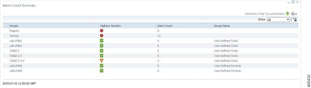
Monitoring Alarm Counts for Grouped Devices
In Alarms Count Summary portlet (see the following figure), you can view total count of alarms for each group defined in Group Management portlet. This enables you to have a consolidated view of total number of faults with their highest severity on network elements of a particular group. To view Alarms Count Summary portlet, add it to the Prime Central home page. See Adding a Portlet for more information on adding a portlet.
In Alarms Count Summary portlet, all User Defined sub-groups are defined in the same level unlike the tree structure in Group Management portlet to enable quick filtering of all subgroups.
You can add devices to User Defined Static Groups manually from Compute, Network, or Storage in the Data Center or from Common Inventory portlet. See Adding a Group Member for more information on adding members to groups. Once the devices are added to a group, their corresponding alarms count along with their highest severity is displayed in the portlet. Alarms Count Summary portlet will update automatically after every 25 seconds, or click refresh button to update the results in the portlet.
 Feedback