- Table Of Content
- Introducing the Cisco Prime NAM 2404 Appliance
- Installing the Cisco Prime NAM 2404 Appliance
- Configuring the Cisco Prime NAM 2404 Appliance
- Installing and Configuring External Storage
- Maintaining the Cisco Prime NAM 2404 Appliance
- Upgrading NAM Software
- Troubleshooting
- Safety Guidelines
- Specifications for the 2404 appliance
- Site Log
- Helper Utility
Cisco Prime Network Analysis Module (NAM) 2404 Appliance Installation and Configuration Guide
Bias-Free Language
The documentation set for this product strives to use bias-free language. For the purposes of this documentation set, bias-free is defined as language that does not imply discrimination based on age, disability, gender, racial identity, ethnic identity, sexual orientation, socioeconomic status, and intersectionality. Exceptions may be present in the documentation due to language that is hardcoded in the user interfaces of the product software, language used based on RFP documentation, or language that is used by a referenced third-party product. Learn more about how Cisco is using Inclusive Language.
- Updated:
- August 30, 2012
Chapter: Maintaining the Cisco Prime NAM 2404 Appliance
Maintaining the Cisco Prime NAM 2404 Appliance
This chapter provides instructions for maintaining your Cisco Prime NAM 2404 appliance.
These instructions are intended for technicians who are experienced with installing, replacing, and removing the hardware components from electronic devices and are familiar with the Cisco Prime NAM 2404 appliances. Additionally, site planners, network administrators, and facility maintenance personnel might also find this chapter helpful.
General Maintenance Guidelines
For information about general maintenance tasks, see the Preparing the Site section in the Cisco UCS Site Preparation Guide.
Reading the LEDs
There are several LEDs on a Cisco Prime NAM 2404 appliance. LEDs serve the following purposes:
- Indicate that basic power is available to the appliance
- Guide you to a broken adapter card, or to one that has failed its diagnostics
- Give an indication that traffic is flowing through the adapter card to the appliance
The LEDs on the front panel of the Cisco Prime NAM 2404 appliance and corresponding adapter card are aids for determining appliance and adapter performance and operation.
This section describes the location and meaning of LEDs and buttons and includes the following topics:
Cisco Prime NAM 2404 LEDs
These sections describe the location and meaning of the LEDs for the Cisco Prime NAM 2404 appliance.
Reading the Cisco Prime NAM 2404 Front-Panel LEDs
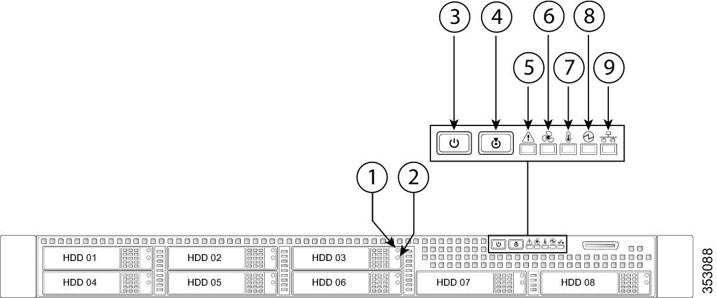
Figure 5-1 shows the front-panel LEDs for the Cisco Prime NAM 2404. Table below defines the LED states.
Figure 5-1 Cisco Prime NAM 2404 Appliance Front View
|
|
Note: NVMe PCIe SSDs drive tray LEDs have slightly different behavior. See Table 5-1 for the LED states. |
|
|
|
|
|
||
|
|
|
||
|
|
|
||
|
|
|
|
Table 5-1 Cisco Prime NAM 2404 Appliance Front Panel LEDs, Definitions of States
|
|
|
|
|---|---|---|
| Note: If your controller is a Cisco UCS RAID SAS 9300-8i or 9300-8e HBA, see the Cisco UCS SAS 9300-8e HBA Considerations Section in the Cisco UCS C220 M4 Server Installation and Service Guide, for differing LED behavior. |
||
|
||
– – – |
||
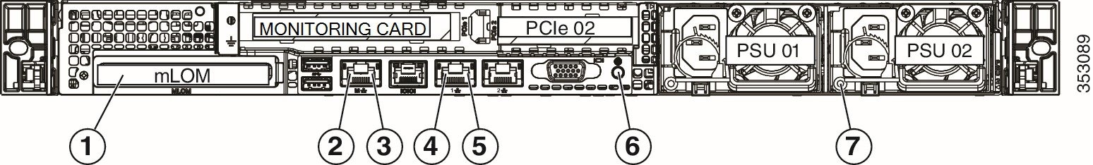
Reading the Cisco Prime NAM 2404 Rear-Panel LEDs
Table 5-2 shows the rear-panel LEDs for the Cisco Prime NAM 2404.
Figure 5-2 Cisco Prime NAM 2404 Appliance Rear View
|
|
Optional mLOM card LEDs |
|
|
|
|
|
||
|
|
|
||
|
|
|
Table 5-2 Cisco Prime NAM 2404 Appliance Rear Panel LEDs, Definitions
Input/Output Ports and Connectors
The Cisco Prime NAM 2404 support the following ports on the rear of the appliance:
- The video connector is not required for normal day-to-day operation of the Cisco Prime NAM appliance.
- The built-in port labeled “M” is the Cisco Integrated Management Controller (CIMC) port.

Note![]() You can either use a single connection on port "1" for both pRIME nam management and CIMC or use port "1" for Cisco Prime NAM management and port "M" for CIMC to connect them to different switches.
You can either use a single connection on port "1" for both pRIME nam management and CIMC or use port "1" for Cisco Prime NAM management and port "M" for CIMC to connect them to different switches.
The Cisco Prime NAM 2404 series appliance use the following connector types:
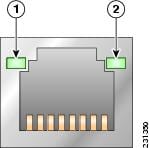
Reading the NIC LEDs
Figure 5-3 shows the NIC 1 LEDs located on the rear of the NAM appliance. These LEDs indicate the connection activity and speed of the NIC ports. Table 5-3 describes the activity and connection speed associated with each LED state.
|
|
|
|
|
|
|---|---|---|---|---|
Reading the AC Power Supply LED
The rear of Cisco Prime NAM 2404 appliances include LEDs that indicate the power status of the AC power supply. (See location 2 in Table 5-2.) Table 5-4 describes the power status associated with the AC power supply LED.
Replacing Appliance Components
Table 5-5 lists the Field Replaceable Units (FRUs) of the Cisco Prime NAM 2404 appliances.
|
|
|
|---|---|
Installing or Removing a UCS PCIe NIC Card
For information about installing or removing a UCS PCIe NIC Card in Cisco Prime NAM 2404 appliances, see the Replacing a PCIe Cardsection in the Cisco UCS C220 Server Installation and Service Guide for NAM 2404 appliance.
Replacing Transceiver Modules
To replace an SFP transceiver module in a Cisco Prime NAM 2404 appliance:
Step 1![]() Locate the new transceiver module you plan to install, remove any protective packaging, and examine it for any signs of damage.
Locate the new transceiver module you plan to install, remove any protective packaging, and examine it for any signs of damage.
Step 2![]() Determine which module you want to replace on the Cisco Prime NAM rear panel.
Determine which module you want to replace on the Cisco Prime NAM rear panel.
Step 3![]() Remove the fiber optical cable from the module to be replaced.
Remove the fiber optical cable from the module to be replaced.
Step 4![]() With your finger, pull the latch down to release the module from its latched position (see Figure 2-2).
With your finger, pull the latch down to release the module from its latched position (see Figure 2-2).
Step 5![]() Using the latch, pull the SFP out of the appliance and place it in a safe location.
Using the latch, pull the SFP out of the appliance and place it in a safe location.
Step 6![]() Insert the new SFP into the slot and slide it in until you feel resistance, then push the SFP harder until you feel (or hear) it click into its socket.
Insert the new SFP into the slot and slide it in until you feel resistance, then push the SFP harder until you feel (or hear) it click into its socket.
Step 7![]() With your finger, pull the latch upwards to lock the SFP into its slot (see Figure 2-3).
With your finger, pull the latch upwards to lock the SFP into its slot (see Figure 2-3).
Step 8![]() Replace the fiber optical cable.
Replace the fiber optical cable.
Note![]() If you use NIC card with RJ45 ports, do not install the transceiver modules.
If you use NIC card with RJ45 ports, do not install the transceiver modules.
Removing and Replacing a Hard Disk Drive
For information about replacing hard disk drives in Cisco Prime NAM 2404 appliances, see the Replacing Hard Drives or Solid State Drives section in the Cisco UCS C220 Server Installation and Service Guide for NAM 2404 appliance.
Customer should not swap any disk with another disk inside the same NAM appliance. This will make the RAID unrecoverable and all data on the RAID will be lost.
Note![]() A single disk failure per RAID can be fixed in the field by replacing the failed disk with an exactly matching disk. You should not swap any disk with another disk inside the same NAM appliance. It makes the RAID unrecoverable and all data on the RAID is lost.
A single disk failure per RAID can be fixed in the field by replacing the failed disk with an exactly matching disk. You should not swap any disk with another disk inside the same NAM appliance. It makes the RAID unrecoverable and all data on the RAID is lost.
Installing or Replacing a Power Supply.
For information about replacing power supplies in Cisco Prime NAM 2404 appliances, see the Replacing Power Suppliers section in the Cisco UCS C220 Server Installation and Service Guide for NAM 2404 appliance.
Removing or Replacing the Cisco Prime NAM 2404 Appliance
Always use the NAM CLI command shutdown to shut down the NAM application.

Warning![]() Power off the unit before you begin. Statement 237
Power off the unit before you begin. Statement 237
Warning![]() Ultimate disposal of this product should be handled according to all national laws and regulations. Statement 1040
Ultimate disposal of this product should be handled according to all national laws and regulations. Statement 1040
To remove a Cisco Prime NAM 2404 appliance from your network, use the NAM CLI command shutdown to shut down the NAM application.
The appliance is in constant communication on your network, which means that when the network notices that the appliance is no longer responding to it, the network stops sending requests to the appliance. This change is transparent to users. If other appliances are attached to the network, the network continues sending requests to the other appliances.
To replace an appliance, remove it from the network. Then, install a new appliance and configure it using the same configuration parameters that you used for the removed appliance.
 Feedback