Change Management
Available Languages
Table Of Contents
Change Management
This chapter contains the following information:
Change management addresses removing and inserting modules in an active chassis. Both of these actions have implications in CGM and need to be handled effectively. You can remove or insert the following modules from a Cisco 12000 GSR chassis:
•
GRPs
•
•
•
•
Removing a Module
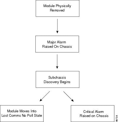
When you remove an existing module from a chassis, CGM detects that the module has been removed by heartbeat polling (which occurs every minute). Once CGM detects the removed module, a major alarm is raised against the chassis object in CGM. The chassis then goes into subchassis discovery mode, to find out exactly what module has been removed. After this process, the removed module is placed in the lost comms no poll state, which causes a critical alarm to be raised against the module. This situation is only rectified when the module is put back into the chassis. When this occurs, heartbeat polling finds the re-inserted module within five minutes' time and alerts the system to its presence. The alarms against the object are now cleared and the module moves into a normal (or perhaps errored) state

Tips
Figure 13-1 CGM Process of Removing a Module
Inserting a New Module
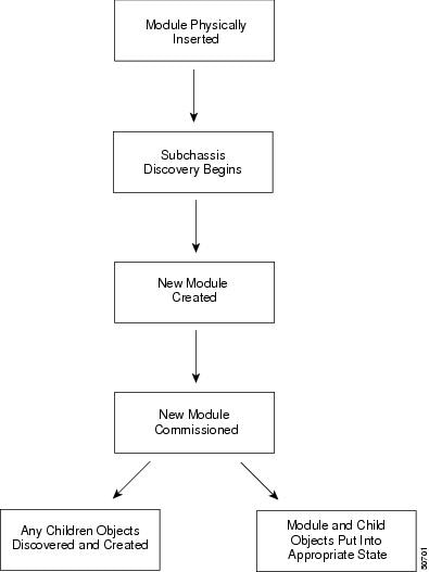
Once you insert a new module into a chassis, it is discovered within five minutes (heartbeat polling occurs every five minutes). That means that the new module might not show up in CGM until after five minutes' time has passed. Once CGM finds the module, the chassis goes into subchassis discovery mode to find out exactly what module has been added. When the new module is discovered, it is added to the system and commissioned. If the module is a line card which has interfaces, the interfaces are discovered during the subchassis discovery process. The commissioning process also determines what state the module should be placed into, which can be the normal, errored, or mismatched state.
Figure 13-2 CGM Process of Inserting a Module
Mismatched State
The mismatched state occurs when a mismatch is found between what is in the hardware and what is deployed in CGM. The mismatched state appears if you insert an incorrect module that does not correspond with the module type that has been pre-deployed in CGM, or, if the pre-deployment for the new module is incorrect. For example: you are expecting an ATM OC-3 line card. So you pre-deploy and pre-configure CGM to prepare for that type of line card. Now, when the line card becomes available and is placed into the chassis, it is not an ATM OC-3 line card, but a POS OC-3 line card. What happens? Once the CGM detects the new line card, it finds a mismatch. The line card gets placed into the mismatch state and a major alarm is raised against the line card.
To rectify a mismatch problem, first you must assess the source of the problem. If the operator was at fault and pre-deployed an incorrect line card, the operator should delete the pre-deployed line card and pre-deploy the correct line card. If the engineer is at fault and inserted the wrong type of line card into the chassis, then the line card should be removed. When you remove a line card, CGM moves that line card into a lost comms no poll state. Insert the correct line card. CGM finds the new line card and downloads the correct pre-deployment and pre-configuration information, then places the line card into a normal state.
 Feedback