- Preface
- Introducing Cisco Network Services Manager
- Understanding Network Services Manager Concepts
- Using the Network Services Manager Northbound API
- Working with Tenants and Network Containers Using the Northbound API
- Using the Network Services Manager UI
- Monitoring Network Status
- Troubleshooting
- Northbound API Parameters
- Glossary
- Index
Cisco Network Services Manager User Guide, 5.0
Bias-Free Language
The documentation set for this product strives to use bias-free language. For the purposes of this documentation set, bias-free is defined as language that does not imply discrimination based on age, disability, gender, racial identity, ethnic identity, sexual orientation, socioeconomic status, and intersectionality. Exceptions may be present in the documentation due to language that is hardcoded in the user interfaces of the product software, language used based on RFP documentation, or language that is used by a referenced third-party product. Learn more about how Cisco is using Inclusive Language.
- Updated:
- November 13, 2012
Chapter: Understanding Network Services Manager Concepts
Understanding Network Services Manager Concepts
This chapter describes and explains the following Network Services Manager concepts:
•![]() Network Services Virtualization
Network Services Virtualization
•![]() Cloud Metamodels and Instances
Cloud Metamodels and Instances
•![]() Tenants and Network Containers
Tenants and Network Containers
Network Services Virtualization
Network Services Manager defines network services virtualization as a model-based definition of:
•![]() A network addressing space.
A network addressing space.
•![]() The physical and virtual resources in the network addressing space.
The physical and virtual resources in the network addressing space.
•![]() The managed services, capabilities, and relationships between the identified network resources.
The managed services, capabilities, and relationships between the identified network resources.
Network Services Manager virtualizes network services by abstracting a logical representation of the physical network that it manages. This logical network is driven by policies that control a user's network access to resources. These policies specify high-level resource sharing and can be created by using the NB API.
Metamodels
A metamodel is an abstraction of a model, similar to the way in which a model is an abstraction of one or more concepts (such as terms, items, or attributes). The difference is that metamodels emphasize the properties of the model itself. In Network Services Manager, a metamodel consists of definitions for specific entities and resources that can exist in a network, and the relationships that exist among these entities and resources. Network Services Manager uses metamodels to control network access and specify resource sharing.
Metamodels are defined in XML-based documents that can be imported, exported, or edited using the Network Services Manager NB API. Metamodels use standard variable and parameter substitutions that enable you to specify the attributes required for your environment.
A primary benefit of metamodels is that, when used with the Network Services Manager northbound API, they enable you to quickly provision and deploy numerous individual network components and resources. As a result, they accelerate and simplify cloud deployments, thereby reducing network operations costs and accelerating service delivery.
Metamodels can be set up during the Network Services Manager installation, or written or adapted by Network Services Manager administrators. Metamodels can be tailored to each environment or situation, enabling you to represent your network in the manner that best suits your environment.
Metamodels offer flexibility by allowing you to determine the parameters that can or must be specified when an entity is created via the Network Services Manager northbound API or the Administration UI.
Metamodel definitions can limit the number of resources you can create with a specific metamodel. These metamodel limits ensure that:
•![]() Extraneous network containers are not created. For example, because a tenant only needs one network container for an external network connection (ENC), the limit is one.
Extraneous network containers are not created. For example, because a tenant only needs one network container for an external network connection (ENC), the limit is one.
•![]() Resources are available to all tenants and cannot be consumed by one tenant alone.
Resources are available to all tenants and cannot be consumed by one tenant alone.
For more information about working with metamodels, see the Using the Network Services Manager NB API.
Policies
Network Services Manager uses policies to manage resources and network access:
•![]() Network access policies define entitlements and access management on a network, and are the primary vehicle for providing VLAN access to the network. Network access can range from a direct connection to a remote location to a private, routed Layer 3 VLAN.
Network access policies define entitlements and access management on a network, and are the primary vehicle for providing VLAN access to the network. Network access can range from a direct connection to a remote location to a private, routed Layer 3 VLAN.
•![]() Business policies give one set of resources access to another set of resources. They are defined in terms of resources, schedule, connection topology, and services. Services can be Network Address Translation (NAT) or firewall services which, in turn, have attributes that define how these resources access each other.
Business policies give one set of resources access to another set of resources. They are defined in terms of resources, schedule, connection topology, and services. Services can be Network Address Translation (NAT) or firewall services which, in turn, have attributes that define how these resources access each other.
You can add or remove resources (including local resources, groups, and VLANs) from business policies, controlling which systems or subnets can communicate with each other. You can also activate or deactivate business policies.
Cloud Metamodels and Instances
A cloud metamodel describes a cloud domain, its properties, and any associated resources, policies, and subordinate metamodels that are necessary to express the particular network requirements of that cloud to Network Services Manager.
When you instantiate a cloud from a metamodel in Network Services Manager, the cloud and all related objects described in the metamodel are created in the business model. Taken as a whole, these business model objects define the resources and capabilities of that particular cloud as specified by the metamodel. The cloud can be further defined with subordinate (child) clouds and resource metamodels that are derived from the parent cloud metamodel.
A cloud instance is the entire collection of business model objects needed to define a cloud from the parent cloud through all subordinate clouds, including any contained resources and relevant policies. In essence, the cloud instance contains all the information that Network Services Manager needs to fully provision a cloud at a given site. One site can support multiple cloud instances.
Cloud instances are independent of any site and the particular device configuration that might be found at a site. A cloud instance can be assigned to any site that has the capabilities necessary to implement the cloud (that is, the devices and roles required by the cloud instance).
Resources
A resource is any item that can be associated in a business policy. Examples of resources are groups, subnets, address pools, zones, and VLANs.
Sites
A site corresponds to a single logical location. In many cases, a Network Services Manager site represents a discrete physical location.
Each site is managed by a controller; one or more Network Services Manager-managed devices; and one or more resources, including subnets or VLANs. Address space for a site is managed by specifying subnet definitions or assigning a VLAN to the site.
Physical Topology
Devices managed at a site are typically interconnected in a physical hierarchy. For example, it is common for a device hierarchy to consist of access switches at the bottom, feeding into one or more levels of higher-bandwidth aggregation switches, and terminating with a very-high-bandwidth distribution layer at the top. Additional devices, such as Layer 3 routers or edge firewalls, might reside above the distribution layer. Additional Layer 2 or Layer 3 service-level devices might exist within the switch hierarchy, providing firewall, load balancing, or QoS capabilities. The term physical topology refers to the description of all devices managed at a site and the manner in which they are interconnected.
Device Stack (Pod)

Note ![]() Network Services Manager uses the word pod to refer to the stack of devices that the controller manages. For clarity, this document uses the term device stack.
Network Services Manager uses the word pod to refer to the stack of devices that the controller manages. For clarity, this document uses the term device stack.
By default, Network Services Manager provides the metamodels and policies that support the device stack shown in Figure 2-1. If your physical topology differs, the metamodels and policies can be modified to support your environment. For more information, contact Cisco Advanced Services or your Cisco representative.
Figure 2-1 Network Services Manager Device Stack
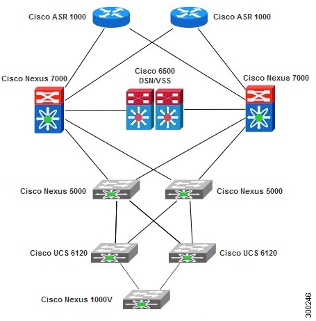
Table 2-1 describes the network elements in the device stack, their roles, and the support that they provide.
Dynamic Topology
In Network Services Manager, dynamic topology refers to the process of retrieving abstract information from a business model, converting that abstract information into device-specific configurations, and implementing those configurations on the appropriate devices. The result is a working version of the network based on:
•![]() Knowledge of the physical and logical topologies of the network.
Knowledge of the physical and logical topologies of the network.
•![]() Knowledge of specific device roles.
Knowledge of specific device roles.
•![]() Data paths constructed through the device stack by Network Services Manager that support the required service chains.
Data paths constructed through the device stack by Network Services Manager that support the required service chains.
When constructing data paths, Network Services Manager evaluates the requested service chain (or policy) against the topology model to determine the best option through the device stack for providing the desired data path. This flexibility in creating data paths removes constraints on the types of service chains allowed, resulting in support for a broader set of service chains.
If required, service chains and network containers can be customized by Cisco Advanced Services to meet specific business needs. For more information, contact Cisco Advanced Services or your Cisco representative.
Domains
A domain is an organizational structure in Network Services Manager that delegates administrative control and provides organizational separation for tenants. A domain can contain all of the business model objects used to manage clouds and enables administrative and management separation for cloud tenants.
Domains contain sites, policies, and so on, providing you with an abstract view of the network in a hierarchy in the Network Services Manager Administration UI. The ROOT domain resides at the top of the hierarchy and contains all other network elements, including tenants and network containers.
Because each object in the system exists within a domain, the entire set of configuration items also has a hierarchical structure.
Tenants and Network Containers
In Network Services Manager, a tenant is a domain that contains business model objects that set up and manipulate one or more logical network containers. For example, a tenant might represent a service provider customer who wants to build a virtual cloud and populate it with virtual machines, or an enterprise customer who wants to allocate different services and resources to various departments.
A tenant network container identifies the device stack that is deployed for a tenant. It is explicitly created by a tenant using Network Services Manager and is defined by a metamodel. One tenant can have multiple tenant network containers that can be combined as needed to meet the needs of the tenant.
When you create a tenant network container, you associate it with a specific device stack, which is a physical stack of devices that is managed by Network Services Manager at a site. A site can be a geographic location, a remote unmanaged environment such as the Internet, or an MPLS remote location.
A tenant network container comprises building blocks called network containers. Network containers can contain zones, VLANs, and ENCs. A zone is a logical collection of network components that share the same security profile. A zone can contain VLANs or ENCs. An ENC allows remote access to a zone via MPLS or a direct connection. A single tenant network container can contain multiple network containers.
Tenant Placement
Network Services Manager uses the concept of blocks in its architecture to enable it to scale the environment as needed. Each block is limited with regard to the number of services (such as VLANs or VRF instances) that can be created within them. However, by locating tenants judiciously, Network Services Manager can optimize the available services.
For example, Network Services Manager can optimize the use of the available services by placing tenants in a way that does not require tenant VLANs to be populated everywhere. If a Cisco UCS device supports 512 VLANs and you populate tenant VLANs on each Cisco UCS device in the stack, you will have fewer than 512 VLANs across the entire stack. However, if you connect the Cisco UCS devices to the stack in a way that constrains a tenant to one block, you can have approximately 512 VLANs per block instead of across the entire stack.
No user interaction is required to take advantage of tenant placement. If no placement information is provided, Network Services Manager uses an algorithm to determine the best arrangement for optimizing the available services.
Redundancy
Network Services Manager automatically configures redundancy for all duplicate devices in the device stack as follows:
•![]() For Layer 3 and above, redundancy is configured by using Hot Standby Redundancy Protocol (HSRP) on the duplicate devices.
For Layer 3 and above, redundancy is configured by using Hot Standby Redundancy Protocol (HSRP) on the duplicate devices.
•![]() For Layer 2 and below, redundancy is supported by using identical configurations on the duplicate devices.
For Layer 2 and below, redundancy is supported by using identical configurations on the duplicate devices.
 Feedback