- Cisco VAMS 1.5 Preface
- Cisco VAMS 1.5 Chapter 1, Overview
- Cisco VAMS 1.5 Chapter 2, Preinstallation
- Cisco VAMS 1.5 Chapter 3, Installation
- Cisco VAMS 1.5 Chapter 4, Uninstallation
- Cisco VAMS 1.5 Chapter 5, Configuration
- Cisco VAMS 1.5 Chapter 6, Troubleshooting
- Cisco VAMS 1.5 Appendix A, Trap Definitions
- Cisco VAMS 1.5 Appendix B, End User License Agreement Supplement
- Cisco VAMS 1.5 Glossary
- Cisco VAMS 1.5 Index
User Guide for Cisco Video Assurance Management Solution 1.5
Bias-Free Language
The documentation set for this product strives to use bias-free language. For the purposes of this documentation set, bias-free is defined as language that does not imply discrimination based on age, disability, gender, racial identity, ethnic identity, sexual orientation, socioeconomic status, and intersectionality. Exceptions may be present in the documentation due to language that is hardcoded in the user interfaces of the product software, language used based on RFP documentation, or language that is used by a referenced third-party product. Learn more about how Cisco is using Inclusive Language.
- Updated:
- June 30, 2008
Chapter: Cisco VAMS 1.5 Chapter 5, Configuration
Configuring the Components of the Cisco Video Assurance Management Solution 1.5
After completing the installation of Cisco VAMS 1.5, you are ready to configure the components of the solution for operation.
The following summary procedure describes how to configure all the components of the
Cisco VAMS 1.5. References to more detailed procedures and documentation are provided.
To configure the components of the Cisco VAMS 1.5:
Step 1 ![]() Ensure that you have met all prerequisites. (See Chapter 2, "Preinstallation." and the "Before You Install" section on page 3-1.)
Ensure that you have met all prerequisites. (See Chapter 2, "Preinstallation." and the "Before You Install" section on page 3-1.)

Note ![]() As an important prerequisite, load all the Cisco devices in the video transport network with IOS software that supports the Cisco VAMS 1.5.
As an important prerequisite, load all the Cisco devices in the video transport network with IOS software that supports the Cisco VAMS 1.5.
Step 2 ![]() In Cisco ANA, create new virtual network elements (VNEs) for the Cisco VAMS 1.5 components. See the "Create VNEs" section.
In Cisco ANA, create new virtual network elements (VNEs) for the Cisco VAMS 1.5 components. See the "Create VNEs" section.
Step 3 ![]() Add the Cisco VAMS 1.5 devices to the Cisco ANA network map. See the "Add Solution Components to the Cisco ANA Network Map" section.
Add the Cisco VAMS 1.5 devices to the Cisco ANA network map. See the "Add Solution Components to the Cisco ANA Network Map" section.
Step 4 ![]() Configure the CMM to set thresholds and forward notifications to the CIC Object Server. Configure the following types of monitoring:
Configure the CMM to set thresholds and forward notifications to the CIC Object Server. Configure the following types of monitoring:
•![]() PPS/BPS Threshold Polling
PPS/BPS Threshold Polling
•![]() Tree Polling
Tree Polling
•![]() Health Checks
Health Checks
•![]() IP Multicast Heartbeat Monitoring
IP Multicast Heartbeat Monitoring
See the "Configure the CMM" section.
Step 5 ![]() Configure the video probes to set thresholds and send events to Cisco ANA. See the "Configure Video Probes" section.
Configure the video probes to set thresholds and send events to Cisco ANA. See the "Configure Video Probes" section.
Note ![]() All components of the Cisco VAMS 1.5 are now operational. The Cisco devices in the video transport network forward notifications to the CMM, which then forwards them to the Cisco ANA. The video probes also forward notifications to the Cisco ANA. The remaining steps of this procedure are optional.
All components of the Cisco VAMS 1.5 are now operational. The Cisco devices in the video transport network forward notifications to the CMM, which then forwards them to the Cisco ANA. The video probes also forward notifications to the Cisco ANA. The remaining steps of this procedure are optional.
Step 6 ![]() (Optional) To manually run the Setup for IPTV activation script, see Run the Setup for IPTV Script.
(Optional) To manually run the Setup for IPTV activation script, see Run the Setup for IPTV Script.
Note ![]() The Setup for IPTV activation script runs automatically at installation time, hourly, and whenever a managed device reloads.
The Setup for IPTV activation script runs automatically at installation time, hourly, and whenever a managed device reloads.
Step 7 ![]() (Optional) To manually run the Cleanup from IPTV activation script, see the "Run the Cleanup from IPTV Script" section.
(Optional) To manually run the Cleanup from IPTV activation script, see the "Run the Cleanup from IPTV Script" section.
Note ![]() Do Step 7 when you want to remove a device from the Cisco VAMS 1.5. The Cleanup from IPTV activation script removes the IPTV extensions.
Do Step 7 when you want to remove a device from the Cisco VAMS 1.5. The Cleanup from IPTV activation script removes the IPTV extensions.
Create VNEs
Use this procedure to create a VNE for each component of the Cisco VAMS 1.5. Table 5-1 lists important values for the VNEs of the Cisco VAMS 1.5. You will need this information when you create the VNEs for the Cisco VAMS.
|
|
|
|
|---|---|---|
Cisco 7600 |
Auto Detect |
Product |
Cisco Catalyst 6500 |
Auto Detect |
Product |
Cisco CRS-1 |
Auto Detect |
Product |
Cisco Catalyst 4948 |
Auto Detect |
Product |
Cisco Multicast Manager |
ICMP |
Product |
Tektronix video probe |
Auto Detect |
Product |
IneoQuest video probe |
Auto Detect |
Product |
Mixed Signals video probe |
ICMP |
Product |
1 Column headings in this table are the names of the fields in the New VNE window, under the General tab. |
To create VNEs for the Cisco VAMS 1.5:
Step 1 ![]() Log in to ANA Manage.
Log in to ANA Manage.
Step 2 ![]() Click the ANA Servers item in the navigation tree (left pane).
Click the ANA Servers item in the navigation tree (left pane).
Step 3 ![]() Click and expand the ANA Gateway item in the navigation tree.
Click and expand the ANA Gateway item in the navigation tree.
Step 4 ![]() Create an Autonomous Virtual Machine (AVM) to contain the VNE objects for the Cisco VAMS 1.5:
Create an Autonomous Virtual Machine (AVM) to contain the VNE objects for the Cisco VAMS 1.5:
a. ![]() Right-click the ANA Gateway in the left pane.
Right-click the ANA Gateway in the left pane.
b. ![]() Choose New AVM from the drop-down menu.
Choose New AVM from the drop-down menu.
c. ![]() Enter an ID number and key.
Enter an ID number and key.
d. ![]() Check the Activate on creation check box and click OK.
Check the Activate on creation check box and click OK.
Note ![]() You may create more than one AVM. For example, you could create one AVM for the Cisco devices and a different AVM for the video probes.
You may create more than one AVM. For example, you could create one AVM for the Cisco devices and a different AVM for the video probes.
Step 5 ![]() Right-click the AVM that contains the IPTV devices, then, choose the New VNE.
Right-click the AVM that contains the IPTV devices, then, choose the New VNE.
Step 6 ![]() Complete these fields in the New VNE window under the General tab:
Complete these fields in the New VNE window under the General tab:
•![]() Name (as ANA identifies it)
Name (as ANA identifies it)
•![]() IP Address
IP Address
•![]() Type (see Table 5-1)
Type (see Table 5-1)
•![]() Scheme (see Table 5-1)
Scheme (see Table 5-1)
•![]() Initial State (Stop or Start)
Initial State (Stop or Start)
Step 7 ![]() Under the SNMP tab, in the SNMP V1/V2 Settings pane, complete these fields:
Under the SNMP tab, in the SNMP V1/V2 Settings pane, complete these fields:
•![]() Community Read
Community Read
•![]() Community Write
Community Write
Step 8 ![]() Enable Telnet or SSH under the Telnet/SSH tab. This information enables discovery of the device.
Enable Telnet or SSH under the Telnet/SSH tab. This information enables discovery of the device.
Step 9 ![]() If the VNE type is ICMP (see Table 5-1), enter a polling rate under the ICMP tab.
If the VNE type is ICMP (see Table 5-1), enter a polling rate under the ICMP tab.
Step 10 ![]() If required, add the VNE to a polling group under the Polling tab.
If required, add the VNE to a polling group under the Polling tab.
Note ![]() The IPTV extensions of the Cisco VAMS 1.5 provide two new polling groups: 30-minute config and 60-minute config. Depending on your polling requirements, choose one of these groups to obtain status, configuration, and system information.
The IPTV extensions of the Cisco VAMS 1.5 provide two new polling groups: 30-minute config and 60-minute config. Depending on your polling requirements, choose one of these groups to obtain status, configuration, and system information.
Step 11 ![]() Enter any other required information in the remaining tabs of the New VNE window and click OK.
Enter any other required information in the remaining tabs of the New VNE window and click OK.
Step 12 ![]() Verify that the new VNE appears in the VNEs table in the right pane of the ANA Manage window.
Verify that the new VNE appears in the VNEs table in the right pane of the ANA Manage window.
Step 13 ![]() To start the new VNE, right-click it in the table and choose Actions > Start.
To start the new VNE, right-click it in the table and choose Actions > Start.
Step 14 ![]() To continue to add new VNEs, repeat this procedure from Step 5.
To continue to add new VNEs, repeat this procedure from Step 5.
Add Solution Components to the Cisco ANA Network Map
Use this procedure to add these components to the Cisco ANA Network Map:
•![]() Cisco 7600 Series router
Cisco 7600 Series router
•![]() Cisco Catalyst 6500 switch
Cisco Catalyst 6500 switch
•![]() Cisco CRS-1
Cisco CRS-1
•![]() Cisco Catalyst 4948 Series switch
Cisco Catalyst 4948 Series switch
•![]() Video probes:
Video probes:
–![]() Bridge Technologies
Bridge Technologies
–![]() IneoQuest
IneoQuest
–![]() Mixed Signals
Mixed Signals
–![]() PixelMetrix
PixelMetrix
–![]() Tektronix
Tektronix
•![]() Cisco Multicast Manager
Cisco Multicast Manager
To add the previous components:
Step 1 ![]() Log in to ANA NetworkVision.
Log in to ANA NetworkVision.
Step 2 ![]() If you have not already, create a new network map:
If you have not already, create a new network map:
File > New Map
Step 3 ![]() To open the device list, choose File > Add Device.
To open the device list, choose File > Add Device.
Step 4 ![]() Choose the device that you want to add to the network map.
Choose the device that you want to add to the network map.
Step 5 ![]() Click Add Device.
Click Add Device.
Step 6 ![]() Verify that the device appears in the network map and links appear between connected devices.
Verify that the device appears in the network map and links appear between connected devices.
Note ![]() If links do not appear and the devices are connected, you can manually create the links as described in the Release Notes for Cisco Active Network Abstraction 3.6 Service Pack 2:
If links do not appear and the devices are connected, you can manually create the links as described in the Release Notes for Cisco Active Network Abstraction 3.6 Service Pack 2:
http://www.cisco.com/en/US/docs/net_mgmt/active_network_abstraction/3.6_sp2/release_notes/rn36_sp2.html
(see defect CSCsi50166).
Step 7 ![]() To add other solution components to the network map, repeat this procedure from Step 3.
To add other solution components to the network map, repeat this procedure from Step 3.
Configure the CMM
To enable notifications and set thresholds for multicast conditions, you must configure the CMM.
This section covers two areas of CMM Configuration:
•![]() General CMM Configuration—This section covers general configuration of CMM.
General CMM Configuration—This section covers general configuration of CMM.
•![]() Setting Up Troubleshooting Configuration for IP Multicast—This section describes configuration of CMM for specific types of monitoring:
Setting Up Troubleshooting Configuration for IP Multicast—This section describes configuration of CMM for specific types of monitoring:
–![]() Configuring BPS/PPS Threshold Monitoring.
Configuring BPS/PPS Threshold Monitoring.
–![]() Configuring IP Multicast Heartbeat Monitoring
Configuring IP Multicast Heartbeat Monitoring
General CMM Configuration
General Configuration tasks for CMM include:
•![]() Discovery of multicast-capable devices in the domain.
Discovery of multicast-capable devices in the domain.
•![]() Global configuration of polling intervals and run times for Layer 2 polling, Designated Router (DR) polling, and polling of Rendezvous Point (RP) status.
Global configuration of polling intervals and run times for Layer 2 polling, Designated Router (DR) polling, and polling of Rendezvous Point (RP) status.
•![]() Configuration of video probes.
Configuration of video probes.
•![]() Configuration of the Channel Mapping database.
Configuration of the Channel Mapping database.
Note ![]() A summary procedure of configuration tasks follows. For complete details about these, and other configuration tasks, see the User Guide for the Cisco Multicast Manager 2.5:
A summary procedure of configuration tasks follows. For complete details about these, and other configuration tasks, see the User Guide for the Cisco Multicast Manager 2.5:
To configure the CMM for the Cisco VAMS 1.5:
Step 1 ![]() In a browser window, open and log in to the CMM.
In a browser window, open and log in to the CMM.
Step 2 ![]() In the Tool drop-down menu, click Administration.
In the Tool drop-down menu, click Administration.
Step 3 ![]() To add a domain, choose Domain Management.
To add a domain, choose Domain Management.
Step 4 ![]() Choose add a new domain. The System Configuration page appears.
Choose add a new domain. The System Configuration page appears.
Step 5 ![]() To discover the devices, choose Discovery > Multicast.
To discover the devices, choose Discovery > Multicast.
Step 6 ![]() To add Video probes, choose Discovery > Add Video Probe.
To add Video probes, choose Discovery > Add Video Probe.
Step 7 ![]() To configure multicast thresholds, choose Multicast Polling Configuration. To activate your changes, click the Start button.
To configure multicast thresholds, choose Multicast Polling Configuration. To activate your changes, click the Start button.
Step 8 ![]() To configure polling intervals and run times, choose Global Polling Configuration. To activate your changes, click the Start button.
To configure polling intervals and run times, choose Global Polling Configuration. To activate your changes, click the Start button.
Step 9 ![]() To configure the Channel Mapping databases, choose Address Management and configure the Channel Map database, the Multiplex Table Database, the Ad Zone database, and the Address database.
To configure the Channel Mapping databases, choose Address Management and configure the Channel Map database, the Multiplex Table Database, the Ad Zone database, and the Address database.
Step 10 ![]() Forward notifications to CIC:
Forward notifications to CIC:
a. ![]() Choose Global Polling Configuration > Domain Trap/Email.
Choose Global Polling Configuration > Domain Trap/Email.
b. ![]() In the right pane, enter the IP address of the CIC Object Server in the Add Trap Receiver field.
In the right pane, enter the IP address of the CIC Object Server in the Add Trap Receiver field.
c. ![]() Click the Add Trap Receiver button. This action adds the CIC Object Server IP address to the Configured Trap Receivers drop-down list.
Click the Add Trap Receiver button. This action adds the CIC Object Server IP address to the Configured Trap Receivers drop-down list.
d. ![]() Choose a trap receiver from the Configured Trap Receivers drop-down list.
Choose a trap receiver from the Configured Trap Receivers drop-down list.
e. ![]() To activate your changes, click the Start button.
To activate your changes, click the Start button.
The CMM forwards notifications to CIC, the designated trap receiver.
Step 11 ![]() To add users, choose User Management > Manage Users.
To add users, choose User Management > Manage Users.
Setting Up Troubleshooting Configuration for IP Multicast
Configuring IP multicast configuration settings in CMM for VAMS 1.5 includes the following tasks:
•![]() Configuring BPS/PPS Threshold Monitoring
Configuring BPS/PPS Threshold Monitoring
•![]() Configuring IP Multicast Heartbeat Monitoring
Configuring IP Multicast Heartbeat Monitoring
Configuring BPS/PPS Threshold Monitoring
Cisco VAMS 1.5, which includes CMM 2.5.4. enables polling of flows from Cisco 7600 routers and Cisco 6500 devices without the use of video probes. This is referred to as probeless monitoring.
To configure probeless monitoring, in the domain configuration for the monitored device, specify Telnet as the CLI threshold polling method. Then, on the main SG Polling Configuration page, set up the thresholds that you want to configure for each device.
To set up BPS/PPS Threshold Monitoring:
Step 1 ![]() In the CMM application, from the Multicast Manager home page, select the Administration tool.
In the CMM application, from the Multicast Manager home page, select the Administration tool.
Step 2 ![]() Select Domain Management.
Select Domain Management.
Step 3 ![]() Select add a new domain. The System Configuration page appears.
Select add a new domain. The System Configuration page appears.
Note ![]() To edit an existing domain, select edit next to the desired domain listing.
To edit an existing domain, select edit next to the desired domain listing.
Step 4 ![]() Specify the domain settings as described in "Creating a Domain" the User Guide for Cisco Multicast Manager 2.5 at the following location:
Specify the domain settings as described in "Creating a Domain" the User Guide for Cisco Multicast Manager 2.5 at the following location:
http://www.cisco.com/en/US/docs/net_mgmt/cisco_multicast_manager/2.5/user/guide/cmm_gs.html
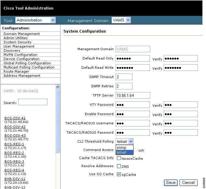
Step 5 ![]() On the System Configuration page, from the drop-down list for CLI Threshold Polling method, select telnet, as shown in Figure 5-1.
On the System Configuration page, from the drop-down list for CLI Threshold Polling method, select telnet, as shown in Figure 5-1.
Figure 5-1 Configuring the CLI Threshold Polling Method
Step 6 ![]() Click Save to save the domain configuration.
Click Save to save the domain configuration.
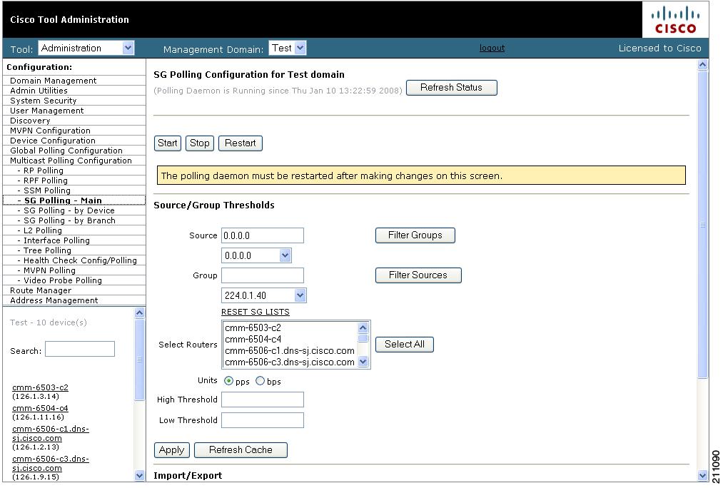
Step 7 ![]() To configure SG polling and set up PPS/BPS thresholds, select Multicast Polling Configuration > SG Polling - Main.
To configure SG polling and set up PPS/BPS thresholds, select Multicast Polling Configuration > SG Polling - Main.
The main SG Polling Configuration page opens, as shown in Figure 5-2.
Figure 5-2 SG Polling Configuration Page
Step 8 ![]() Configure PPS/BPS thresholds as described in the "SG Polling - Main" section of the User Guide for Cisco Multicast Manager 2.5 at the following location:
Configure PPS/BPS thresholds as described in the "SG Polling - Main" section of the User Guide for Cisco Multicast Manager 2.5 at the following location:
Configuring Tree Polling
Multicast trees can change due to network outages or in response to establishment of more optimal flow paths. Because tree changes might impact video quality immediately or in the future, it is important for network operators to be notified of changes in multicast trees.
To configure tree polling, you must first create a trace file by drawing a multicast tree and saving it. You can then use the saved tree as a baseline for configuring tree polling.
The trace file name that you specify must have this format:
<channel_name>_<ad_zone>_<Mcast-Group>_<source-IP>
where channel_name is the name of the channel, ad_zone is the name of the Ad zone, Mcast-Group is the address of the multicast group, and source-IP is the IP address of the source. For example:
PBS_National_232-0-1-32_12-101-2-18
To configure tree polling:
Step 1 ![]() Start the Diagnostics tool.
Start the Diagnostics tool.
Step 2 ![]() Click Show All Groups.
Click Show All Groups.
The Multicast Diagnostics page appears, as shown in Figure 5-3.
Figure 5-3 Multicast Diagnostics Page
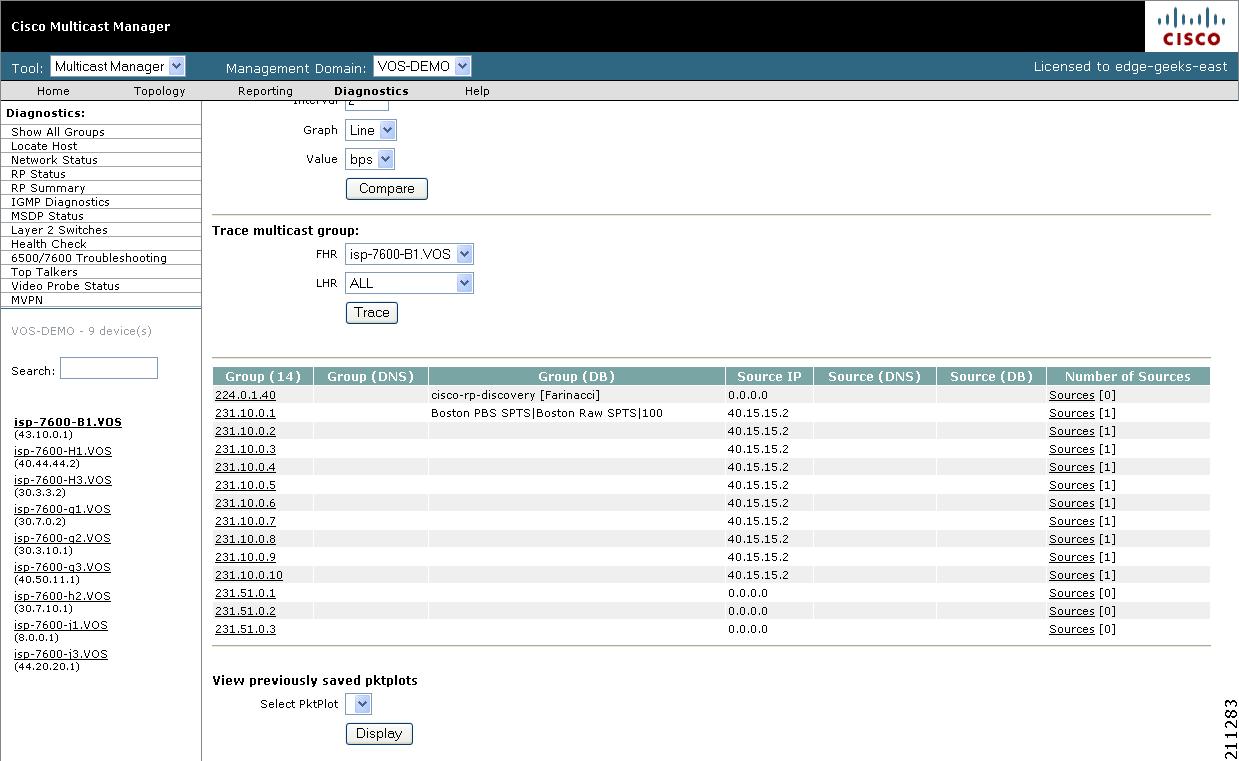
Step 3 ![]() From the drop-down list below the Source field in the Set Source and Group to Work On pane, select a source to work on.
From the drop-down list below the Source field in the Set Source and Group to Work On pane, select a source to work on.
Step 4 ![]() From the drop-down list below the Group field in the Set Source and Group to Work On pane, select a group to work on.
From the drop-down list below the Group field in the Set Source and Group to Work On pane, select a group to work on.
The Multicast Diagnostics page appears with the source and group selected.
Step 5 ![]() For additional details, see the "Show All Groups" section in the User Guide for Cisco Multicast Manager 2.5 at this location:
For additional details, see the "Show All Groups" section in the User Guide for Cisco Multicast Manager 2.5 at this location:
http://www.cisco.com/en/US/docs/net_mgmt/cisco_multicast_manager/2.5/user/guide/cmm_dt.html
CMM draws a tree diagram of the tree.
Step 6 ![]() To save the trace to use as a baseline for tree polling, in the Trace File field, enter a name the trace file, and then click Save As.
To save the trace to use as a baseline for tree polling, in the Trace File field, enter a name the trace file, and then click Save As.
Note ![]() The trace file name that you specify must have this format:
The trace file name that you specify must have this format:
<channel_name>_<ad_zone>_<Mcast-Group>_<source-IP>
where channel_name is the name of the channel, ad_zone is the name of the Ad zone, Mcast-Group is the address of the multicast group, and source-IP is the IP address of the source. For example:
PBS_National_232-0-1-32_12-101-2-18
Step 7 ![]() To set up tree polling for the saved baseline, complete these steps:
To set up tree polling for the saved baseline, complete these steps:
a. ![]() Select the Administration tool.
Select the Administration tool.
b. ![]() Select Multicast Polling Configuration > Tree Polling.
Select Multicast Polling Configuration > Tree Polling.
The Tree Polling Configuration page opens, as shown in Figure 5-4.
Figure 5-4 Tree Polling Configuration Page
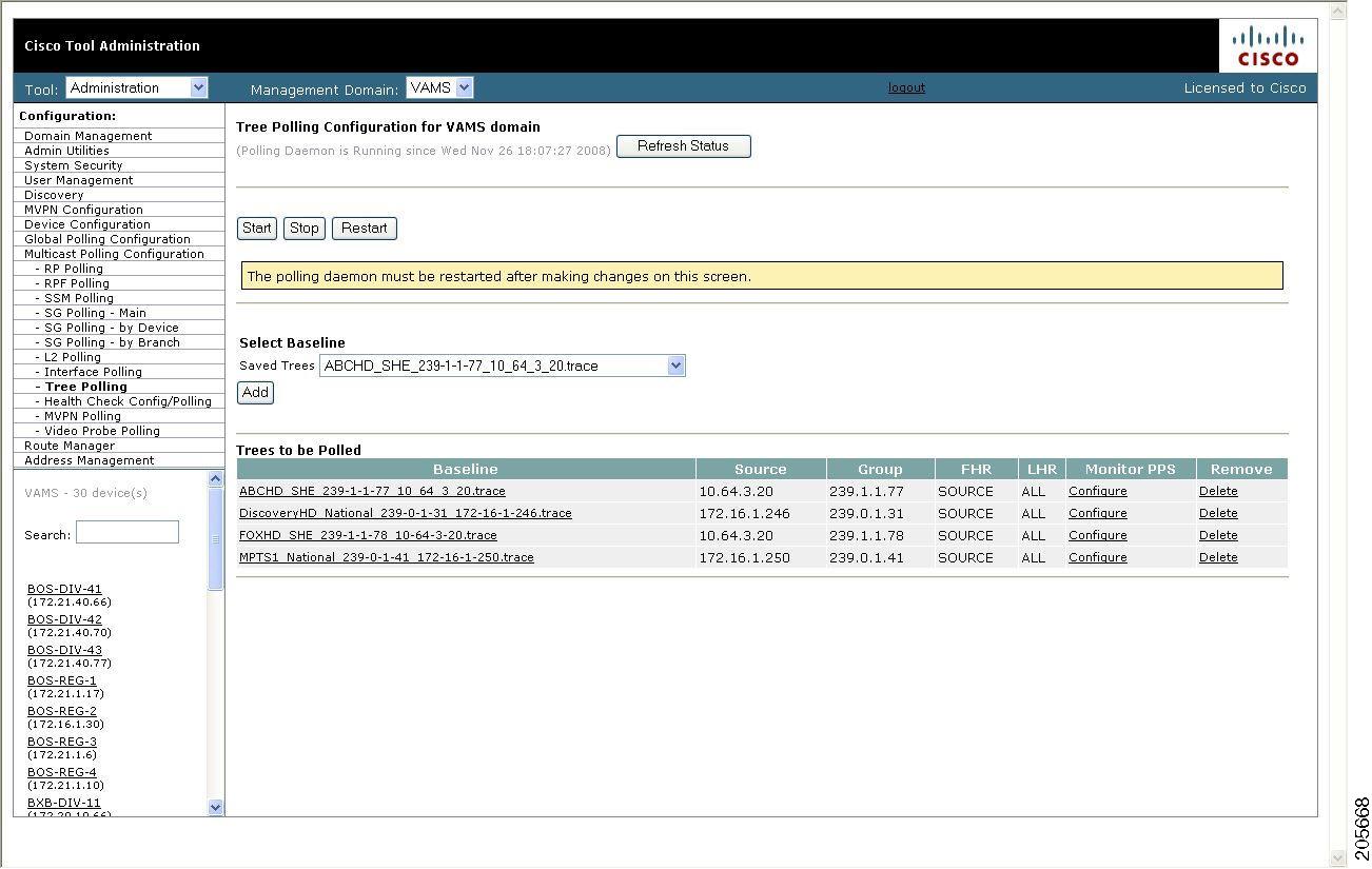
The Tree Polling Configuration page contains the following fields and buttons:
c. ![]() To monitor a tree, from the drop-down menu in the Saved Trees field, select the tree name, and click Add.
To monitor a tree, from the drop-down menu in the Saved Trees field, select the tree name, and click Add.
d. ![]() To specify how often the tree is polled:
To specify how often the tree is polled:
–![]() Click Global Polling Configuration.
Click Global Polling Configuration.
The Global Polling Configuration Page appears.
–![]() Click Tree Polling Interval, and on the dialog that appears, specify the time interval for tree polling.
Click Tree Polling Interval, and on the dialog that appears, specify the time interval for tree polling.
–![]() Save your changes.
Save your changes.
–![]() Click Set to save your global polling configuration.
Click Set to save your global polling configuration.
The tree is drawn in the background for every interval that you set up for tree polling. This tree is compared with the tree saved in the database. If it is different, a trap is sent, and a report is generated.
Configuring Health Checks
The CMM application provides the ability to set up health checks that check and report on the status of critical components of your IP multicast network. Health checks can check the status of RPs, MSDP peering, the presence of sources and groups, and the status of multicast trees.
You should create a health check for every important source and group in your multicast network.
To configure health check polling:
Step 1 ![]() Select the Administration tool.
Select the Administration tool.
Step 2 ![]() Select Multicast Polling Configuration > Health Check Config/Polling.
Select Multicast Polling Configuration > Health Check Config/Polling.
The Health Check Config/Polling page opens, as shown in Figure 5-5.
Figure 5-5 Health Check Polling Configuration Page
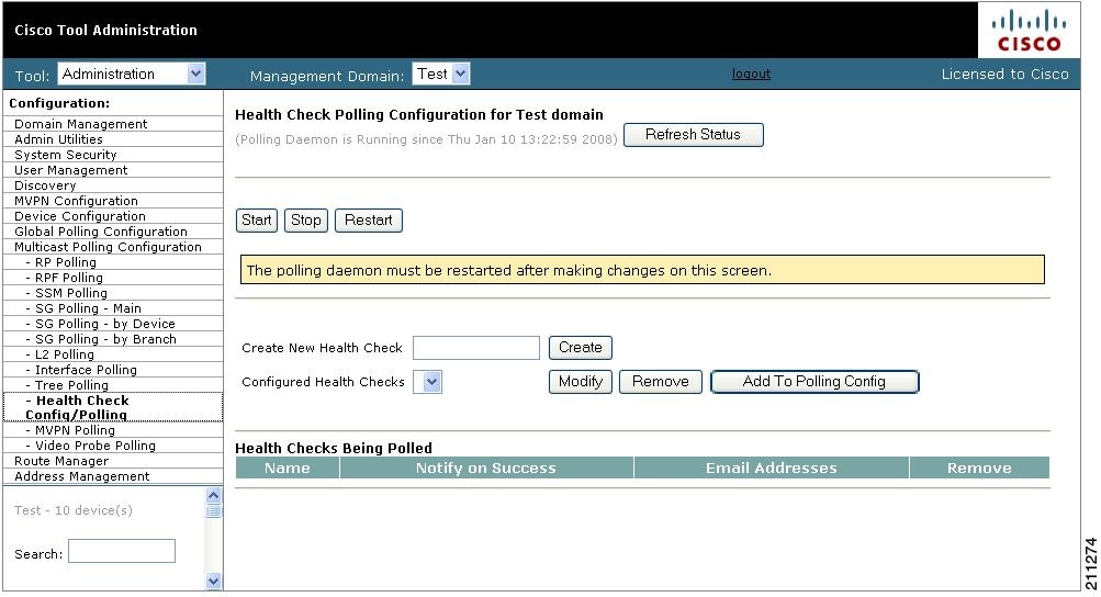
The Health Check Config/Polling page contains the following fields and buttons:
Configuring IP Multicast Heartbeat Monitoring
The CMM application can monitor the heartbeat of the routers that are forwarding a video flow. This is useful to confirm that the traffic stream is active.
To set up heartbeat monitoring requires that a downstream router or host has joined a multicast group or a static IGMP has been set; a data path must be established through the router that is configured for heartbeat monitoring.
Configuring heartbeat monitoring consists of two steps:
1. ![]() Configuring IP multicast on a router.
Configuring IP multicast on a router.
2. ![]() Enabling monitoring for the router.
Enabling monitoring for the router.
Configuring IP Multicast Heartbeat on the Router
To configure IP multicast heartbeat on a router for which you want to enable IP multicast heartbeat, enter the following commands:
snmp-server enable traps ipmulticast
ip multicast heartbeat <ip_address> <minimum_number> <intervals> <interval_length>
where ip_address is the IP address of the router, minimum_number is the minimum number of intervals, intervals is the number of intervals, and interval_length is the length of the intervals in seconds.
The following is an example configuration of the ip multicast heartbeat command:
snmp-server enable traps ipmulticast-heartbeat
ip multicast heartbeat 224.0.1.53 1 1 10
Enabling Monitoring for the Router
To enable CMM monitoring for the router heartbeat, complete these steps to set the multicast group to monitor and specify the minimum number of packets that the router must process in an interval:
Step 1 ![]() Select Multicast Polling Configuration > SG Polling - Main.
Select Multicast Polling Configuration > SG Polling - Main.
The main SG Polling Configuration page opens.
Step 2 ![]() In the Group field, enter the IP address for the group to monitor.
In the Group field, enter the IP address for the group to monitor.
Step 3 ![]() In the Select Routers list, select the router that you want to monitor.
In the Select Routers list, select the router that you want to monitor.
Step 4 ![]() Scroll down to the bottom of the SG Polling configuration page and click Time-based thresholds (in the Time Threshold column).
Scroll down to the bottom of the SG Polling configuration page and click Time-based thresholds (in the Time Threshold column).
Step 5 ![]() Set the number of intervals to monitor and the length of the intervals in seconds.
Set the number of intervals to monitor and the length of the intervals in seconds.
Step 6 ![]() Click the Set Thresholds button to save your changes.
Click the Set Thresholds button to save your changes.
Step 7 ![]() On the SG Polling Configuration page, click Apply.
On the SG Polling Configuration page, click Apply.
Configure Video Probes
Each video probe in Cisco VAMS 1.5 monitors various parameters of the video flow through the network. For example, you might configure a video probe to monitor the amount of jitter or delay in a video stream.
For each video probe deployed in the network, you must configure the thresholds for the conditions that you want to monitor. You must also configure the video probes to forward traps to CIC. (Refer to the probe documentation for information on adding the CIC IP addresses and related SNMP information to the video probe settings.)
Once you configure the video probe, if a monitored condition exceeds a configured threshold, the probe sends a corresponding trap to CIC, which shows the event in the TBSM GUI and the Webtop GUI.
Note ![]() CMM 2.5.4 will poll the IneoQuest probes even though the probes may also be sending traps to the Cisco ANA.
CMM 2.5.4 will poll the IneoQuest probes even though the probes may also be sending traps to the Cisco ANA.
Bridge Technologies Video Probe
To configure the Bridge Technologies video probe for operation in the video transport network, refer to the documentation that comes with the product. These documents assist the network planner when integrating the Bridge Technologies video probes with the Cisco VAMS 1.5:
VB120 Broadcast IP-Probe User's Manual v. 4.0
IneoQuest Video Probe
To configure the IneoQuest video probe for operation in the video transport network, refer to the documentation that comes with the product. These documents assist the network planner when integrating the IneoQuest video probes with the Cisco VAMS 1.5:
•![]() Hardware User's Guide
Hardware User's Guide
•![]() IQMediaAnalyzer Application User's Guide
IQMediaAnalyzer Application User's Guide
Mixed Signals Video Probe
To configure the Mixed Signals video probe for operation in the video transport network, refer to the documentation that comes with the product. These documents assist the network planner when integrating the Mixed Signals video probes with the Cisco VAMS 1.5:
The Mixed Signals Sentry Digital Content Monitor User Guide
PixelMetrix Video Probe
To configure the PixelMetrix video probe for operation in the video transport network, refer to the documentation that comes with the product. These documents assist the network planner when integrating the PixelMetrix video probes with the Cisco VAMS 1.5:
DVStation-IP-3 User Manual, Software Version 4.17
Tektronix Video Probe
To configure the Tektronix video probe for operation in the video transport network, refer to the documentation that comes with the product. These documents assist the network planner when integrating the Tektronix video probes with the Cisco VAMS 1.5.
•![]() MTM400 MPEG Transport Stream Monitor User Manual
MTM400 MPEG Transport Stream Monitor User Manual
•![]() MTM400 MPEG Transport Stream Monitor Technical Reference
MTM400 MPEG Transport Stream Monitor Technical Reference
•![]() MTM400 MPEG Transport Stream Monitor Programmer Manual
MTM400 MPEG Transport Stream Monitor Programmer Manual
Run the Setup for IPTV Script
The Setup for IPTV activation script sets up network configuration parameters for the Cisco devices in the Cisco VAMS 1.5.
The script runs:
•![]() ANA startup.
ANA startup.
•![]() Every two hours.
Every two hours.
•![]() Whenever the managed device reloads.
Whenever the managed device reloads.
•![]() When you activate it in ANA NetworkVision (see procedure).
When you activate it in ANA NetworkVision (see procedure).
The hourly run checks the IPTV configuration of the managed VNEs. If a VNE does not have the expected IPTV configuration, the script applies the IPTV configuration parameters to the device.
Note ![]() Configure the supported devices and load them with IPTV-enabled IOS images. The IPTV script does not recognize the devices without IPTV-enabled IOS images. (See the "Before You Install" section on page 3-1.)
Configure the supported devices and load them with IPTV-enabled IOS images. The IPTV script does not recognize the devices without IPTV-enabled IOS images. (See the "Before You Install" section on page 3-1.)
To manually run the IPTV activation script for setup:
Step 1 ![]() Log in to ANA NetworkVision.
Log in to ANA NetworkVision.
Step 2 ![]() Right-click a VNE in the network map.
Right-click a VNE in the network map.
Step 3 ![]() In the right-click menu, choose Management > Setup for IPTV.
In the right-click menu, choose Management > Setup for IPTV.
Step 4 ![]() In the Setup for IPTV window, click the Execute button.
In the Setup for IPTV window, click the Execute button.
The result of the script appears in the same window under the Result tab.
Note ![]() If the selected VNE already has its IPTV configuration, the result indicates ALREADY CREATED, and the script does not run.
If the selected VNE already has its IPTV configuration, the result indicates ALREADY CREATED, and the script does not run.
Run the Cleanup from IPTV Script
You run the Cleanup from IPTV activation script when you want to remove the IPTV extensions from a VNE that is in the Cisco VAMS 1.5. When you remove the extensions, the VNE will not be able to process the IPTV requests.
To run the Cleanup from IPTV script:
Step 1 ![]() Log in to ANA NetworkVision.
Log in to ANA NetworkVision.
Step 2 ![]() Right-click the VNE in the network map.
Right-click the VNE in the network map.
Step 3 ![]() In the right-click menu, choose Management > Cleanup from IPTV.
In the right-click menu, choose Management > Cleanup from IPTV.
The Cleanup from IPTV script runs and removes the IPTV extensions from the selected VNE.
CIC Configuration
The CIC configuration includes:
•![]() Installation of Cisco ANA to Netcool Adapter
Installation of Cisco ANA to Netcool Adapter
•![]() Installing the IBM Tivoli Netcool Rules Files
Installing the IBM Tivoli Netcool Rules Files
•![]() Installing IBM Tivoli Netcool View For ANA
Installing IBM Tivoli Netcool View For ANA
•![]() Configuring of Channel Mapping databases
Configuring of Channel Mapping databases
•![]() Configuration of the VAMS Cross-Launch menu
Configuration of the VAMS Cross-Launch menu
Prerequisites
Verify that the following patches are in Cisco ANA 3.6 Service Pack 1:
•![]() CSCsj08845—Gateway sends duplicate alarms to the Netcool server.
CSCsj08845—Gateway sends duplicate alarms to the Netcool server.
•![]() CSCsj16298—ANA2CIC—alarm notification sent to the drool misses properties.
CSCsj16298—ANA2CIC—alarm notification sent to the drool misses properties.
Note ![]() Back up existing post.drl file, under the main/data directory. If the directory contains a new drools rules1 file, merge them with the post.drl file that will be added to the directory once the next step is complete.
Back up existing post.drl file, under the main/data directory. If the directory contains a new drools rules1 file, merge them with the post.drl file that will be added to the directory once the next step is complete.
Installation of Cisco ANA to Netcool Adapter
To install the Cisco ANA to the Netcool Adapter:
Step 1 ![]() Go to the release site and FTP the ps-Netcool-adapter-1.1-src.zip file:
Go to the release site and FTP the ps-Netcool-adapter-1.1-src.zip file:
http://wwwin-nmbu.cisco.com/Patches/patch-publisher/listbyproduct.cfm?searchbug=CSCsk84768 to the /export/home/sheer4 directory
Step 2 ![]() Unzip the file under the /export/home/sheer4 directory.
Unzip the file under the /export/home/sheer4 directory.
Note ![]() This procedure will override any existing post.drl files.
This procedure will override any existing post.drl files.
Step 3 ![]() Back up.
Back up.
Step 4 ![]() If you are installing an AVM80 on the ANA gateway, skip this step.
If you are installing an AVM80 on the ANA gateway, skip this step.
To install the avm80.xml file on an ANA unit:
Copy the avm80.xml from directory ~Main/ registry/ConfigurationFiles/127.0.0.1 to an appropriate directory:
cp SHEERHOME/Main/registry/ConfigurationFiles/127.0.0.1/avm80.xml $SHEERHOME/Main/
registry/ConfigurationFiles/<unit_IP>
Step 5 ![]() In the drool installation, the JAR file contains the post.drl file. After unzipping and extracting the file, the file will override the existing data/post.drl file.
In the drool installation, the JAR file contains the post.drl file. After unzipping and extracting the file, the file will override the existing data/post.drl file.
All relevant rules should have a condition tag set to true as follows:
java:condition>true</java:condition>
Set the following rules to true:
•![]() sendAlarmNotification: Handles alarm and ticket notifications.
sendAlarmNotification: Handles alarm and ticket notifications.
•![]() sendAlarmNotificationOnProvisioningEvents: Handles provisioning events.
sendAlarmNotificationOnProvisioningEvents: Handles provisioning events.
Step 6 ![]() Change the IP address 0.0.0.0 to the unit IP address if installed on the Cisco ANA unit. Then, run the following ANA gateway commands:
Change the IP address 0.0.0.0 to the unit IP address if installed on the Cisco ANA unit. Then, run the following ANA gateway commands:
./runRegTool.sh -gs 127.0.0.1 add 0.0.0.0 avm99/services/bsm/avm80
./runRegTool.sh -gs 127.0.0.1 set 0.0.0.0 avm99/services/bsm/avm80/maxmem 512
./runRegTool.sh -gs 127.0.0.1 set 0.0.0.0 avm99/services/bsm/avm80/id 80
./runRegTool.sh -gs 127.0.0.1 set 0.0.0.0 avm99/services/bsm/avm80/enable false
./runRegTool.sh -gs 127.0.0.1 set 0.0.0.0 avm99/services/bsm/avm80/reqavm 0
./runRegTool.sh -gs 127.0.0.1 set 0.0.0.0 avm99/services/bsm/avm80/classesjar
"classes.jar:ANA-Netcool-Adapter-1.1.jar"
Step 7 ![]() Verify that AVM80 has been updated correctly. If it has not, repeat the process.
Verify that AVM80 has been updated correctly. If it has not, repeat the process.
Step 8 ![]() Edit the avm80.xml file containing the correct destination IP address and port number.
Edit the avm80.xml file containing the correct destination IP address and port number.
On the ANA gateway:
./runRegTool.sh -gs 127.0.0.1 set 127.0.0.1
avm80/services/trap-forwarder/destination-list/<Destination IP> 162
On the ANA unit:
./runRegTool.sh -gs 127.0.0.1 set <Unit_IP>
avm80/services/trap-forwarder/destination-list/<Destination IP> 162
Step 9 ![]() To change the AVM80 trap type for the ANA gateway, run one of the following commands:
To change the AVM80 trap type for the ANA gateway, run one of the following commands:
./runRegTool.sh -gs 127.0.0.1 set 127.0.0.1 avm80/services/trap-forwarder/snmp-version v1
./runRegTool.sh -gs 127.0.0.1 set 127.0.0.1 avm80/services/trap-forwarder/snmp-version v2
To change the AVM80 trap type for the ANA unit, run one of the following commands:
./runRegTool.sh -gs 127.0.0.1 set <Unit_IP> avm80/services/trap-forwarder/snmp-version v1
./runRegTool.sh -gs 127.0.0.1 set <Unit_IP> avm80/services/trap-forwarder/snmp-version v2
Step 10 ![]() From the ~/Main directory, run the mvm command.
From the ~/Main directory, run the mvm command.
~/Main]% ./mvm.csh
Step 11 ![]() Open the ANA Manage application and start the AVM80.
Open the ANA Manage application and start the AVM80.
Log Level Configuration
To configure the log level for log monitoring:
Step 1 ![]() Run the following ANA gateway commands from the ~/Main directory:
Run the following ANA gateway commands from the ~/Main directory:
Note ![]() Replace the IP address 127.0.0.1 with the ANA unit server IP address if the AVM80 does not reside in the Cisco ANA gateway.
Replace the IP address 127.0.0.1 with the ANA unit server IP address if the AVM80 does not reside in the Cisco ANA gateway.
./runRegTool.sh -gs 127.0.0.1 set 127.0.0.1
avm80/services/logger/log4j.category.com.cisco.integrations.cic DEBUG
./runRegTool.sh -gs 127.0.0.1 set 127.0.0.1
avm80/services/logger/log4j.category.Netcool-adapter DEBUG
Step 2 ![]() Use Cisco ANA Manage to stop and start the AVM80.
Use Cisco ANA Manage to stop and start the AVM80.
Step 3 ![]() To change the log level for log monitoring:
To change the log level for log monitoring:
a. ![]() Go to the machine where the AVM80 is running.
Go to the machine where the AVM80 is running.
b. ![]() Log in as user sheer.
Log in as user sheer.
c. ![]() Telnet to 0 2080.
Telnet to 0 2080.
d. ![]() Change the directory to logger.
Change the directory to logger.
e. ![]() Change the log level to DEBUG/ERROR/FATAL.
Change the log level to DEBUG/ERROR/FATAL.
After changing the previous value to the desired level, the logs will appear in the 80.out directory.
Installing the IBM Tivoli Netcool Rules Files
Configure the IBM Tivoli Netcool with a specific rules file created to identify the information that the Cisco ANA sends.
To install the IBM Tivoli Netcool rules files:
Step 1 ![]() First FTP the NCKL-1.2.3-CFM.tar.gz file to Netcool server.
First FTP the NCKL-1.2.3-CFM.tar.gz file to Netcool server.
Step 2 ![]() Put it in the directory $OMNIHOME/probes/linux2x86.
Put it in the directory $OMNIHOME/probes/linux2x86.
Step 3 ![]() Unzip the file:
Unzip the file:
gunzip NCKL-1.2.3-CFM.tar.gz
Step 4 ![]() Untar the file:
Untar the file:
tar -vxf NCKL-1.2.3-CFM.tar
This should create a new directory called rules in the $OMNIHOME/probes/linux2x86 directory.
Step 5 ![]() Edit the .cshrc file as root and add the following environment variable at the end of the file after all the environment variables:
Edit the .cshrc file as root and add the following environment variable at the end of the file after all the environment variables:
$NC_RULES_HOME=$OMNIHOME/probes/linux2x86/rules
Note ![]() Be sure to use the correct path.
Be sure to use the correct path.
Step 6 ![]() Exit the session and open a new session as root.
Exit the session and open a new session as root.
Step 7 ![]() FTP the Cisco EPM rules files to the $NC_RULES_HOME/include-snmptrap directory.
FTP the Cisco EPM rules files to the $NC_RULES_HOME/include-snmptrap directory.
The rule files names are:
•![]() cisco-CISCO-EPM-NOTIFICATION-MIB.adv.include.snmptrap.rules
cisco-CISCO-EPM-NOTIFICATION-MIB.adv.include.snmptrap.rules
•![]() cisco-CISCO-EPM-NOTIFICATION-MIB.include.snmptrap.lookup
cisco-CISCO-EPM-NOTIFICATION-MIB.include.snmptrap.lookup
•![]() cisco-CISCO-EPM-NOTIFICATION-MIB.include.snmptrap.rules
cisco-CISCO-EPM-NOTIFICATION-MIB.include.snmptrap.rules
•![]() cisco-CISCO-EPM-NOTIFICATION-MIB.sev.snmptrap.lookup
cisco-CISCO-EPM-NOTIFICATION-MIB.sev.snmptrap.lookup
Step 8 ![]() FTP the ANA-New Probe.txt file from the caveat CSCsk84768 to the $NC_RULES_HOME/include-snmptrap directory and rename it by replacing the original cisco-EPM file:
FTP the ANA-New Probe.txt file from the caveat CSCsk84768 to the $NC_RULES_HOME/include-snmptrap directory and rename it by replacing the original cisco-EPM file:
mv ANA-New Probe.txt cisco-CISCO-EPM-NOTIFICATION-MIB.include.snmptrap.rules
Step 9 ![]() Edit the snmptrap.rules file located in directory $OMNIHOME/probes/linux2x86/rules to contain the following new lines:
Edit the snmptrap.rules file located in directory $OMNIHOME/probes/linux2x86/rules to contain the following new lines:
Lookup files
a. ![]() include:
include:
"$NC_RULES_HOME/include-snmptrap/cisco-CISCO-EPM-NOTIFICATION-MIB.include.snmptrap.lookup"
Severity files
table cisco-CISCO-EPM-NOTIFICATION-MIB_sev =
"$NC_RULES_HOME/include-snmptrap/cisco-CISCO-EPM-NOTIFICATION-MIB.sev.snmptrap.lookup"
default = {"Unknown","Unknown","Unknown"}
Rules files
a. ![]() include
include
"$NC_RULES_HOME/include-snmptrap/cisco-CISCO-EPM-NOTIFICATION-MIB.include.snmptrap.rules"
Step 10 ![]() Edit your snmptrap.rules file, located in directory $NC_RULES_HOME.
Edit your snmptrap.rules file, located in directory $NC_RULES_HOME.
At the end you will see the following section:
##########
# The following include statement is required by Netcool's advanced correlation
# logic.
##########
if(nmatch(@Agent, "Cisco-IOS"))
{
include "$NC_RULES_HOME/include-syslog/CorrScore.include.syslog.rules"
include "$NC_RULES_HOME/include-syslog/PreClass.include.syslog.rules"
}
else
{
include "$NC_RULES_HOME/include-snmptrap/CorrScore.include.snmptrap.rules"
include "$NC_RULES_HOME/include-snmptrap/PreClass.include.snmptrap.rules"
}
##########
# End of advanced correlation include files.
##########
##########
# Enter "compatibility" includes below with the following syntax:
#
# include "<$NCHOME>/etc/rules/include-compat/<rulesfile>.include.compat.rules"
##########
include "$NC_RULES_HOME/include-compat/omnibus36.include.compat.rules"
include "$NC_RULES_HOME/include-compat/AdvCorr36.include.compat.rules"
#include "$NC_RULES_HOME/include-compat/neusecure-gw-snmptrap.include.compat.rules"
#include "$NC_RULES_HOME/include-compat/neusecure-gw.include.compat.rules"
##########
# End of "compatibility" includes.
##########
Comment the entire section out, and then try again.
Step 11 ![]() From the directory $OMNIHOME/probes/linux2x86, run the following command:
From the directory $OMNIHOME/probes/linux2x86, run the following command:
nco_p_mttrapd -rulesfile ./rules/snmptrap.rules &
Step 12 ![]() If you get the following error:
If you get the following error:
"ld.so.1: nco_p_mttrapd: fatal: libOpl_r.so.1: open failed: No such file or directory"
Run the probe from a different location such as:
/opt/Netcool/omnibus/probes]#./nco_p_mttrapd -rulesfile ./linux2x86/rules/snmptrap.rules &
Installing IBM Tivoli Netcool View For ANA
To install IBM Tivoli Netcool View for ANA:
Step 1 ![]() FTP the Cisco ANA AdapterView.elc file from caveat CSCsk84768 to the Netcool server.
FTP the Cisco ANA AdapterView.elc file from caveat CSCsk84768 to the Netcool server.
Step 2 ![]() Put it in the $OMNIHOME/utils directory.
Put it in the $OMNIHOME/utils directory.
Step 3 ![]() Open Netcool View, choose File > Open.
Open Netcool View, choose File > Open.
Step 4 ![]() Browse and select the $OMNIHOME/utils/Cisco ANA.elc file.
Browse and select the $OMNIHOME/utils/Cisco ANA.elc file.
 Feedback