- Preface
-
- Introducing the Cisco SNS 3415 and Cisco SNS 3495 Hardware Appliances
- Preparing to Install the Cisco SNS 3415 and Cisco SNS 3495 Hardware Appliances
- Installing the Cisco SNS 3415 and Cisco SNS 3495 Hardware Appliances
- Installing and Configuring Cisco Secure Access Control System with Cisco SNS 3415 and Cisco SNS 3495 Appliances
Installation and Upgrade Guide for Cisco Secure Access Control System 5.8
Bias-Free Language
The documentation set for this product strives to use bias-free language. For the purposes of this documentation set, bias-free is defined as language that does not imply discrimination based on age, disability, gender, racial identity, ethnic identity, sexual orientation, socioeconomic status, and intersectionality. Exceptions may be present in the documentation due to language that is hardcoded in the user interfaces of the product software, language used based on RFP documentation, or language that is used by a referenced third-party product. Learn more about how Cisco is using Inclusive Language.
- Updated:
- September 25, 2015
Chapter: Preparing to Install the Cisco SNS 3415 and Cisco SNS 3495 Hardware Appliances
Preparing to Install the Cisco SNS 3415 and Cisco SNS 3495 Hardware Appliances
This section provides information on how you can prepare your site for safely installing the Cisco SNS-3415 or Cisco SNS-3495 appliance.
This section contains the following topics:
■![]() Unpacking and Inspecting the Server
Unpacking and Inspecting the Server
■![]() Preparing for Server Installation
Preparing for Server Installation
Safety Guidelines
Note: Before you install, operate, or service a Cisco SNS-3415 or Cisco SNS-3495 appliance, review the Regulatory Compliance and Safety Information for Cisco Secure Access Control System for important safety information.
Warning: IMPORTANT SAFETY INSTRUCTIONS
This warning symbol means danger. You are in a situation that could cause bodily injury. Before you work on any equipment, be aware of the hazards involved with electrical circuitry and be familiar with standard practices for preventing accidents. Use the statement number provided at the end of each warning to locate its translation in the translated safety warnings that accompanied this device.
Statement 1071![]()
Warning: To prevent the system from overheating, do not operate it in an area that exceeds the maximum recommended ambient temperature of: 40° C (104° F).
Statement 1047![]()
Warning: The plug-socket combination must be accessible at all times, because it serves as the main disconnecting device.
Statement 1019![]()
Warning: This product relies on the building’s installation for short-circuit (overcurrent) protection. Ensure that the protective device is rated not greater than: 250 V, 15 A.
Statement 1005![]()
Warning: Installation of the equipment must comply with local and national electrical codes.
Statement 1074![]()
When you are installing a server, use the following guidelines:
■![]() Plan your site configuration and prepare the site before installing the server. See the Cisco UCS Site Preparation Guide for the recommended site planning tasks.
Plan your site configuration and prepare the site before installing the server. See the Cisco UCS Site Preparation Guide for the recommended site planning tasks.
■![]() Ensure that there is adequate space around the server to allow for servicing the server and for adequate airflow. The airflow in this server is from front to back.
Ensure that there is adequate space around the server to allow for servicing the server and for adequate airflow. The airflow in this server is from front to back.
■![]() Ensure that the air-conditioning meets the thermal requirements listed in the Server Specifications.
Ensure that the air-conditioning meets the thermal requirements listed in the Server Specifications.
■![]() Ensure that the cabinet or rack meets the requirements listed in the Rack Requirements.
Ensure that the cabinet or rack meets the requirements listed in the Rack Requirements.
■![]() Ensure that the site power meets the power requirements listed in the Server Specifications. If available, you can use an uninterruptible power supply (UPS) to protect against power failures.
Ensure that the site power meets the power requirements listed in the Server Specifications. If available, you can use an uninterruptible power supply (UPS) to protect against power failures.
Caution: Avoid UPS types that use ferroresonant technology. These UPS types can become unstable with systems such as the Cisco UCS, which can have substantial current draw fluctuations from fluctuating data traffic patterns.![]()
Unpacking and Inspecting the Server
Caution: When handling internal server components, wear an ESD strap and handle modules by the carrier edges only. ![]()
Note: Keep the shipping container in case the server requires shipping in the future.
Note: The chassis is thoroughly inspected before shipment. If any damage occurred during transportation or any items are missing, contact your customer service representative immediately.
To inspect the shipment, follow these steps:
1.![]() Remove the server from its cardboard container and save all packaging material.
Remove the server from its cardboard container and save all packaging material.
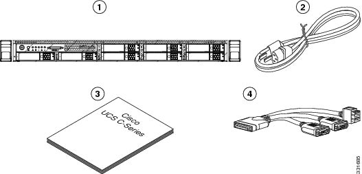
2.![]() Compare the shipment to the equipment list provided by your customer service representative and Figure 1. Verify that you have all items.
Compare the shipment to the equipment list provided by your customer service representative and Figure 1. Verify that you have all items.
3.![]() Check for damage and report any discrepancies or damage to your customer service representative. Have the following information ready:
Check for damage and report any discrepancies or damage to your customer service representative. Have the following information ready:
■![]() Invoice number of shipper (see the packing slip)
Invoice number of shipper (see the packing slip)
■![]() Model and serial number of the damaged unit
Model and serial number of the damaged unit
■![]() Effect of damage on the installation
Effect of damage on the installation
Figure 1 Shipping Box Contents
|
|
|
||
|
|
|
Preparing for Server Installation
This section provides information about preparing for server installation, and it includes the following topic
Installation Guidelines
Warning: To prevent the system from overheating, do not operate it in an area that exceeds the maximum recommended ambient temperature of: 40° C (104° F).
Statement 1047 ![]()
Warning: The plug-socket combination must be accessible at all times, because it serves as the main disconnecting device.
Statement 1019 ![]()
Warning: This product relies on the building's installation for short-circuit (overcurrent) protection. Ensure that the protective device is rated not greater than: 250 V, 15 A.
Statement 1005 ![]()
Warning: Installation of the equipment must comply with local and national electrical codes.
Statement 1074 ![]()
When you are installing a server, use the following guidelines:
■![]() Plan your site configuration and prepare the site before installing the server. See the Cisco UCS Site Preparation Guide for the recommended site planning tasks.
Plan your site configuration and prepare the site before installing the server. See the Cisco UCS Site Preparation Guide for the recommended site planning tasks.
■![]() Ensure that there is adequate space around the server to allow for servicing the server and for adequate airflow. The airflow in this server is from front to back.
Ensure that there is adequate space around the server to allow for servicing the server and for adequate airflow. The airflow in this server is from front to back.
■![]() Ensure that the air-conditioning meets the thermal requirements listed in the Server Specifications.
Ensure that the air-conditioning meets the thermal requirements listed in the Server Specifications.
■![]() Ensure that the cabinet or rack meets the requirements listed in the Rack Requirements section.
Ensure that the cabinet or rack meets the requirements listed in the Rack Requirements section.
■![]() Ensure that the site power meets the power requirements listed in the Server Specifications. If available, you can use an uninterruptible power supply (UPS) to protect against power failures.
Ensure that the site power meets the power requirements listed in the Server Specifications. If available, you can use an uninterruptible power supply (UPS) to protect against power failures.
Caution: Avoid UPS types that use ferroresonant technology. These UPS types can become unstable with systems such as the Cisco SNS-3415 or Cisco SNS-3495 appliance, which can have substantial current draw fluctuations from fluctuating data traffic patterns. ![]()
Rack Requirements
This section provides the requirements for the standard open racks.
The rack must be of the following type:
■![]() A standard 19-in. (48.3-cm) wide, four-post EIA rack, with mounting posts that conform to English universal hole spacing, per section 1 of ANSI/EIA-310-D-1992.
A standard 19-in. (48.3-cm) wide, four-post EIA rack, with mounting posts that conform to English universal hole spacing, per section 1 of ANSI/EIA-310-D-1992.
■![]() The rack post holes can be square.38-inch (9.6 mm), round.28-inch (7.1 mm), #12-24 UNC, or #10-32 UNC when you use the supplied slide rails.
The rack post holes can be square.38-inch (9.6 mm), round.28-inch (7.1 mm), #12-24 UNC, or #10-32 UNC when you use the supplied slide rails.
■![]() The minimum vertical rack space per server must be one RU, equal to 1.75 in. (44.45 mm).
The minimum vertical rack space per server must be one RU, equal to 1.75 in. (44.45 mm).
Equipment Requirements
The slide rails supplied by Cisco Systems for this server do not require tools for installation. The inner rails (mounting brackets) are pre-attached to the sides of the server.
Slide Rail Adjustment Range
The slide rails for this server have an adjustment range of 24 to 36 inches (610 to 914 mm).
Server Specifications
This section lists the technical specifications for the server and includes the following sections:
■![]() Physical SpecificationsPhysical Specifications
Physical SpecificationsPhysical Specifications
Physical Specifications
Table 1 lists the physical specifications of the server.
|
|
|
|---|---|
Environmental Specifications
Table 2 lists the environmental specifications of the server.
|
|
|
|---|---|
| Derate the maximum temperature by 1°C per every 305 meters of altitude above sea level. |
|
Power Specifications
The power specifications for the two power supply options are listed in the following sections:
You can get more specific power information for your exact server configuration by using the Cisco UCS Power Calculator:
http://www.cisco.com/assets/cdc_content_elements/flash/dataCenter/cisco_ucs_power_calculator/
Note: Do not mix power supply types in the server. Both power supplies must be either 450W or 650W.
Note: ACS 5.8 supports an optional redundant power supply unit for Cisco SNS-3415-K9.
450-W Power Supply
Table 3 lists the environmental specifications of the server.
|
|
|
|---|---|
650-W Power Supply
Table 4 lists the environmental specifications of the server.
|
|
|
|---|---|
 Feedback