- Preface
- Broadband Access Center Overview
- Broadband Access Center Architecture
- Configuration Workflows
- CPE Provisioning Overview
- Configuration Templates Management
- DOCSIS Configuration
- PacketCable Voice Configuration
- CableHome Configuration
- Managing Broadband Access Center
- Monitoring Broadband Access Center
- Understanding the Administrator User Interface
- Using the Administrator User Interface
- Configuring Broadband Access Center
- Support Tools and Advanced Concepts
- Database Management
- Troubleshooting Broadband Access Center
- Alert and Error Messages
- Option Support
- Mapping PacketCable DHCP Options to BAC Properties
- Provisioning API Use Cases
- FAQs on Provisioning Broadband Access Center
- Glossary
- Index 4.1
Cisco Broadband Access Center Administrator Guide 4.1
Bias-Free Language
The documentation set for this product strives to use bias-free language. For the purposes of this documentation set, bias-free is defined as language that does not imply discrimination based on age, disability, gender, racial identity, ethnic identity, sexual orientation, socioeconomic status, and intersectionality. Exceptions may be present in the documentation due to language that is hardcoded in the user interfaces of the product software, language used based on RFP documentation, or language that is used by a referenced third-party product. Learn more about how Cisco is using Inclusive Language.
- Updated:
- April 30, 2010
Chapter: Troubleshooting Broadband Access Center
- Troubleshooting Checklist
- Troubleshooting Devices by Device ID
- Troubleshooting Using the Diagnostics Tool
Troubleshooting Cisco Broadband Access Center
This chapter provides details on how to troubleshoot with Cisco Broadband Access Center (Cisco BAC). This chapter describes:
•![]() Troubleshooting Devices by Device ID
Troubleshooting Devices by Device ID
•![]() Troubleshooting Using the Diagnostics Tool
Troubleshooting Using the Diagnostics Tool
•![]() Bundling Server State for Support
Bundling Server State for Support
•![]() Troubleshooting DOCSIS Networks
Troubleshooting DOCSIS Networks
•![]() Troubleshooting PacketCable eMTA Provisioning
Troubleshooting PacketCable eMTA Provisioning
For a list of FAQs related to Cisco BAC provisioning, see "FAQs on Provisioning Broadband Access Center."
Troubleshooting Checklist
While troubleshooting with Cisco BAC, use the checklist described in Table 16-1.

Troubleshooting Devices by Device ID
You can use this feature to collect detailed diagnostics about one or more specific devices. Troubleshooting information includes all server interactions related to a given device or a group of devices. This information includes administrator user interface operations, RDU application programming interface (API) operations, DPE interactions with devices, and interserver DPE-to-RDU interactions.
You can enable or disable diagnostics via group management for one or more specific devices without turning logging on, and without searching through log files for specific device information.
Cisco BAC maintains a list of devices, based on device identifiers (MAC addresses and DUIDs), for which detailed diagnostics are collected. Troubleshooting information is stored centrally at the RDU and is maintained on a per-device basis. Neither DPEs nor Cisco Network Registrar extensions store this data. Rather, they forward this information to the RDU, which, upon receiving information, writes it to the troubleshooting.log file in the BPR_DATA/rdu/logs directory.
The troubleshooting.log file is different from other log files such as rdu.log, dpe.log, and audit.log. It only logs detailed troubleshooting information relating to a specific set of devices in the diagnostics mode.
If the connection from the DPE or Network Registrar extension to the RDU is lost, any new troubleshooting events occurring on the DPE or Network Registrar extension are discarded. The logging of troubleshooting information resumes only after the connection to the RDU is restored.
The DPE maps MAC addresses and DUIDs of a specific device being diagnosed to the IP address for that device. The DPE receives IP updates from the Network Registrar extensions for the devices being diagnosed.
Any modifications to the device tracking list, such as the addition of a new device or a group, take place immediately at all servers; you do not have to reboot the RDU or the DPE. The log files on the respective servers list the current list of devices in the diagnostics mode.

Configuring Devices for Troubleshooting
Device diagnostics is disabled until one or more devices are set in diagnostics mode.
To enable diagnostics for a device, the device must be preregistered in the Cisco BAC RDU. If the device is not yet preregistered, add the device from the Manage Devices page by clicking the Add button. For information on adding devices, see Adding Device Records.
You can configure a maximum number of devices in diagnostics mode to prevent inadvertently putting too many devices in this mode and thus diminishing server performance. By default, this number is set at 25. To configure the maximum number of devices allowed in troubleshooting mode from the administrator user interface, click the Systems Defaults page via the Configuration > Defaults tabs. Enter a value in the Maximum Diagnostics Device Count field.
Relating a Device to a Group
You can troubleshoot a device by relating it to a specific group. Use the Relate function to associate a device, using its MAC address or its DUID, to a specific group, which is in turn associated with a specific group type. (See Relating and Unrelating Devices.) Doing so records an extraordinarily large volume of information for a device; you can then use the information to troubleshoot potential problems.
Table 16-2 identifies a possible workflow using the Relate and Unrelate functions.
Viewing List of Devices in Diagnostics Mode
When you enable troubleshooting for a device, the device is automatically added to a special device group that contains a list of devices in troubleshooting mode. The group type is system and the group name is system-diagnostics. You can access the list of devices in this group from the API or the administrator user interface.
To view a list of devices currently enabled for diagnostics:
Step 1 ![]() From the Manage Devices page, click the Search Type drop-down list and select Group Search.
From the Manage Devices page, click the Search Type drop-down list and select Group Search.
Step 2 ![]() From the Group Name (Group Type) drop-down list, select the system-diagnostics (system) option to view all the devices in diagnostics mode.
From the Group Name (Group Type) drop-down list, select the system-diagnostics (system) option to view all the devices in diagnostics mode.
Step 3 ![]() Click Search.
Click Search.

Note ![]() An alternative way to view the list of devices in diagnostics mode is to consult the RDU log (rdu.log) and the DPE log (dpe.log) files. The list of devices is logged whenever the server is started and whenever there is a change in the list of devices enabled for diagnostics.
An alternative way to view the list of devices in diagnostics mode is to consult the RDU log (rdu.log) and the DPE log (dpe.log) files. The list of devices is logged whenever the server is started and whenever there is a change in the list of devices enabled for diagnostics.
The devices enabled for diagnostics appear in the log files with the log level of 5-notification. For details on log files, see Logging Events.
Examples
This example features log output while troubleshooting an MTA:
bac-test.example.com:	2005 03 04 18:38:24 EST:	%BAC-DIAGNOSTICS-3-4055:	[##MTA-9a Unconfirmed
FQDN Request Received from [/10.10.10.5 ['kdcquery']. Client with IP Address [10.10.20.2]
and MAC Address [1,6,00:00 :ca:b7:7e:91]]]
bac-test.example.com:	2005 03 04 18:38:24 EST:	%BAC-DIAGNOSTICS-3-4082:	[Results of BACC
Lookup. FQDN: [1-6-00-00-ca-b7-7e-91.example.com MAC: 1,6,00:00:ca:b7:7e:91. Client with
IP Address [10.10.20.2] and MAC Address [1,6,00:00:ca:b7:7e:91]]]
bac-test.example.com:	2005 03 04 18:38:24 EST:	%BAC-DIAGNOSTICS-3-4070:	[##MTA-9b FQDN Reply
Sent to [/10.10.20.2(41142) for MTA 1,6,00:00:ca:b7:7e:91. Client with IP Address
[10.10.20.2] and MAC Address [1,6, 00:00:ca:b7:7e:91]]]
bac-test.example.com:	2005 03 04 18:38:26 EST:	%BAC-DIAGNOSTICS-3-4132:	[##MTA-13 Incoming
APREQ received from [/10.10.20.2:1293. Client with IP Address [10.10.20.2] and MAC
Address [1,6,00:00:ca:b7:7e:91]]]
bac-test.example.com:	2005 03 04 18:38:26 EST:	%BAC-DIAGNOSTICS-3-4141:	[##MTA-13 APREP sent
to [/10.10.20.2(1293) For MTA 1,6,00:00:ca:b7:7e:91. Client with IP Address [10.10.20.2]
and MAC Address [1,6,00:00: ca:b7:7e:91]]]
bac-test.example.com:	2005 03 04 18:38:26 EST:	%BAC-DIAGNOSTICS-3-0764:	[[##MTA-15 SNMPv3
INFORM Received From 10.10.20.2. Client with IP Address [10.10.20.2] and MAC Address
[1,6,00:00:ca:b7:7e:91]]]
bac-test.example.com:	2005 03 04 18:38:26 EST:	%BAC-DIAGNOSTICS-3-0764:	[[##MTA-19 SNMPv3 SET
Sent to 10.10.20.2. Client with IP Address [10.10.20.2] and MAC Address
[1,6,00:00:ca:b7:7e:91]]]
bac-test.example.com:	2005 03 04 18:38:26 EST:	%BAC-DIAGNOSTICS-3-1092:	[Received a TFTP
[read] request from [10.10.20.2:1271] for [bpr01060000cab77e910002]; Client with MAC
Address [1,6,00:00:ca:b7:7e:91] and IP Address [10.10.20.2]]
bac-test.example.com:	2005 03 04 18:38:26 EST:	%BAC-DIAGNOSTICS-3-1155:	[##MTA-23 Finished
handling [read] request from [10.10.20.2:1271] for [bpr01060000cab77e910002]; Transferred
[236] bytes to Client with MAC Address [1,6,00:00:ca:b7:7e:91] and IP Address
[10.10.20.2]]
bac-test.example.com:	2005 03 04 18:38:27 EST:	%BAC-DIAGNOSTICS-3-0764:	[[##MTA-25 SNMP
Provisioning State INFORM Received from 10.10.20.2. Client with IP Address [10.10.20.2]
and MAC Address [1,6,00:00:ca:b7:7e:91]]]
bac-test.example.com:	2005 03 04 18:38:27 EST:	%BAC-DIAGNOSTICS-3-0764:	[[MTA Configuration
Confirmed, Returned 'pass' as the final MTA provisioning state for 10.10.20.2. Client with
IP Address [10.10.20.2] and MAC Address [1,6,00:00:ca:b7:7e:91]]]
Troubleshooting Using the Diagnostics Tool
You can use the diagnostics tool to collect performance statistics—down to a specific type of statistic—for Cisco BAC servers. Using individual scripts for each task that this tool performs, you can:
•![]() Gather diagnostics concurrently (startDiagnostics.sh)
Gather diagnostics concurrently (startDiagnostics.sh)
•![]() Stop diagnostics prematurely (stopDiagnostics.sh)
Stop diagnostics prematurely (stopDiagnostics.sh)
•![]() Determine the status of diagnostics collection (statusDiagnostics.sh)
Determine the status of diagnostics collection (statusDiagnostics.sh)
You can run the diagnostic tool concurrently when you face an issue and need additional data for troubleshooting, or you can set it to run periodically on a given schedule via a cron job.
The diagnostic tool resides in the following locations for the:
•![]() RDU—BPR_HOME/rdu/diagnostics/bin
RDU—BPR_HOME/rdu/diagnostics/bin
•![]() DPE—BPR_HOME/dpe/diagnostics/bin
DPE—BPR_HOME/dpe/diagnostics/bin
•![]() Cisco Network Registrar—BPR_HOME/cnr_ep/diagnostics/bin
Cisco Network Registrar—BPR_HOME/cnr_ep/diagnostics/bin
Note ![]() You can bundle the collected diagnostics using the bundleState.sh script. For details, see Bundling Server State for Support.
You can bundle the collected diagnostics using the bundleState.sh script. For details, see Bundling Server State for Support.
Using the startDiagnostics.sh Tool
You can run the startDiagnostics.sh tool in two modes:
•![]() Interactive—In this mode, you can select the diagnostic data that you require from a list of options.
Interactive—In this mode, you can select the diagnostic data that you require from a list of options.
•![]() Noninteractive—In this mode, you first generate a response file that contains arguments. Then, when you run the startDiagnostics.sh script, the tool collects diagnostics data based on the arguments specified in the response file.
Noninteractive—In this mode, you first generate a response file that contains arguments. Then, when you run the startDiagnostics.sh script, the tool collects diagnostics data based on the arguments specified in the response file.
Syntax Description
startDiagnostics.sh [-r response_file] | [-g response_file] [-help]
•![]() startDiagnostics.sh—Runs diagnostics in the interactive mode
startDiagnostics.sh—Runs diagnostics in the interactive mode
•![]() response_file—Identifies the response file
response_file—Identifies the response file
•![]() -r response_file—Uses the response file generated to run the diagnostics tool in the noninteractive mode
-r response_file—Uses the response file generated to run the diagnostics tool in the noninteractive mode
•![]() -g response_file—Generates the response file without running diagnostics
-g response_file—Generates the response file without running diagnostics
•![]() -help—Displays help for the tool. You must use the -help option exclusively. Do not use this with any other option.
-help—Displays help for the tool. You must use the -help option exclusively. Do not use this with any other option.
Running startDiagnostics.sh in Interactive Mode
When you enter startDiagnostics.sh without specifying any argument, the diagnostics tool runs in the interactive mode and prompts you to select the statistics that you want from the RDU, the DPE, and the Network Registrar servers.
Syntax Description
startDiagnostics.sh [-help]
•![]() startDiagnostics.sh—Runs diagnostics in the interactive mode
startDiagnostics.sh—Runs diagnostics in the interactive mode
•![]() -help—Displays help for the tool. You must use the -help option exclusively. Do not use this with any other option.
-help—Displays help for the tool. You must use the -help option exclusively. Do not use this with any other option.
Examples
# ./startDiagnostics.sh
Please enter directory where to put output files [] /var/CSCObac
Please enter the duration of the diagnostic (sec) [600]
Please select statistics you would like to gather on RDU
CPU statistics (y/n/q)? [y]
Process statistics (y/n/q)? [n]
IO statistics (y/n/q)? [y]
Memory statistics (y/n/q)? [y]
Network statistics (y/n/q)? [y]
RDU API traffic (y/n/q)? [y]
RDU CNR traffic (y/n/q)? [y]
RDU DPE traffic (y/n/q)? [y]
RDU CNR extension traffic (y/n/q)? [y]
RDU SNMP traffic (y/n/q)? [y]
System Configuration (y/n/q)? [y]
Enter addition argument for RDU API traffic
Please enter RDU Server port [49187]
Enter addition arguments for RDU DPE traffic
Enter DPE ip addr if you want to capture traffic by ip addr [] 10.10.29.1
Enter DPE port number if you want to capture traffic by port number [] 49186
Enter addition arguments for RDU CNR_EX traffic
Enter Ip addr if you want to capture traffic by Cnr Extension IP addr [] 10.10.85.2
Enter port number if you want to capture traffic by Cnr Extension port []
You could run statusDiagnostics.sh to find out the status of the diagnostics.
You could run stopDiagnostics.sh to stop the diagnostics.
You could run bundleState.sh to bundle the output when diagnostics is complete.
Note ![]() If you do not enable statistics for the following options, the tool does not request values for additional arguments, as featured in the example:
If you do not enable statistics for the following options, the tool does not request values for additional arguments, as featured in the example:
•![]() RDU-API traffic
RDU-API traffic
•![]() RDU-DPE traffic
RDU-DPE traffic
•![]() RDU-Network Registrar extension traffic
RDU-Network Registrar extension traffic
After you run the startDiagnostics.sh tool, output files for each statistic are created under the directory in which you run the tool. You can also bundle the output files and forward them to the Cisco Technical Assistance Center for support. To do so, enter y at the System Diagnostics Capture prompt.
For example:
System Configuration (y/n/q)? [y]
For more details on bundling server state, see Bundling Server State for Support.
Running startDiagnostics.sh in Noninteractive Mode
Before running the startDiagnostics.sh tool in the noninteractive mode for the first time, you must generate the response file. Thereafter, you only need to run a single command, which collects diagnostics based on the arguments contained in the response file.
Syntax Description
startDiagnostics.sh {-g response_file | -r response_file} [-help]
•![]() -g—Generates the response file. You need to use this option only when generating a response file for the first time.
-g—Generates the response file. You need to use this option only when generating a response file for the first time.
•![]() -r—Runs the diagnostics tool using the response file
-r—Runs the diagnostics tool using the response file
•![]() response_file—Specifies the name of the response file
response_file—Specifies the name of the response file
•![]() -help—Displays help for the tool. You must use the -help option exclusively. Do not use this with any other option.
-help—Displays help for the tool. You must use the -help option exclusively. Do not use this with any other option.
Examples
This results occurs when you generate the response file.
# ./startDiagnostics.sh -g response.txt
Please enter directory where to put output files [] /var/CSCObac
Please enter the duration of the diagnostic (sec) [600]
Please select statistics you would like to gather on RDU
CPU statistics (y/n/q)? [y]
Process statistics (y/n/q)? [n]
IO statistics (y/n/q)? [y]
Memory statistics (y/n/q)? [y]
Network statistics (y/n/q)? [y]
RDU API traffic (y/n/q)? [y] n
RDU CNR traffic (y/n/q)? [y]
RDU DPE traffic (y/n/q)? [y] n
RDU CNR extension traffic (y/n/q)? [y] n
RDU SNMP traffic (y/n/q)? [y]
System Configuration (y/n/q)? [y]
Finished generate response file (response.txt).
The response.txt is generated under the directory in which you run the startDiagnostics.sh script; in this case, BPR_HOME/rdu/diagnostics/bin. A sample response file generated for RDU diagnostics is featured here:
test.bundle.direcotry=/var/CSCObac
test.bundle.duration.sec=100
test.cpu.enable=true
test.process.enable=false
test.io.enable=true
test.memory.enable=true
test.network.enable=true
test.rdu_api_traffic.enable=true
test.rdu_cnr_traffic.enable=true
test.rdu_dpe_traffic.enable=true
test.rdu_cnr_ex_traffic.enable=true
test.rdu_snmp_traffic.enable=true
test.system_config.enable=true
test.rdu.port=49187
test.dpe.port=49186
test.dpe.ip=10.10.29.1
test.cnr_ex.ip=10.10.85.2
test.cnr_ex.port=
EOF
This result occurs when you run the diagnostics tool using the response file that you have generated.
# ./startDiagnostics.sh -r response.txt
You could run statusDiagnostics.sh to find out the status of the diagnostics.
You could run stopDiagnostics.sh to stop the diagnostics.
After you run the startDiagnostics.sh tool, output files for each statistic are created under the directory in which you run the tool.
Using the statusDiagnostics.sh Tool
Use the statusDiagnostics.sh tool to determine the status of diagnostic collection for the statistics that you require.
Syntax Description
statusDiagnostics.sh, which displays the status of diagnostic collection for each statistic.
Note ![]() You cannot use the -help option with the statusDiagnostics.sh tool.
You cannot use the -help option with the statusDiagnostics.sh tool.
Examples
# ./statusDiagnostics.sh
CPU diagnostic is running.
Process diagnostics stopped.
IO diagnostic is running.
Memory diagnostic is running.
Network diagnostic is running.
Rdu api traffic diagnostic is running.
Rdu cnr traffic diagnostic is running.
Rdu dpe traffic diagnostic is running.
Rdu cnr_ex traffic diagnostic is running.
Rdu snmp traffic diagnostic is running.
Using the stopDiagnostics.sh Tool
Use the stopDiagnostics.sh tool to stop running diagnostics for any one statistic or for all statistics. You can run this tool in the interactive mode or noninteractive mode.
Running stopDiagnostics.sh in Interactive Mode
Running stopDiagnostics.sh in the interactive mode, without any argument, prompts you to specify if you want to stop diagnostics for all statistics or for specific statistics.
Syntax Description
stopDiagnostics.sh [-help]
•![]() stopDiagnostics.sh—Stops diagnostic collection in the interactive mode.
stopDiagnostics.sh—Stops diagnostic collection in the interactive mode.
•![]() -help—Displays help for the tool. You must use the -help option exclusively. Do not use this with any other option.
-help—Displays help for the tool. You must use the -help option exclusively. Do not use this with any other option.
Examples
# ./stopDiagnostics.sh
This script allowed to stop specific diagnostic or all diagnostics.
If you would like to stop specific diagnostics, say no to question below.
Would you like to stop all diagnostics (y/n/q)? [y]
Running stopDiagnostics.sh in Noninteractive Mode
Running stopDiagnostics.sh in the noninteractive mode stops diagnostics for all statistics.
Syntax Description
stopDiagnostics.sh -a [-help]
•![]() -a—Stops diagnostics for all statistics without prompting you.
-a—Stops diagnostics for all statistics without prompting you.
•![]() -help—Displays help for the tool. You must use the -help option exclusively. Do not use this with any other option.
-help—Displays help for the tool. You must use the -help option exclusively. Do not use this with any other option.
Examples
# ./stopDiagnostics.sh -a
#
Bundling Server State for Support
You can generate server configuration and other diagnostics information using the diagnostics tools in the BPR_HOME/{rdu | dpe}/diagnostics/bin directory. (For information on how to run these tools, see Troubleshooting Using the Diagnostics Tool.) To make this diagnostic information available for support to the Cisco Technical Assistance Center, you must bundle the output directory that is created using the diagnostics tools into an archive. To perform this task, you use the bundleState.sh tool.
Note that the bundleState.sh tool does not gather diagnostics; it only zips and tars the data that tools such as startDiagnostics.sh collect.
At a minimum, the diagnostics that you bundle must include information related to system configuration. To generate system information, use either:
•![]() captureConfiguration.sh—Collects system configuration information such as mount and disk setup, memory, and operating system and hardware data. When running this script, you must specify the output directory.
captureConfiguration.sh—Collects system configuration information such as mount and disk setup, memory, and operating system and hardware data. When running this script, you must specify the output directory.
•![]() startDiagnostics.sh—Collects performance statistics for Cisco BAC servers. When running this script to capture system configuration, you must enter y at the System Configuration prompt. For example:
startDiagnostics.sh—Collects performance statistics for Cisco BAC servers. When running this script to capture system configuration, you must enter y at the System Configuration prompt. For example:
System Configuration (y/n/q)? [y]
For details, see Using the startDiagnostics.sh Tool.
For specific problems, Cisco support personnel may instruct you to collect additional diagnostics and add it to the bundle.
Syntax Description
bundleState.sh archive_directory output_directory [-help]
•![]() archive_directory—Directory where you want to bundle.
archive_directory—Directory where you want to bundle.
•![]() output_directory—Directory where you want to output the bundle.
output_directory—Directory where you want to output the bundle.
•![]() -help—Displays help for the tool. You must use the -help option exclusively. Do not use this with any other option.
-help—Displays help for the tool. You must use the -help option exclusively. Do not use this with any other option.
Examples
# ./bundleState.sh /var/CSCObac /var/CSCObac
/var/CSCObac/state-20071129-064042
Creating state bundle for Cisco support...
+ /var/CSCObac/state-20071129-064042.bpr
+ Compressing state bundle...
+ Size: 3736K compressed, 83776K uncompressed
Troubleshooting DOCSIS Networks
For information on troubleshooting the DOCSIS technology with respect to Cisco BAC and the Cisco uBR7246 CMTS, see Troubleshooting uBR Cable Modems Not Coming Online at:
http://www.cisco.com/en/US/tech/tk86/tk89/technologies_tech_note09186a0080094eb1.shtml
Troubleshooting PacketCable eMTA Provisioning
This section features information that will help you solve possible issues in a PacketCable voice technology deployment.
This section assumes that you are familiar with the PacketCable Multimedia Terminal Adapter (MTA) Device Provisioning Specification, PKT-SPPROV1.5-I01-050128. See the PacketCable website for details.
Provisioning PacketCable embedded MTAs (eMTAs) is a relatively complex process; however, with the right tools and "tricks of the trade," getting eMTAs operational can be straightforward.
This section assumes that Network Registrar and Cisco BAC are both in use; however, much of the information also applies for other deployments. Basic knowledge of Network Registrar (scopes, policies, basic DNS zone setup, and record entry) and Cisco BAC (Class of Service, DHCP Criteria, files, and Cisco BAC directory structure) is assumed.
The PacketCable eMTA provisioning process consists of 25 steps for the Secure flow; the Basic flow has far fewer steps. To troubleshoot eMTAs, knowledge of these 25 steps from the PacketCable provisioning specification is absolutely essential. See Chapter 7 "PacketCable Voice Configuration."
This section contains the following topics:
Components
Before troubleshooting eMTAs, you should be familiar with the following system components.
•![]() eMTA
eMTA
•![]() KDC
KDC
•![]() PacketCable Provisioning Server
PacketCable Provisioning Server
eMTA
The eMTA is a cable modem and an MTA in one box, with a common software image. The CM and MTA each have their own MAC addresses and each performs DHCP to get its own IP address. The eMTA contains, at minimum, three certificates. One certificate is a unique MTA certificate. A second certificate identifies the MTA manufacturer. Both the device and manufacture certificates are sent by the MTA to authenticate itself to the KDC. The third certificate is a telephony root certificate used to verify the certificates sent by the KDC to the MTA. The KDC certificates will be chained from the telephony root, therefore the telephony root must reside on the MTA to validate the authenticity of the KDC certificates. The MTA portion receives its own configuration file, which it uses to identify its controlling call agent, among other things.
DHCP Server
The DOCSIS specifications mandate that cable modems negotiate their IP addresses using DHCP. The MTA, like most CPE on a DOCSIS network, must use DHCP to obtain its IP address and other crucial information (DNS servers, PacketCable Option 122 for Kerberos realm name, provisioning server FQDN).
Note ![]() The cable modem portion, in addition to its normally required DHCP options, also requests, and must receive, Option 122 suboption 1, which it passes to the MTA portion as the IP address of the correct DHCP server from which to accept offers.
The cable modem portion, in addition to its normally required DHCP options, also requests, and must receive, Option 122 suboption 1, which it passes to the MTA portion as the IP address of the correct DHCP server from which to accept offers.
When using Cisco BAC with PacketCable support, be aware that a correctly configured Cisco BAC will automatically populate the ToD server, DNS servers, TFTP server, as well as the Option 122 fields; these do not need to be explicitly set in the Network Registrar policy.
DNS Server
The Domain Name System (DNS) server is fundamental in PacketCable provisioning. The PacketCable provisioning server, which is the device provisioning engine (DPE) in a Cisco BAC architecture, must have an address (A) record in the appropriate zone, because its fully qualified domain name (FQDN) is provided to the MTA in Option 122 by the DHCP server. The KDC realm must have a zone of the same name as the realm name containing a server (SRV) record that contains the FQDN of the Kerberos server.
The Kerberos server identified in the SRV record must itself have an A record in the appropriate zone. The call management server (CMS) identified in the MTA configuration file must also have an A record in the appropriate zone. Lastly, the MTAs themselves must have A records in the appropriate zone, because the CMS reaches the MTA by resolving its FQDN. Dynamic DNS (DDNS) is the preferred method of creating A records for the MTA. See Cisco Network Registrar documentation for information on configuring and troubleshooting DDNS.
KDC
The KDC is responsible for authenticating MTAs. As such, it must check the MTA certificate, and provide its own certificates so that the MTA can authenticate the KDC. It also communicates with the DPE (the provisioning server) to validate that the MTA is provisioned on the network.
PacketCable Provisioning Server
The PacketCable provisioning server is responsible for communicating the location of the MTA configuration file to the MTA, and/or provisioning MTA parameters via SNMP. SNMPv3 is used for all communication between the MTA and the provisioning server. The keys used to initiate SNMPv3 communication are obtained by the MTA during its authentication phase with the KDC. Provisioning server functionality is provided by the DPE in a Cisco BAC architecture.
Call Management Server
The call management server (CMS) is essentially a soft switch, or call-agent, with additional PacketCable functionality to control, among other things, quality of service on a cable network. The MTA sends a network call signaling (NCS) restart in progress (RSIP) message to the CMS upon successful PacketCable provisioning.
Key Variables
This section describes the key variables required to provision an eMTA correctly.
Certificates
The MTA_Root.cer file contains the MTA root certificate (a certificate that is rooted in the official PacketCable MTA root).
You must know in advance what telephony root certificate is required for the MTAs you want to provision. Deployments in production networks use telephony certificates rooted in the PacketCable real root. There is also a PacketCable test root used in testing environments.
The KDC certificates used by the KDC to authenticate itself to the MTA must be rooted in the same telephony root that is stored on the MTA (PacketCable real or test root). Most MTA vendors support test images that have Telnet and/or HTTP login capabilities so that you can determine which telephony root is enabled, and change the root used (in most cases, you can only select between the PacketCable real or test root).
The most common scenario has the KDC loaded with certificates (from the BPR_HOME/kdc/solaris/packetcable/certificates directory) as follows:
•![]() CableLabs_Service_Provider_Root.cer
CableLabs_Service_Provider_Root.cer
•![]() Service_Provider.cer
Service_Provider.cer
•![]() Local_System.cer
Local_System.cer
•![]() KDC.cer
KDC.cer
•![]() MTA_Root.cer
MTA_Root.cer
The first four certificates comprise the telephony certificate chain. The MTA_Root.cer file contains the MTA root used by the KDC to validate the certificates sent by the MTA.
Note ![]() See Using the PKCert.sh Tool, for information on installing and managing
See Using the PKCert.sh Tool, for information on installing and managing
KDC certificates.
To determine if you are using PacketCable test root, open the CableLabs_Service_Provider_Root.cer file in Windows, and validate that the Subject OrgName entry is O = CableLabs, and/or check that the Subject Alternative name reads CN=CABLELABS GENERATED TEST ROOT FOR EQUIPMENT TEST PURPOSES ONLY.
The KDC certificate (KDC.cer) contains the realm name to use. The realm name that Cisco BAC (and the corresponding DNS zone) is configured to use must match this realm name. Additionally, the MTA configuration file realm org name must match the organization name as seen in the telephony root.
The KDC certificate has a corresponding private key that must be installed in the BPR_HOME/kdc/solaris directory. Usually it is named KDC_private_key.pkcs8 or KDC_private_key_proprietary. When changing certificates, you must also change the private key.
Scope-Selection Tags
In most scenarios, Cisco BAC is involved in processing all DHCP requests from scopes with scope-selection tags that match selection criteria specified in the DHCP Criteria page of the Cisco BAC administrator user interface. Client class can also be used to tie scopes to Cisco BAC processing; ensure you make this association before you attempt to provision devices.
MTA Configuration File
The MTA configuration file contains the location of the CMS. Additionally, it must contain an entry for Realm Name. This value must match that of the certificate chain in use.
Certain table entries within the MTA configuration file are indexed by the realm name delivered to the MTA in Option 122. This realm name entry in the MTA configuration file must match that delivered in Option 122. For example, if DEF.COM was the realm name delivered in Option 122, MTA configuration file entries in the pktcMtaDevRealm table would be indexed with a suffix made up of the ASCII-coded character values (in dot-delimited decimal format when using the Cisco Broadband Configurator) of the realm name; for example 68.69.70.46.67.79.77. There are many free ASCII conversion pages available on the web to make this conversion easier.
Troubleshooting Tools
The 25 eMTA Secure provisioning steps contained in the PacketCable MTA Device Provisioning Specification are shown in Figure 7-1. This section describes:
•![]() Logs
Logs
•![]() Ethereal, SnifferPro, or Other Packet Capture Tools
Ethereal, SnifferPro, or Other Packet Capture Tools
Logs
These log files are used to maintain the following information:
•![]() The Network Registrar has two logs (name_dhcp_1_log and name_dns_1_log), which contain the most recent logging entries from Network Registrar. Look in these files for DHCP- or DNS-related problems.
The Network Registrar has two logs (name_dhcp_1_log and name_dns_1_log), which contain the most recent logging entries from Network Registrar. Look in these files for DHCP- or DNS-related problems.
•![]() The BPR_HOME/kdc/logs/kdc.log file shows all KDC interactions with MTAs, and KDC interactions with the DPE.
The BPR_HOME/kdc/logs/kdc.log file shows all KDC interactions with MTAs, and KDC interactions with the DPE.
•![]() The BPR_DATA/dpe/logs/dpe.log file shows the major steps related to SNMPv3 interaction with the MTA.
The BPR_DATA/dpe/logs/dpe.log file shows the major steps related to SNMPv3 interaction with the MTA.
Note ![]() Turning on the tracing of snmp, registration server, and registration server detail messages, using the command-line interface (CLI), helps to troubleshoot potential PacketCable problems. For information on the appropriate troubleshooting commands, see the Cisco Broadband Access Center DPE CLI Reference 4.1.
Turning on the tracing of snmp, registration server, and registration server detail messages, using the command-line interface (CLI), helps to troubleshoot potential PacketCable problems. For information on the appropriate troubleshooting commands, see the Cisco Broadband Access Center DPE CLI Reference 4.1.
Ethereal, SnifferPro, or Other Packet Capture Tools
A packet capture tool is indispensable when troubleshooting the eMTAs. The Ethereal version, as packaged by CableLabs, includes numerous packet decoders specific to PacketCable. These include the Kerberos AS and AP packets.
•![]() If you suspect that a specific failure is DHCP-related, capture packets while filtering on packets sourced from, or destined to, the CMTS cable interface IP address and the DHCP server IP address.
If you suspect that a specific failure is DHCP-related, capture packets while filtering on packets sourced from, or destined to, the CMTS cable interface IP address and the DHCP server IP address.
•![]() If you suspect that a specific failure is related to any of the 25 steps occurring after DHCP, filter all packets to and from the eMTA IP address. This provides a very concise, easy-to-follow trace of provisioning steps 5 through 25, as shown in Figure 7-1.
If you suspect that a specific failure is related to any of the 25 steps occurring after DHCP, filter all packets to and from the eMTA IP address. This provides a very concise, easy-to-follow trace of provisioning steps 5 through 25, as shown in Figure 7-1.
Troubleshooting Scenarios
The scenarios listed in Table 16-3 are possible failures involving eMTAs.
|
|
|
|
|---|---|---|
The KDC does not start. |
The KDC certificate does not correspond to the private key. |
Ensure that you have matching certificates and private key. |
The KDC license expired or is missing. |
Restore KDC license to BPR_HOME/kdc directory. |
|
The MTA device does not appear in the Cisco BAC Devices page. |
An incorrect cable helper address may have been configured. |
Fix the helper address. |
The scope-selection tags do not match the DHCP Criteria selected in the Cisco BAC user interface. |
Verify that the MTA scope-selection tags match those in the PacketCable DHCP Criteria created, in Cisco BAC, for the relevant MTAs. |
|
The Network Registrar extension point is not properly installed. |
Reinstall the Network Registrar extension point. See the Installation and Setup Guide for Cisco Broadband Access Center 4.1. |
|
The cable modem portion did not receive Option 122. |
Verify that the tags on the scope of the cable modem portion match the DOCSIS DHCP Criteria configured for Cisco BAC. |
|
The MTA device does not accept the DHCP offer and continually cycles through the DHCP flow. |
There are invalid DHCP options configured. |
Check that scope policy includes the DNS server option, and/or check that the cnr_ep.properties file includes entries for primary and secondary DNS servers. |
The DHCP offer may have come from a DHCP server different from the one indicated in the cable modem portion's Option 122 suboption 1. |
Check the cnr_ep.properties file to ensure that the main and backup DHCP servers are set correctly. |
|
Both the kdc.log file and the ethereal trace indicate that the MTA device never contacts the KDC. |
An incorrect DNS server is specified in the cnr_ep.properties file or the MTA scope policy, or both. |
Check or correct cnr_ep.properties DNS servers. |
A zone is missing or has been incorrectly set up for the Kerberos realm. |
Make sure a zone with same name as realm is created and contains an `SRV' record of format `_kerberos._udp 0 0 88 KDC FQDN'. |
|
There is a missing or incorrect KDC `A' record entry. |
Ensure that an `A' record exists for the FQDN contained in the Kerberos zone's `SRV' record. |
|
The DPE FQDN cannot be resolved. |
Ensure that the provFQDNs entry in dpe.properties has the correct FQDN and IP of the DPE. |
|
The KDC reports failure during the Kerberos AS-Request. |
The MTA certificate does not match the MTA root used by KDC. |
Verify that the MTA_Root.cer is correct by comparing the MTA_Root.cer against that used on a working system. If it is correct, the MTA itself could have a certificate problem. This situation is extremely rare and if this is the case, contact the MTA manufacturer. |
FQDN lookup by KDC to Prov Server failed. The device may not yet be provisioned in Cisco BAC. |
Verify that the device appears. It should be given both a Class of Service and a DHCP Criteria. |
|
A clock skew error. See PacketCable Workflows, for additional information. |
Ensure that all Cisco BAC network elements are clock-synced via NTP. See the Broadband Access Center DPE CLI Reference 4.1. |
|
A mismatch may exist between the KDC and the DPE. Note |
Check that these three entries exist in the BPR_HOME/kdc/solaris/keys directory: • • • The DPE FQDN and realm name on your system will be different from this example. Contents of these entries must match the entry in either the dpe.properties `KDCServiceKey' entry, or the keys generated using the KeyGen utility. |
|
The KDC reports success at the AS-Request/Reply (steps 9 and 10 in Figure 7-1), but the MTA device never moves past step 9. |
There is a certificate mismatch between the telephony root loaded or enabled on the MTA, and that loaded on the KDC. |
Check certificates on MTA and KDC. |
Although highly unlikely, it is possible that there is a corrupted telephony certificate chain. Note |
Ensure that the correct certificate is loaded or enabled on MTA. If no devices can be provisioned correctly, try a different certificate on the KDC. |
|
Failure at AP Request/Reply (step 14 in Figure 7-1). |
A clock skew error. See PacketCable Workflows, for additional information. |
Ensure that all Cisco BAC network elements are clock-synced via NTP. See the Broadband Access Center DPE CLI Reference. |
Cannot resolve Prov Server FQDN. |
Make sure that the provisioning server (DPE) has a correct DNS entry. |
|
There is no route from the MTA to the DPE. |
Correct the routing problem. |
|
The MTA device never issues a TFTP request for a configuration file. |
There is no route to the TFTP server running on the DPE. |
Correct the routing problem. |
The MTA device never receives the TFTP configuration file. |
The configuration file is not cached at the DPE. |
Wait until the next provisioning attempt, at which time the file should be cached. If this fails, reset the MTA. |
A conflicting TFTP server option is included in the network registrar MTA scope policy. |
Because Cisco BAC inserts the DPE address for the TFTP server, you can safely remove this option from the policy. |
|
The MTA device receives a configuration file, but the DPE fails to receive the SNMP Inform (step 25 in Figure 7-1) as seen in the dpe.log file. |
One of: • • • |
Ensure that the MTA configuration file is consistent. |
The MTA device reports success (step 25 in Figure 7-1) although an RSIP is not sent. |
The MTA cannot resolve the IP address of the CMS FQDN given in the MTA configuration file. |
Verify that a DNS entry exists for the CMS. |
The MTA cannot reach the IP address(es) of the CMS. This is an indication that no route is configured. |
Resolve all routing problems. |
|
The MTA device reports success (step 25 in Figure 7-1), although it proceeds to contact the KDC again for CMS service. |
The MTA configuration file points to an incorrect cable modem. |
Correct the configuration file, or reconfigure the Cisco BTS 10200 to use the FQDN listed in the configuration file. |
The MTA configuration file has its pktcMtaDevCmsIPsecCtrl value missing, or it is set to 1. This means it will perform secure NCS call signaling, or it will use an ASCII suffix that does not match that of the CMS FQDN. |
Correct the configuration file. If you intend to perform secure signaling, take the necessary steps to configure the KDC and the BTS for support. |
|
The MTA device reports success (step 25 in Figure 7-1), RSIPs, but gets no response or gets an error in response from the soft switch. |
The MTA is unprovisioned or has been incorrectly provisioned on the Cisco BTS 10200. |
Provision MTA on the Cisco BTS 10200. |
An eMTA DNS entry does not exist. |
Place an entry in the correct DNS zone for the eMTA. Dynamic DNS is the preferred method. See Cisco Network Registrar documentation for information on enabling DDNS. |
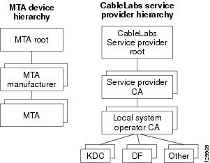
Certificate Trust Hierarchy
There are two certificate hierarchies affiliated with Cisco BAC PacketCable, the MTA Device Certificate Hierarchy and the CableLabs Service Provider Certificate Hierarchy, as shown in Figure 16-1.
Figure 16-1 PacketCable Certificate Hierarchy
Before implementing PacketCable in Cisco BAC, you should thoroughly familiarize yourself with these technology documents:
•![]() RFC 2459 Internet X.509 Public Key Infrastructure Certificate and CRL Profile
RFC 2459 Internet X.509 Public Key Infrastructure Certificate and CRL Profile
•![]() DOCSIS Baseline Privacy Plus Interface Specification, SP-BPI+-I11-040407, April 7, 2004
DOCSIS Baseline Privacy Plus Interface Specification, SP-BPI+-I11-040407, April 7, 2004
Note ![]() While Euro PacketCable uses the security specifications from PacketCable [PKT-SP-SEC-I08-030415], some changes are needed in relation to the digital certificates that are used in a Euro-PacketCable environment. To keep Euro PacketCable and PacketCable as alike as possible, Euro PacketCable uses all PacketCable security technology, including new revisions of the security specifications [PKTSP-SEC-I08-030415].
While Euro PacketCable uses the security specifications from PacketCable [PKT-SP-SEC-I08-030415], some changes are needed in relation to the digital certificates that are used in a Euro-PacketCable environment. To keep Euro PacketCable and PacketCable as alike as possible, Euro PacketCable uses all PacketCable security technology, including new revisions of the security specifications [PKTSP-SEC-I08-030415].
The elements of the Euro-PacketCable certificates that are different from the PacketCable certificates are indicated in the tables below.
For Euro PacketCable, the Euro-PacketCable certificates are the only valid certificates; any requirements that are stated in [PKT-SP-SEC-I08-030415] for PacketCable that refer to PacketCable Certificates are changed to the corresponding requirements for the Euro-PacketCable certificates.
Euro-PacketCable-compliant eMTAs must have the Euro-DOCSIS root CVC CA's public key stored in the cable modem's nonvolatile memory instead of in the DOCSIS CVC CA's public key. Standalone MTAs that comply with Euro PacketCable must have the tComLabs CVC Root Certificate and the tComLabs CVC CA certificate stored in non-volatile memory. The CVC of manufacturers are verified by checking the certificate chain.
Certificate Validation
PacketCable certificate validation in general involves validation of an entire chain of certificates. For example, when the provisioning server validates an MTA Device certificate, the following chain of certificates is validated:
MTA Root Certificate + MTA Manufacturer Certificate + MTA Device Certificate
The signature on the MTA Manufacturer Certificate is verified with the MTA Root Certificate and the signature on the MTA Device Certificate is verified with the MTA Manufacturer Certificate. The MTA Root Certificate is self-signed and is known in advance to the provisioning server. The public key present in the MTA Root Certificate is used to validate the signature on this same certificate.
Usually the first certificate in the chain is not explicitly included in the certificate chain that is sent over the wire. In the cases where the first certificate is explicitly included it must already be known to the verifying party ahead of time and must not contain any changes to the certificate with the possible exception of the certificate serial number, validity period, and the value of the signature. If changes other than these exist in the CableLabs Service Provider Root Certificate that was passed over the wire in comparison to the known CableLabs Service Provider Root Certificate, the device making the comparison must fail the certificate verification.
The exact rules for certificate chain validation must fully comply with RFC 2459, where they are referred to as Certificate Path Validation. In general, X.509 certificates support a liberal set of rules for determining if the issuer name of a certificate matches the subject name of another. The rules are such that two name fields may be declared to match even though a binary comparison of the two name fields does not indicate a match. RFC 2459 recommends that certificate authorities restrict the encoding of name fields so that an implementation can declare a match or mismatch using simple binary comparison.
PacketCable security follows this recommendation. Accordingly, the DER-encoded tbsCertificate.issuer field of a PacketCable certificate must be an exact match to the DER-encoded tbsCertificate.subject field of its issuer certificate. An implementation may compare an issuer name to a subject name by performing a binary comparison of the DER-encoded tbsCertificate.issuer and tbsCertificate.subject fields.
The sections below specify the required certificate chain, which must be used to verify each certificate that appears at the leaf group (at the bottom) in the PacketCable certificate trust hierarchy illustrated in Figure 16-1.
Validity period nesting is not checked and intentionally not enforced. Thus, the validity period of a certificate need not fall within the validity period of the certificate that issued it.
MTA Device Certificate Hierarchy
The device certificate hierarchy exactly mirrors that of the DOCSIS1.1/BPI+ hierarchy. It is rooted at a CableLabs-issued PacketCable MTA Root Certificate, which is used as the issuing certificate of a set of manufacturer certificates. The manufacturer certificates are used to sign the individual device certificates.
The information contained in the following tables contains the PacketCable-specific values for the required fields according to RFC 2459. These PacketCable-specific values must be followed according to Table 16-4, except that Validity Periods should be as given in the respective tables. If a required field is not specifically listed for PacketCable, then follow the guidelines in RFC 2459.
MTA Root Certificate
This certificate must be verified as part of a certificate chain containing the MTA Root Certificate, the MTA Manufacturer Certificate, and the MTA Device Certificate.
Table 16-4 lists the values relevant to the MTA Root Certificate.
MTA Manufacturer Certificate
This certificate must be verified as part of a certificate chain containing the MTA Root Certificate, the MTA Manufacturer Certificate, and the MTA Device Certificate. The state/province, city, and manufacturer's facility are optional attributes. A manufacturer may have more than one manufacturer's certificate, and there may exist one or more certificates per manufacturer. All certificates for the same manufacturer may be provided to each MTA either at manufacture time or during a field update. The MTA must select an appropriate certificate for its use by matching the issuer name in the MTA Device Certificate with the subject name in the MTA Manufacturer Certificate. If present, the authorityKeyIdentifier of the device certificate must match the subjectKeyIdentifier of the manufacturer certificate as described in RFC 2459. The CompanyName field that is present in O and CN may be different in the two instances.
Table 16-5 lists the values relevant to the MTA Manufacturer Certificate.
MTA Device Certificate
This certificate must be verified as part of a certificate chain containing the MTA Root Certificate, the MTA Manufacturer Certificate, and the MTA Device Certificate. The state/province, city, and manufacturer's facility are optional attributes. The MAC address must be expressed as six pairs of hexadecimal digits separated by colons; for example, "00:60:21:A5:0A:23". The alpha hexadecimal characters (A-F) must be expressed as uppercase letters. The MTA device certificate should not be replaced or renewed.
Table 16-6 lists the values relevant to the MTA Device Certificate.
MTA Manufacturer Code Verification Certificates
Code Verification Certificate (CVC) specification for eMTAs must be identical to the DOCSIS 1.1 CVC, specified in DOCSIS specification SP-BPI+-I11-040407.
CableLabs Service Provider Certificate Hierarchy
The Service Provider Certificate Hierarchy is rooted at a CableLabs-issued CableLabs Service Provider Root certificate. That certificate is used as the issuing certificate of a set of service provider's certificates. The service provider's certificates are used to sign an optional local system certificate. If the local system certificate exists then that is used to sign the ancillary equipment certificates; otherwise, the ancillary certificates are signed by the Service Provider's CA.
The information contained in Table 16-7 contains the specific values for the required fields according to RFC 2459. These specific values must be followed. If a required field is not specifically listed, then the guidelines in RFC 2459 must be followed exactly.
CableLabs Service Provider Root Certificate
Before any Kerberos key management can be performed, an MTA and a KDC need to perform mutual authentication using the PKINIT extension to the Kerberos protocol. An MTA authenticates a KDC after it receives a PKINIT Reply message containing a KDC certificate chain. In authenticating the KDC, the MTA verifies the KDC certificate chain, including the KDC's Service Provider Certificate signed by the CableLabs Service Provider Root CA.
Table 16-7 lists the values relevant to the CableLabs Service Provider Root Certificate.
Service Provider CA Certificate
This is the certificate held by the service provider, signed by the CableLabs Service Provider Root CA. It is verified as part of a certificate chain that includes the CableLabs Service Provider Root Certificate, the Telephony Service Provider Certificate, an optional Local System Certificate, and an end-entity server certificate. The authenticating entities normally already possess the CableLabs Service Provider Root Certificate and it is not transmitted with the rest of the certificate chain.
The fact that a Service Provider CA Certificate is always explicitly included in the certificate chain allows a Service Provider the flexibility to change its certificate without requiring reconfiguration of each entity that validates this certificate chain (for example, an MTA validating a PKINIT Reply). Each time the Service Provider CA Certificate changes, its signature must be verified with the CableLabs Service Provider Root Certificate. However, a new certificate for the same Service Provider must preserve the same value of the OrganizationName attribute in the SubjectName. The Company field that is present in O and CN may be different in the two instances.
Table 16-8 lists the values relevant to the CableLabs Service Provider CA Certificate.
Local System CA Certificates
A Service Provider CA may delegate the issuance of certificates to a regional Certification Authority called Local System CA (with the corresponding Local System Certificate). Network servers are allowed to move freely between regional Certification Authorities of the same Service Provider. Therefore, the MTA MIB does not contain any information regarding a Local System Certificate (which might restrict an MTA to KDCs within a particular region).
Table 16-9 lists the values relevant to the Local System CA Certificate.
Operational Ancillary Certificates
All these are signed by either the Local System CA or by the Service Provider CA. Other ancillary certificates may be added to this standard at a later time.
KDC Certificate
This certificate must be verified as part of a certificate chain containing the CableLabs Service Provider Root Certificate, the Service Provider CA Certificate, and the Ancillary Device Certificates. The PKINIT specification requires the KDC certificate to include the subjectAltName v.3 certificate extension, the value of which must be the Kerberos principal name of the KDC.
Table 16-10 lists the values relevant to the KDC Certificate.
Delivery Function (DF)
This certificate must be verified as part of a certificate chain containing the CableLabs Service Provider Root Certificate, the Service Provider CA Certificate, and the Ancillary Device Certificates. This certificate is used to sign phase 1 IKE intradomain exchanges between DFs (which are used in electronic surveillance). Although the Local System Name is optional, it is required when the Local System CA signs this certificate. The IP address must be specified in standard dotted-quad notation; for example, 245.120.75.22.
Table 16-11 lists the values relevant to the DF Certificate.
PacketCable Server Certificates
These certificates must be verified as part of a certificate chain containing the CableLabs Service Provider Root Certificate, the Service Provider Certificate, the Local System Operator Certificate (if used), and the Ancillary Device Certificates. These certificates are used to identify various servers in the PacketCable system. For example, they may be used to sign phase 1 IKE exchanges or to authenticate a PKINIT exchange. Although the Local System Name is optional, it is required when the Local System CA signs this certificate. 2IP address values must be specified in standard dotted decimal notation; for example, 245.120.75.22. DNS Name values must be specified as a fully qualified domain name (FQDN); for example, device.packetcable.com.
Table 16-12 lists the values relevant to the PacketCable Server Certificate.
The CN attribute value for CMS certificates must be the Element ID. The subjectAltName extension must include either the IP address or the FDQN of the CMS. The CN attribute value for CMTS certificates must be the Element ID. The subjectAltName extension must include either the IP address or the FDQN of the CMTS.
The CN attribute value for MGC certificates must be the Element ID. The subjectAltName extension must include either the IP address or the FDQN of the MGC.
Certificate Revocation
Out of scope for PacketCable at this time.
Code Verification Certificate Hierarchy
The CableLabs Code Verification Certificate (CVC) PKI is generic in nature and applicable to all CableLabs projects needing CVCs. This means the basic infrastructure can be re-used for every CableLabs project. There may be differences in the end-entity certificates required for each project, but in the cases where end-entity certificates overlap, one end-entity certificate could be used to support the overlap.
The CableLabs CVC hierarchy does not apply to eMTAs.
Common CVC Requirements
The following requirements apply to all Code Verification Certificates:
•![]() Certificates must be DER encoded.
Certificates must be DER encoded.
•![]() Certificates must be version 3.
Certificates must be version 3.
•![]() Certificates must include the extensions that are specified in the following tables and must not include any additional extensions.
Certificates must include the extensions that are specified in the following tables and must not include any additional extensions.
•![]() The public exponent must be F4 (65537 decimal).
The public exponent must be F4 (65537 decimal).
CableLabs Code Verification Root CA Certificate
This certificate must be validated as part of the certificate chain containing the CableLabs Code Verification Root CA Certificate, the CableLabs Code Verification CA, and the Code Verification Certificates. See Certificate Validation, for additional information on how to
validate certificates.
Table 16-13 lists the values relevant to the CableLabs Code Verification Root CA Certificate.
CableLabs Code Verification CA Certificate
The CableLabs Code Verification CA Certificate must be validated as part of a certificate chain containing the CableLabs Code Verification Root CA Certificate, the CableLabs Code Verification CA Certificate, and the Code Verification Certificate. See Certificate Validation, for additional information on how to validate certificates. There may be more than one CableLabs Code Verification CA. An S-MTA must support one CableLabs CVC CA at a time.
Table 16-14 lists the values relevant to the CableLabs Code Verification CA Certificate.
Manufacturer Code Verification Certificate
The CableLabs Code Verification CA issues this certificate to each authorized Manufacturer. It is used in the policy set by the cable operator for secure software download.
Table 16-15 lists the values relevant to the Manufacturer Code Verification Certificate.
The Company Name in the Organization may be different than the Company Name in the
Common Name.
Service Provider Code Verification Certificate
The Service Provider Code Verification Certificate must be validated as part of a certificate chain containing the CableLabs Code Verification Root CA Certificate, the CableLabs Code Verification CA Certificate, and the Service Provider Code Verification Certificate. See Certificate Validation, for additional information on how to validate certificates.
Table 16-16 lists the values relevant to the Service Provider Code Verification Certificate.
The Company Name in the Organization may be different than the Company Name in the Common Name.
Certificate Revocation Lists for CVCs
The S-MTA is not required to support Certificate Revocation Lists (CRLs) for CVCs.
 Feedback