Prerequisites and Preparation
Before you perform any of the procedures in this chapter, be sure that you:
- Review the Safety Guidelines.
- Read the safety and ESD-prevention guidelines described in the Compliance and Safety Information, and the Regulatory Compliance and Safety Information for the Cisco ASR 9000 Aggregation Services Router.
- Ensure that you have all the necessary tools and equipment before beginning the procedure.
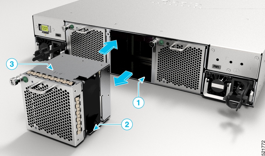
Field Replaceable Units
These components are field replaceable units (FRUs):
-
Chassis
-
Route Processor cards (Cisco ASR 9903 and Cisco ASR 9902 Router)
-
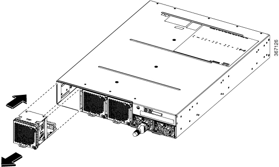
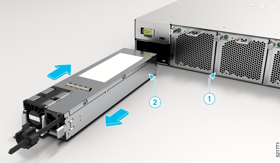
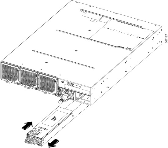
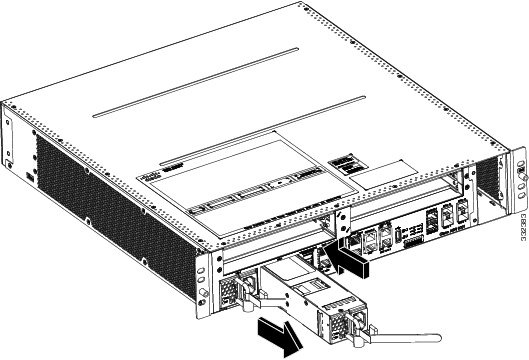
Power modules
-
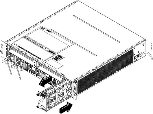
Fan tray
-
Transceiver modules
-
Modular port adapters (Cisco ASR 9001 Router)
-
Port Expansion Cards (PECs)
Online Insertion and Removal
Some field-replaceable units (FRUs) for the Cisco ASR 9000 Series Routers can be removed and replaced with the power on and the system operating. This facility is known as online insertion and removal (OIR). Unless otherwise noted, the maintenance tasks described in this chapter can be performed while the router remains powered on.
The following table displays the supported line cards, ports, and OIR duration for QDD-400G-ZR-S and QDD-400G-ZRP-S optical modules:
|
Line card |
Supported front panel ports |
Maximum supported OIR duration at mean sea level (MSL) with QDD-400G-ZR-S and QDD-400G-ZRP-S optical modules |
|---|---|---|
|
0, 7, 8, 12, 19 |
1 minute at 30°C (or 86°F) |
|
|
0, 7 |
3 minutes at 30°C (or 86°F) |
|
|
3, 5, 6, 7, 9 |
1 minute at 30°C (or 86°F) |
|
|
0, 4, 8, 12, 16 |
45 seconds at 30°C (or 86°F) |
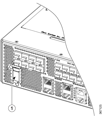
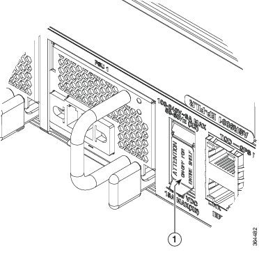
Powering Off the Router
 Caution |
Do not turn off the switch on the power tray to remove individual power modules. Power modules support OIR, so they can be removed and replaced with the power on and the system operating. |
If it becomes necessary to turn all power off to the router, follow these steps:
Procedure
|
Step 1 |
Set the power switch on the chassis to the off (0) position. 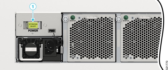
|
||
|
Step 2 |
Power off all circuit breakers for the source power lines connected to the power trays. |
||
|
Step 3 |
Verify that the Pwr OK indicator on each power module is off. |
||
|
Step 4 |
Verify that the OK indicator on the fan tray is off. |


 Feedback