LAN Switching Configuration Guide, Cisco IOS Release 15.0S
Bias-Free Language
The documentation set for this product strives to use bias-free language. For the purposes of this documentation set, bias-free is defined as language that does not imply discrimination based on age, disability, gender, racial identity, ethnic identity, sexual orientation, socioeconomic status, and intersectionality. Exceptions may be present in the documentation due to language that is hardcoded in the user interfaces of the product software, language used based on RFP documentation, or language that is used by a referenced third-party product. Learn more about how Cisco is using Inclusive Language.
- Updated:
- April 22, 2008
Chapter: Configuring Routing Between VLANs
- Finding Feature Information
- Contents
- Information About Routing Between VLANs
- Virtual Local Area Network Definition
- VLAN Colors
- Implementing VLANS
- Communication Between VLANs
- VLAN Interoperability
- Designing Switched VLANs
- Frame Tagging in ISL
- IEEE 802.1Q-in-Q VLAN Tag Termination on Subinterfaces
- Cisco 10000 Series Internet Router Application
- Security ACL Application on the Cisco 10000 Series Internet Router
- Unambiguous and Ambiguous Subinterfaces
- How to Configure Routing Between VLANS
- Configuring a VLAN Range
- Configuring Routing Between VLANs with Inter-Switch Link Encapsulation
- Configuring AppleTalk Routing over ISL
- Configuring Banyan VINES Routing over ISL
- Configuring DECnet Routing over ISL
- Configuring the Hot Standby Router Protocol over ISL
- Configuring IP Routing over TRISL
- Configuring IPX Routing on 802.10 VLANs over ISL
- Configuring IPX Routing over TRISL
- Configuring VIP Distributed Switching over ISL
- Configuring XNS Routing over ISL
- Configuring CLNS Routing over ISL
- Configuring IS-IS Routing over ISL
- Configuring Routing Between VLANs with IEEE 802.10 Encapsulation
- Configuring Routing Between VLANs with IEEE 802.1Q Encapsulation
- Configuring IEEE 802.1Q-in-Q VLAN Tag Termination
- Monitoring and Maintaining VLAN Subinterfaces
- Single Range Configuration: Example
- ISL Encapsulation Configuration: Examples
- AppleTalk Routing over ISL Configuration: Example
- Banyan VINES Routing over ISL Configuration: Example
- DECnet Routing over ISL Configuration: Example
- HSRP over ISL Configuration: Example
- IP Routing with RIF Between TrBRF VLANs: Example
- IP Routing Between a TRISL VLAN and an Ethernet ISL VLAN: Example
- IPX Routing over ISL Configuration: Example
- IPX Routing on FDDI Interfaces with SDE: Example
- Routing with RIF Between a TRISL VLAN and a Token Ring Interface: Example
- VIP Distributed Switching over ISL Configuration: Example
- XNS Routing over ISL Configuration: Example
- CLNS Routing over ISL Configuration: Example
- IS-IS Routing over ISL Configuration: Example
- Routing IEEE 802.10 Configuration: Example
- IEEE 802.1Q Encapsulation Configuration: Examples
- Configuring AppleTalk over IEEE 802.1Q: Example
- Configuring IP Routing over IEEE 802.1Q: Example
- Configuring IPX Routing over IEEE 802.1Q: Example
- VLAN 100 for Bridge Group 1 with Default VLAN1: Example
- VLAN 20 for Bridge Group 1 with Native VLAN: Example
- VLAN ISL or IEEE 802.1Q Routing: Example
- VLAN IEEE 802.1Q Bridging: Example
- VLAN IEEE 802.1Q IRB: Example
- Configuring IEEE 802.1Q-in-Q VLAN Tag Termination: Example
Configuring Routing Between VLANs
This module provides an overview of VLANs. It describes the encapsulation protocols used for routing between VLANs and provides some basic information about designing VLANs. This module contains tasks for configuring routing between VLANS.
Finding Feature Information
Your software release may not support all the features documented in this module. For the latest feature information and caveats, see the release notes for your platform and software release. To find information about the features documented in this module, and to see a list of the releases in which each feature is supported, see the "Feature Information for Routing Between VLANs" section.
Use Cisco Feature Navigator to find information about platform support and Cisco IOS and Catalyst OS software image support. To access Cisco Feature Navigator, go to http://www.cisco.com/go/cfn. An account on Cisco.com is not required.
Contents
•![]() Information About Routing Between VLANs
Information About Routing Between VLANs
•![]() How to Configure Routing Between VLANS
How to Configure Routing Between VLANS
•![]() Configuration Examples for Configuring Routing Between VLANs
Configuration Examples for Configuring Routing Between VLANs
•![]() Feature Information for Routing Between VLANs
Feature Information for Routing Between VLANs
Information About Routing Between VLANs
•![]() Virtual Local Area Network Definition
Virtual Local Area Network Definition
•![]() IEEE 802.1Q-in-Q VLAN Tag Termination on Subinterfaces
IEEE 802.1Q-in-Q VLAN Tag Termination on Subinterfaces
•![]() Cisco 10000 Series Internet Router Application
Cisco 10000 Series Internet Router Application
•![]() Security ACL Application on the Cisco 10000 Series Internet Router
Security ACL Application on the Cisco 10000 Series Internet Router
•![]() Unambiguous and Ambiguous Subinterfaces
Unambiguous and Ambiguous Subinterfaces
Virtual Local Area Network Definition
A virtual local area network (VLAN) is a switched network that is logically segmented on an organizational basis, by functions, project teams, or applications rather than on a physical or geographical basis. For example, all workstations and servers used by a particular workgroup team can be connected to the same VLAN, regardless of their physical connections to the network or the fact that they might be intermingled with other teams. Reconfiguration of the network can be done through software rather than by physically unplugging and moving devices or wires.
A VLAN can be thought of as a broadcast domain that exists within a defined set of switches. A VLAN consists of a number of end systems, either hosts or network equipment (such as bridges and routers), connected by a single bridging domain. The bridging domain is supported on various pieces of network equipment; for example, LAN switches that operate bridging protocols between them with a separate bridge group for each VLAN.
VLANs are created to provide the segmentation services traditionally provided by routers in LAN configurations. VLANs address scalability, security, and network management. Routers in VLAN topologies provide broadcast filtering, security, address summarization, and traffic flow management. None of the switches within the defined group will bridge any frames, not even broadcast frames, between two VLANs. Several key issues described in the following sections need to be considered when designing and building switched LAN internetworks:
•![]() Network Monitoring Using SNMP
Network Monitoring Using SNMP
•![]() Integrated Routing and Bridging
Integrated Routing and Bridging
LAN Segmentation
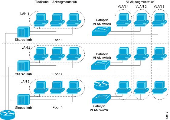
VLANs allow logical network topologies to overlay the physical switched infrastructure such that any arbitrary collection of LAN ports can be combined into an autonomous user group or community of interest. The technology logically segments the network into separate Layer 2 broadcast domains whereby packets are switched between ports designated to be within the same VLAN. By containing traffic originating on a particular LAN only to other LANs in the same VLAN, switched virtual networks avoid wasting bandwidth, a drawback inherent to traditional bridged and switched networks in which packets are often forwarded to LANs with no need for them. Implementation of VLANs also improves scalability, particularly in LAN environments that support broadcast- or multicast-intensive protocols and applications that flood packets throughout the network.
Figure 1 illustrates the difference between traditional physical LAN segmentation and logical VLAN segmentation.
Figure 1 LAN Segmentation and VLAN Segmentation
Security
VLANs improve security by isolating groups. High-security users can be grouped into a VLAN, possibly on the same physical segment, and no users outside that VLAN can communicate with them.
Broadcast Control
Just as switches isolate collision domains for attached hosts and only forward appropriate traffic out a particular port, VLANs provide complete isolation between VLANs. A VLAN is a bridging domain, and all broadcast and multicast traffic is contained within it.
VLAN Performance
The logical grouping of users allows an accounting group to make intensive use of a networked accounting system assigned to a VLAN that contains just that accounting group and its servers. That group's work will not affect other users. The VLAN configuration improves general network performance by not slowing down other users sharing the network.
Network Management
The logical grouping of users allows easier network management. It is not necessary to pull cables to move a user from one network to another. Adds, moves, and changes are achieved by configuring a port into the appropriate VLAN.
Network Monitoring Using SNMP
SNMP support has been added to provide mib-2 interfaces sparse table support for Fast Ethernet subinterfaces. Monitor your VLAN subinterface using the show vlans EXEC command. For more information on configuring SNMP on your Cisco network device or enabling an SNMP agent for remote access, see the "Configuring SNMP Support" module in the Cisco IOS Network Management Configuration Guide.
Communication Between VLANs
Communication between VLANs is accomplished through routing, and the traditional security and filtering functions of the router can be used. Cisco IOS software provides network services such as security filtering, quality of service (QoS), and accounting on a per-VLAN basis. As switched networks evolve to distributed VLANs, Cisco IOS software provides key inter-VLAN communications and allows the network to scale.
Before Cisco IOS Release 12.2, Cisco IOS support for interfaces that have 802.1Q encapsulation configured is IP, IP multicast, and IPX routing between respective VLANs represented as subinterfaces on a link. New functionality has been added in IEEE 802.1Q support for bridging on those interfaces and the capability to configure and use integrated routing and bridging (IRB).
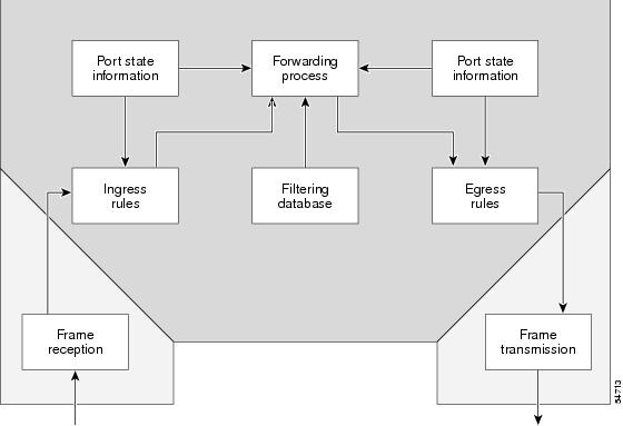
Relaying Function
The relaying function level, as displayed in Figure 2, is the lowest level in the architectural model described in the IEEE 802.1Q standard and presents three types of rules:
•![]() Ingress rules—Rules relevant to the classification of received frames belonging to a VLAN.
Ingress rules—Rules relevant to the classification of received frames belonging to a VLAN.
•![]() Forwarding rules between ports—Rules decide whether to filter or forward the frame.
Forwarding rules between ports—Rules decide whether to filter or forward the frame.
•![]() Egress rules (output of frames from the switch)—Rules decide if the frame must be sent tagged or untagged.
Egress rules (output of frames from the switch)—Rules decide if the frame must be sent tagged or untagged.
Figure 2 Relaying Function
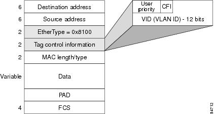
The Tagging Scheme
Figure 3 shows the tagging scheme proposed by the 802.3ac standard, that is, the addition of the four octets after the source MAC address. Their presence is indicated by a particular value of the EtherType field (called TPID), which has been fixed to be equal to 0x8100. When a frame has the EtherType equal to 0x8100, this frame carries the tag IEEE 802.1Q/802.1p. The tag is stored in the following two octets and it contains 3 bits of user priority, 1 bit of Canonical Format Identifier (CFI), and 12 bits of VLAN ID (VID). The 3 bits of user priority are used by the 802.1p standard; the CFI is used for compatibility reasons between Ethernet-type networks and Token Ring-type networks. The VID is the identification of the VLAN, which is basically used by the 802.1Q standard; being on 12 bits, it allows the identification of 4096 VLANs.
After the two octets of TPID and the two octets of the Tag Control Information field there are two octets that originally would have been located after the Source Address field where there is the TPID. They contain either the MAC length in the case of IEEE 802.3 or the EtherType in the case of Ethernet version 2.
Figure 3 Tagging Scheme
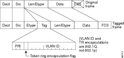
The EtherType and VLAN ID are inserted after the MAC source address, but before the original Ethertype/Length or Logical Link Control (LLC). The 1-bit CFI included a T-R Encapsulation bit so that Token Ring frames can be carried across Ethernet backbones without using 802.1H translation.
Frame Control Sequence Recomputation
Figure 4 shows how adding a tag in a frame recomputes the Frame Control Sequence. 802.1p and 802.1Q share the same tag.
Figure 4 Adding a Tag Recomputes the Frame Control Sequence
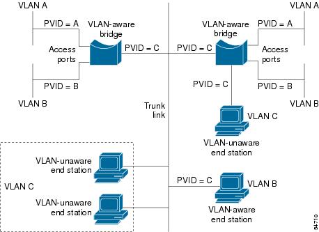
Native VLAN
Each physical port has a parameter called PVID. Every 802.1Q port is assigned a PVID value that is of its native VLAN ID (default is VLAN 1). All untagged frames are assigned to the LAN specified in the PVID parameter. When a tagged frame is received by a port, the tag is respected. If the frame is untagged, the value contained in the PVID is considered as a tag. Because the frame is untagged and the PVID is tagged to allow the coexistence, as shown in Figure 5, on the same pieces of cable of VLAN-aware bridge/stations and of VLAN-unaware bridges/stations. Consider, for example, the two stations connected to the central trunk link in the lower part of Figure 5. They are VLAN-unaware and they will be associated to the VLAN C, because the PVIDs of the VLAN-aware bridges are equal to VLAN C. Because the VLAN-unaware stations will send only untagged frames, when the VLAN-aware bridge devices receive these untagged frames they will assign them to VLAN C.
Figure 5 Native VLAN
PVST+
PVST+ provides support for 802.1Q trunks and the mapping of multiple spanning trees to the single spanning tree of 802.1Q switches.
The PVST+ architecture distinguishes three types of regions:
•![]() A PVST region
A PVST region
•![]() A PVST+ region
A PVST+ region
•![]() A MST region
A MST region
Each region consists of a homogenous type of switch. A PVST region can be connected to a PVST+ region by connecting two ISL ports. Similarly, a PVST+ region can be connected to an MST region by connecting two 802.1Q ports.
At the boundary between a PVST region and a PVST+ region the mapping of spanning trees is one-to-one. At the boundary between a MST region and a PVST+ region, the ST in the MST region maps to one PVST in the PVST+ region. The one it maps to is called the common spanning tree (CST). The default CST is the PVST of VLAN 1 (Native VLAN).
All PVSTs, except for the CST, are tunneled through the MST region. Tunneling means that bridge protocol data units (BPDUs) are flooded through the MST region along the single spanning tree present in the MST region.
Ingress and Egress Rules
The BPDU transmission on the 802.1Q port of a PVST+ router will be implemented in compliance with the following rules:
•![]() The CST BPDU (of VLAN 1, by default) is sent to the IEEE address.
The CST BPDU (of VLAN 1, by default) is sent to the IEEE address.
•![]() All the other BPDUs are sent to Shared Spanning Tree Protocol (SSTP)-Address and encapsulated with Logical Link Control-Subnetwork Access Protocol (LLC-SNAP) header.
All the other BPDUs are sent to Shared Spanning Tree Protocol (SSTP)-Address and encapsulated with Logical Link Control-Subnetwork Access Protocol (LLC-SNAP) header.
•![]() The BPDU of the CST and BPDU of the VLAN equal to the PVID of the 802.1Q trunk are sent untagged.
The BPDU of the CST and BPDU of the VLAN equal to the PVID of the 802.1Q trunk are sent untagged.
•![]() All other BPDUs are sent tagged with the VLAN ID.
All other BPDUs are sent tagged with the VLAN ID.
•![]() The CST BPDU is also sent to the SSTP address.
The CST BPDU is also sent to the SSTP address.
•![]() Each SSTP-addressed BPDU is also tailed by a Tag-Length-Value for the PVID checking.
Each SSTP-addressed BPDU is also tailed by a Tag-Length-Value for the PVID checking.
The BPDU reception on the 802.1Q port of a PVST+ router will follow these rules:
•![]() All untagged IEEE addressed BPDUs must be received on the PVID of the 802.1Q port.
All untagged IEEE addressed BPDUs must be received on the PVID of the 802.1Q port.
•![]() The IEEE addressed BPDUs whose VLAN ID matches the Native VLAN are processed by CST.
The IEEE addressed BPDUs whose VLAN ID matches the Native VLAN are processed by CST.
•![]() All the other IEEE addressed BPDUs whose VLAN ID does not match the Native VLAN and whose port type is not of 802.1Q are processed by the spanning tree of that particular VLAN ID.
All the other IEEE addressed BPDUs whose VLAN ID does not match the Native VLAN and whose port type is not of 802.1Q are processed by the spanning tree of that particular VLAN ID.
•![]() The SSTP addressed BPDU whose VLAN ID is not equal to the TLV are dropped and the ports are blocked for inconsistency.
The SSTP addressed BPDU whose VLAN ID is not equal to the TLV are dropped and the ports are blocked for inconsistency.
•![]() All the other SSTP addressed BPDUs whose VLAN ID is not equal to the Native VLAN are processed by the spanning tree of that particular VLAN ID.
All the other SSTP addressed BPDUs whose VLAN ID is not equal to the Native VLAN are processed by the spanning tree of that particular VLAN ID.
•![]() The SSTP addressed BPDUs whose VLAN ID is equal to the Native VLAN are dropped. It is used for consistency checking.
The SSTP addressed BPDUs whose VLAN ID is equal to the Native VLAN are dropped. It is used for consistency checking.
Integrated Routing and Bridging
IRB enables a user to route a given protocol between routed interfaces and bridge groups or route a given protocol between the bridge groups. Integrated routing and bridging is supported on the following protocols:
•![]() IP
IP
•![]() IPX
IPX
•![]() AppleTalk
AppleTalk
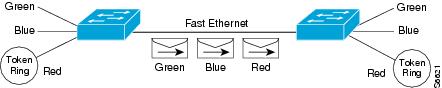
VLAN Colors
VLAN switching is accomplished through frame tagging where traffic originating and contained within a particular virtual topology carries a unique VLAN ID as it traverses a common backbone or trunk link. The VLAN ID enables VLAN switching devices to make intelligent forwarding decisions based on the embedded VLAN ID. Each VLAN is differentiated by a color, or VLAN identifier. The unique VLAN ID determines the frame coloring for the VLAN. Packets originating and contained within a particular VLAN carry the identifier that uniquely defines that VLAN (by the VLAN ID).
The VLAN ID allows VLAN switches and routers to selectively forward packets to ports with the same VLAN ID. The switch that receives the frame from the source station inserts the VLAN ID and the packet is switched onto the shared backbone network. When the frame exits the switched LAN, a switch strips the header and forwards the frame to interfaces that match the VLAN color. If you are using a Cisco network management product such as VlanDirector, you can actually color code the VLANs and monitor VLAN graphically.
Implementing VLANS
Network managers can logically group networks that span all major topologies, including high-speed technologies such as, ATM, FDDI, and Fast Ethernet. By creating virtual LANs, system and network administrators can control traffic patterns and react quickly to relocations and keep up with constant changes in the network due to moving requirements and node relocation just by changing the VLAN member list in the router configuration. They can add, remove, or move devices or make other changes to network configuration using software to make the changes.
Issues regarding creating VLANs should have been addressed when you developed your network design. Issues to consider include the following:
•![]() Scalability
Scalability
•![]() Performance improvements
Performance improvements
•![]() Security
Security
•![]() Network additions, moves, and changes
Network additions, moves, and changes
Communication Between VLANs
Cisco IOS software provides full-feature routing at Layer 3 and translation at Layer 2 between VLANs. Five different protocols are available for routing between VLANs:
•![]() ATM LANE Fast Simple Server Replication Protocol
ATM LANE Fast Simple Server Replication Protocol
All five of these technologies are based on OSI Layer 2 bridge multiplexing mechanisms.
Inter-Switch Link Protocol
The Inter-Switch Link (ISL) protocol is used to interconnect two VLAN-capable Ethernet, Fast Ethernet, or Gigabit Ethernet devices, such as the Catalyst 3000 or 5000 switches and Cisco 7500 routers. The ISL protocol is a packet-tagging protocol that contains a standard Ethernet frame and the VLAN information associated with that frame. The packets on the ISL link contain a standard Ethernet, FDDI, or Token Ring frame and the VLAN information associated with that frame. ISL is currently supported only over Fast Ethernet links, but a single ISL link, or trunk, can carry different protocols from multiple VLANs.
Procedures for configuring ISL and Token Ring ISL (TRISL) features are provided in "Configuring Routing Between VLANs with Inter-Switch Link Encapsulation" section.
IEEE 802.10 Protocol
The IEEE 802.10 protocol provides connectivity between VLANs. Originally developed to address the growing need for security within shared LAN/MAN environments, it incorporates authentication and encryption techniques to ensure data confidentiality and integrity throughout the network. Additionally, by functioning at Layer 2, it is well suited to high-throughput, low-latency switching environments. The IEEE 802.10 protocol can run over any LAN or HDLC serial interface.
Procedures for configuring routing between VLANs with IEEE 802.10 encapsulation are provided in the "Configuring Routing Between VLANs with IEEE 802.10 Encapsulation" section.
IEEE 802.1Q Protocol
The IEEE 802.1Q protocol is used to interconnect multiple switches and routers, and for defining VLAN topologies. Cisco currently supports IEEE 802.1Q for Fast Ethernet and Gigabit Ethernet interfaces.

Note ![]() Cisco does not support IEEE 802.1Q encapsulation for Ethernet interfaces.
Cisco does not support IEEE 802.1Q encapsulation for Ethernet interfaces.
Procedures for configuring routing between VLANs with IEEE 802.1Q encapsulation are provided in the "Configuring Routing Between VLANs with IEEE 802.1Q Encapsulation" section.
ATM LANE Protocol
The ATM LAN Emulation (LANE) protocol provides a way for legacy LAN users to take advantage of ATM benefits without requiring modifications to end-station hardware or software. LANE emulates a broadcast environment like IEEE 802.3 Ethernet on top of an ATM network that is a point-to-point environment.
LANE makes ATM function like a LAN. LANE allows standard LAN drivers like NDIS and ODI to be used. The virtual LAN is transparent to applications. Applications can use normal LAN functions without the underlying complexities of the ATM implementation. For example, a station can send broadcasts and multicasts, even though ATM is defined as a point-to-point technology and does not support any-to-any services.
To accomplish this, special low-level software is implemented on an ATM client workstation, called the LAN Emulation Client (LEC). The client software communicates with a central control point called a LAN Emulation Server (LES). A broadcast and unknown server (BUS) acts as a central point to distribute broadcasts and multicasts. The LAN Emulation Configuration Server (LECS) holds a database of LECs and the ELANs they belong to. The database is maintained by a network administrator.
These protocols are described in detail in the Cisco Internetwork Design Guide.
ATM LANE Fast Simple Server Replication Protocol
To improve the ATM LANE Simple Server Replication Protocol (SSRP), Cisco introduced the ATM LANE Fast Simple Server Replication Protocol (FSSRP). FSSRP differs from LANE SSRP in that all configured LANE servers of an ELAN are always active. FSSRP-enabled LANE clients have virtual circuits (VCs) established to a maximum of four LANE servers and BUSs at one time. If a single LANE server goes down, the LANE client quickly switches over to the next LANE server and BUS, resulting in no data or LE ARP table entry loss and no extraneous signalling.
The FSSRP feature improves upon SSRP such that LANE server and BUS switchover for LANE clients is immediate. With SSRP, a LANE server would go down, and depending on the network load, it may have taken considerable time for the LANE client to come back up joined to the correct LANE server and BUS. In addition to going down with SSRP, the LANE client would do the following:
•![]() Clear out its data direct VCs
Clear out its data direct VCs
•![]() Clear out its LE ARP entries
Clear out its LE ARP entries
•![]() Cause substantial signalling activity and data loss
Cause substantial signalling activity and data loss
FSSRP was designed to alleviate these problems with the LANE client. With FSSRP, each LANE client is simultaneously joined to up to four LANE servers and BUSs. The concept of the master LANE server and BUS is maintained; the LANE client uses the master LANE server when it needs LANE server BUS services. However, the difference between SSRP and FSSRP is that if and when the master LANE server goes down, the LANE client is already connected to multiple backup LANE servers and BUSs. The LANE client simply uses the next backup LANE server and BUS as the master LANE server and BUS.
VLAN Interoperability
Cisco IOS features bring added benefits to the VLAN technology. Enhancements to ISL, IEEE 802.10, and ATM LANE implementations enable routing of all major protocols between VLANs. These enhancements allow users to create more robust networks incorporating VLAN configurations by providing communications capabilities between VLANs.
Inter-VLAN Communications
The Cisco IOS supports full routing of several protocols over ISL and ATM LANE VLANs. IP, Novell IPX, and AppleTalk routing are supported over IEEE 802.10 VLANs. Standard routing attributes such as network advertisements, secondaries, and help addresses are applicable, and VLAN routing is fast switched. Table 1 shows protocols supported for each VLAN encapsulation format and corresponding Cisco IOS software releases in which support was introduced.
VLAN Translation
VLAN translation refers to the ability of the Cisco IOS software to translate between different VLANs or between VLAN and non-VLAN encapsulating interfaces at Layer 2. Translation is typically used for selective inter-VLAN switching of nonroutable protocols and to extend a single VLAN topology across hybrid switching environments. It is also possible to bridge VLANs on the main interface; the VLAN encapsulating header is preserved. Topology changes in one VLAN domain do not affect a different VLAN.
Designing Switched VLANs
By the time you are ready to configure routing between VLANs, you will have already defined them through the switches in your network. Issues related to network design and VLAN definition should be addressed during your network design. See the Cisco Internetwork Design Guide and the appropriate switch documentation for information on these topics:
•![]() Sharing resources between VLANs
Sharing resources between VLANs
•![]() Load balancing
Load balancing
•![]() Redundant links
Redundant links
•![]() Addressing
Addressing
•![]() Segmenting networks with VLANs—Segmenting the network into broadcast groups improves network security. Use router access lists based on station addresses, application types, and protocol types.
Segmenting networks with VLANs—Segmenting the network into broadcast groups improves network security. Use router access lists based on station addresses, application types, and protocol types.
•![]() Routers and their role in switched networks—In switched networks, routers perform broadcast management, route processing, and distribution, and provide communication between VLANs. Routers provide VLAN access to shared resources and connect to other parts of the network that are either logically segmented with the more traditional subnet approach or require access to remote sites across wide-area links.
Routers and their role in switched networks—In switched networks, routers perform broadcast management, route processing, and distribution, and provide communication between VLANs. Routers provide VLAN access to shared resources and connect to other parts of the network that are either logically segmented with the more traditional subnet approach or require access to remote sites across wide-area links.
Frame Tagging in ISL
ISL is a Cisco protocol for interconnecting multiple switches and maintaining VLAN information as traffic goes between switches. ISL provides VLAN capabilities while maintaining full wire speed performance on Fast Ethernet links in full- or half-duplex mode. ISL operates in a point-to-point environment and will support up to 1000 VLANs. You can define virtually as many logical networks as are necessary for your environment.
With ISL, an Ethernet frame is encapsulated with a header that transports VLAN IDs between switches and routers. A 26-byte header that contains a 10-bit VLAN ID is propounded to the Ethernet frame.
A VLAN ID is added to the frame only when the frame is prepended for a nonlocal network. Figure 6 shows VLAN packets traversing the shared backbone. Each VLAN packet carries the VLAN ID within the packet header.
Figure 6 VLAN Packets Traversing the Shared Backbone
You can configure routing between any number of VLANs in your network. This section documents the configuration tasks for each protocol supported with ISL encapsulation. The basic process is the same, regardless of the protocol being routed. It involves the following tasks:
•![]() Enabling the protocol on the router
Enabling the protocol on the router
•![]() Enabling the protocol on the interface
Enabling the protocol on the interface
•![]() Defining the encapsulation format as ISL or TRISL
Defining the encapsulation format as ISL or TRISL
•![]() Customizing the protocol according to the requirements for your environment
Customizing the protocol according to the requirements for your environment
IEEE 802.1Q-in-Q VLAN Tag Termination on Subinterfaces
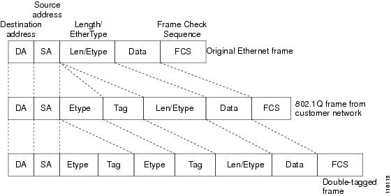
IEEE 802.1Q-in-Q VLAN Tag Termination simply adds another layer of IEEE 802.1Q tag (called "metro tag" or "PE-VLAN") to the 802.1Q tagged packets that enter the network. The purpose is to expand the VLAN space by tagging the tagged packets, thus producing a "double-tagged" frame. The expanded VLAN space allows the service provider to provide certain services, such as Internet access on specific VLANs for specific customers, and yet still allows the service provider to provide other types of services for their other customers on other VLANs.
Generally the service provider's customers require a range of VLANs to handle multiple applications. Service providers can allow their customers to use this feature to safely assign their own VLAN IDs on subinterfaces because these subinterface VLAN IDs are encapsulated within a service-provider designated VLAN ID for that customer. Therefore there is no overlap of VLAN IDs among customers, nor does traffic from different customers become mixed. The double-tagged frame is "terminated" or assigned on a subinterface with an expanded encapsulation dot1q command that specifies the two VLAN ID tags (outer VLAN ID and inner VLAN ID) terminated on the subinterface. See Figure 7.
IEEE 802.1Q-in-Q VLAN Tag Termination is generally supported on whichever Cisco IOS features or protocols are supported on the subinterface; the exception is that Cisco 10000 series Internet router only supports PPPoE. For example if you can run PPPoE on the subinterface, you can configure a double-tagged frame for PPPoE. The only restriction is whether you assign ambiguous or unambiguous subinterfaces for the inner VLAN ID. See the "Perform these tasks to configure the main interface used for the Q-in-Q double tagging and to configure the subinterfaces." section.
Note ![]() The Cisco 10000 series Internet router only supports PPPoE over Q-in-Q (PPPoEQinQ).
The Cisco 10000 series Internet router only supports PPPoE over Q-in-Q (PPPoEQinQ).
The primary benefit for the service provider is reduced number of VLANs supported for the same number of customers. Other benefits of this feature include:
•![]() PPPoE scalability. By expanding the available VLAN space from 4096 to approximately 16.8 million (4096 times 4096), the number of PPPoE sessions that can be terminated on a given interface is multiplied.
PPPoE scalability. By expanding the available VLAN space from 4096 to approximately 16.8 million (4096 times 4096), the number of PPPoE sessions that can be terminated on a given interface is multiplied.
•![]() When deploying Gigabyte Ethernet DSL Access Multiplexer (DSLAM) in wholesale model, you can assign the inner VLAN ID to represent the end-customer virtual circuit (VC) and assign the outer VLAN ID to represent the service provider ID.
When deploying Gigabyte Ethernet DSL Access Multiplexer (DSLAM) in wholesale model, you can assign the inner VLAN ID to represent the end-customer virtual circuit (VC) and assign the outer VLAN ID to represent the service provider ID.
The Q-in-Q VLAN tag termination feature is simpler than the IEEE 802.1Q tunneling feature deployed for the Catalyst 6500 series switches or the Catalyst 3550 and Catalyst 3750 switches. Whereas switches require IEEE 802.1Q tunnels on interfaces to carry double-tagged traffic, routers need only encapsulate Q-in-Q VLAN tags within another level of 802.1Q tags in order for the packets to arrive at the correct destination as shown in Figure 7.
Figure 7 Untagged, 802.1Q-Tagged, and Double-Tagged Ethernet Frames
Cisco 10000 Series Internet Router Application
For the emerging broadband Ethernet-based DSLAM market, the Cisco 10000 series Internet router supports Q-in-Q encapsulation. With the Ethernet-based DSLAM model shown in Figure 8, customers typically get their own VLAN and all these VLANs are aggregated on a DSLAM.
Figure 8
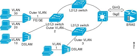
Broadband Ethernet-based DSLAM Model of Q-in-Q VLANs
VLAN aggregation on a DSLAM will result in a lot of aggregate VLANs that at some point need to be terminated on the broadband remote access servers (BRAS). Although the model could connect the DSLAMs directly to the BRAS, a more common model uses the existing Ethernet-switched network where each DSLAM VLAN ID is tagged with a second tag (Q-in-Q) as it connects into the Ethernet-switched network.
The only model that is supported is PPPoE over Q-in-Q (PPPoEoQinQ). This can either be a PPP terminated session or as a L2TP LAC session. No IP over Q-in-Q is supported.
The Cisco 10000 series Internet router already supports plain PPPoE and PPP over 802.1Q encapsulation. Supporting PPP over Q-in-Q encapsulation is new. PPP over Q-in-Q encapsulation processing is an extension to 802.1q encapsulation processing. A Q-in-Q frame looks like a VLAN 802.1Q frame, only it has two 802.1Q tags instead of one. See Figure 7.
PPP over Q-in-Q encapsulation supports configurable outer tag Ethertype. The configurable Ethertype field values are 0x8100 (default), 0x9100, and 0x9200. See Figure 9.
Figure 9

Supported Configurable Ethertype Field Values
Security ACL Application on the Cisco 10000 Series Internet Router
The IEEE 802.1Q-in-Q VLAN Tag Termination feature provides limited security access control list (ACL) support for the Cisco 10000 series Internet router.
If you apply an ACL to PPPoE traffic on a Q-in-Q subinterface in a VLAN, apply the ACL directly on the PPPoE session, using virtual access interfaces (VAIs) or RADIUS attribute 11 or 242.
You can apply ACLs to virtual access interfaces by configuring them under virtual template interfaces. You can also configure ACLs by using RADIUS attribute 11 or 242. When you use attribute 242, a maximum of 30,000 sessions can have ACLs.
ACLs that are applied to the VLAN Q-in-Q subinterface have no effect and are silently ignored. In the following example, ACL 1 that is applied to the VLAN Q-in-Q subinterface level will be ignored:
Router(config)# interface FastEthernet3/0/0.100
Router(config-subif)# encapsulation dot1q 100 second-dot1q 200
Router(config-subif)# ip access-group 1
Unambiguous and Ambiguous Subinterfaces
The encapsulation dot1q command is used to configure Q-in-Q termination on a subinterface. The command accepts an Outer VLAN ID and one or more Inner VLAN IDs. The outer VLAN ID always has a specific value, while inner VLAN ID can either be a specific value or a range of values.
A subinterface that is configured with a single Inner VLAN ID is called an unambiguous Q-in-Q subinterface. In the following example, Q-in-Q traffic with an Outer VLAN ID of 101 and an Inner VLAN ID of 1001 is mapped to the Gigabit Ethernet 1/0.100 subinterface:
Router(config)# interface gigabitEehernet1/0.100
Router(config-subif)# encapsulation dot1q 101 second-dot1q 1001
A subinterface that is configured with multiple Inner VLAN IDs is called an ambiguous Q-in-Q subinterface. By allowing multiple Inner VLAN IDs to be grouped together, ambiguous Q-in-Q subinterfaces allow for a smaller configuration, improved memory usage and better scalability.
In the following example, Q-in-Q traffic with an Outer VLAN ID of 101 and Inner VLAN IDs anywhere in the 2001-2100 and 3001-3100 range is mapped to the Gigabit Ethernet 1/0.101 subinterface.:
Router(config)# interface gigabitethernet1/0.101
Router(config-subif)# encapsulation dot1q 101 second-dot1q 2001-2100,3001-3100
Ambiguous subinterfaces can also use the any keyword to specify the inner VLAN ID.
See the "Monitoring and Maintaining VLAN Subinterfaces" section for an example of how VLAN IDs are assigned to subinterfaces, and for a detailed example of how the any keyword is used on ambiguous subinterfaces.
Only PPPoE is supported on ambiguous subinterfaces. Standard IP routing is not supported on ambiguous subinterfaces.
Note ![]() On the Cisco 10000 series Internet router, Modular QoS services are only supported on unambiguous subinterfaces.
On the Cisco 10000 series Internet router, Modular QoS services are only supported on unambiguous subinterfaces.
How to Configure Routing Between VLANS
•![]() Configuring Routing Between VLANs with Inter-Switch Link Encapsulation
Configuring Routing Between VLANs with Inter-Switch Link Encapsulation
•![]() Configuring Routing Between VLANs with IEEE 802.10 Encapsulation
Configuring Routing Between VLANs with IEEE 802.10 Encapsulation
•![]() Configuring Routing Between VLANs with IEEE 802.1Q Encapsulation
Configuring Routing Between VLANs with IEEE 802.1Q Encapsulation
•![]() Configuring IEEE 802.1Q-in-Q VLAN Tag Termination
Configuring IEEE 802.1Q-in-Q VLAN Tag Termination
Configuring a VLAN Range
Using the VLAN Range feature, you can group VLAN subinterfaces together so that any command entered in a group applies to every subinterface within the group. This capability simplifies configurations and reduces command parsing.
The VLAN Range feature provides the following benefits:
•![]() Simultaneous Configurations: Identical commands can be entered once for a range of subinterfaces, rather than being entered separately for each subinterface.
Simultaneous Configurations: Identical commands can be entered once for a range of subinterfaces, rather than being entered separately for each subinterface.
•![]() Overlapping Range Configurations: Overlapping ranges of subinterfaces can be configured.
Overlapping Range Configurations: Overlapping ranges of subinterfaces can be configured.
•![]() Customized Subinterfaces: Individual subinterfaces within a range can be customized or deleted.
Customized Subinterfaces: Individual subinterfaces within a range can be customized or deleted.
Restrictions
•![]() Each command you enter while you are in interface configuration mode with the interface range command is executed as it is entered. The commands are not batched together for execution after you exit interface configuration mode. If you exit interface configuration mode while the commands are being executed, some commands might not be executed on some interfaces in the range. Wait until the command prompt reappears before exiting interface configuration mode.
Each command you enter while you are in interface configuration mode with the interface range command is executed as it is entered. The commands are not batched together for execution after you exit interface configuration mode. If you exit interface configuration mode while the commands are being executed, some commands might not be executed on some interfaces in the range. Wait until the command prompt reappears before exiting interface configuration mode.
•![]() The no interface range command is not supported. You must delete individual subinterfaces to delete a range.
The no interface range command is not supported. You must delete individual subinterfaces to delete a range.
Configuring a Range of VLAN Subinterfaces
Use the following commands to configure a range of VLAN subinterfaces.
SUMMARY STEPS
1. ![]() enable
enable
2. ![]() configure terminal
configure terminal
3. ![]() interface range {{ethernet | fastethernet | gigabitethernet | atm} slot/interface.subinterface - {{ethernet | fastethernet | gigabitethernet | atm} slot/interface.subinterface}]
interface range {{ethernet | fastethernet | gigabitethernet | atm} slot/interface.subinterface - {{ethernet | fastethernet | gigabitethernet | atm} slot/interface.subinterface}]
4. ![]() encapsulation dot1Q vlan-id
encapsulation dot1Q vlan-id
5. ![]() no shutdown
no shutdown
6. ![]() exit
exit
7. ![]() show running-config
show running-config
8. ![]() show interfaces
show interfaces
DETAILED STEPS
Configuring Routing Between VLANs with Inter-Switch Link Encapsulation
This section describes the Inter-Switch Link (ISL) protocol and provides guidelines for configuring ISL and Token Ring ISL (TRISL) features. This section contains the following:
•![]() Configuring AppleTalk Routing over ISL
Configuring AppleTalk Routing over ISL
•![]() Configuring Banyan VINES Routing over ISL
Configuring Banyan VINES Routing over ISL
•![]() Configuring DECnet Routing over ISL
Configuring DECnet Routing over ISL
•![]() Configuring the Hot Standby Router Protocol over ISL
Configuring the Hot Standby Router Protocol over ISL
•![]() Configuring IP Routing over TRISL
Configuring IP Routing over TRISL
•![]() Configuring IPX Routing on 802.10 VLANs over ISL
Configuring IPX Routing on 802.10 VLANs over ISL
•![]() Configuring IPX Routing over TRISL
Configuring IPX Routing over TRISL
•![]() Configuring VIP Distributed Switching over ISL
Configuring VIP Distributed Switching over ISL
•![]() Configuring XNS Routing over ISL
Configuring XNS Routing over ISL
•![]() Configuring CLNS Routing over ISL
Configuring CLNS Routing over ISL
•![]() Configuring IS-IS Routing over ISL
Configuring IS-IS Routing over ISL
Configuring AppleTalk Routing over ISL
AppleTalk can be routed over VLAN subinterfaces using the ISL and IEEE 802.10 VLAN encapsulation protocols. The AppleTalk Routing over ISL and IEEE 802.10 Virtual LANs feature provides full-feature Cisco IOS software AppleTalk support on a per-VLAN basis, allowing standard AppleTalk capabilities to be configured on VLANs.
To route AppleTalk over ISL or IEEE 802.10 between VLANs, you need to customize the subinterface to create the environment in which it will be used. Perform the steps in the order in which they appear.
SUMMARY STEPS
1. ![]() enable
enable
2. ![]() configure terminal
configure terminal
3. ![]() appletalk routing [eigrp router-number]
appletalk routing [eigrp router-number]
4. ![]() interface type slot/port.subinterface-number
interface type slot/port.subinterface-number
5. ![]() encapsulation isl vlan-identifier
encapsulation isl vlan-identifier
or
encapsulation sde said
6. ![]() appletalk cable-range cable-range [network.node]
appletalk cable-range cable-range [network.node]
7. ![]() appletalk zone zone-name
appletalk zone zone-name
DETAILED STEPS
Configuring Banyan VINES Routing over ISL
Banyan VINES can be routed over VLAN subinterfaces using the ISL encapsulation protocol. The Banyan VINES Routing over ISL Virtual LANs feature provides full-feature Cisco IOS software Banyan VINES support on a per-VLAN basis, allowing standard Banyan VINES capabilities to be configured on VLANs.
To route Banyan VINES over ISL between VLANs, you need to configure ISL encapsulation on the subinterface. Perform the steps in the following task in the order in which they appear:
SUMMARY STEPS
1. ![]() enable
enable
2. ![]() configure terminal
configure terminal
3. ![]() vines routing [address]
vines routing [address]
4. ![]() interface type slot/port.subinterface-number
interface type slot/port.subinterface-number
5. ![]() encapsulation isl vlan-identifier
encapsulation isl vlan-identifier
6. ![]() vines metric [whole [fraction]]
vines metric [whole [fraction]]
DETAILED STEPS
Configuring DECnet Routing over ISL
DECnet can be routed over VLAN subinterfaces using the ISL VLAN encapsulation protocols. The DECnet Routing over ISL Virtual LANs feature provides full-feature Cisco IOS software DECnet support on a per-VLAN basis, allowing standard DECnet capabilities to be configured on VLANs.
To route DECnet over ISL VLANs, you need to configure ISL encapsulation on the subinterface. Perform the steps described in the following task in the order in which they appear.
SUMMARY STEPS
1. ![]() enable
enable
2. ![]() configure terminal
configure terminal
3. ![]() decnet [network-number] routing [decnet-address]
decnet [network-number] routing [decnet-address]
4. ![]() interface type slot/port.subinterface-number
interface type slot/port.subinterface-number
5. ![]() encapsulation isl vlan-identifier
encapsulation isl vlan-identifier
6. ![]() decnet cost [cost-value]
decnet cost [cost-value]
DETAILED STEPS
Configuring the Hot Standby Router Protocol over ISL
The Hot Standby Router Protocol (HSRP) provides fault tolerance and enhanced routing performance for IP networks. HSRP allows Cisco IOS routers to monitor each other's operational status and very quickly assume packet forwarding responsibility in the event the current forwarding device in the HSRP group fails or is taken down for maintenance. The standby mechanism remains transparent to the attached hosts and can be deployed on any LAN type. With multiple Hot Standby groups, routers can simultaneously provide redundant backup and perform loadsharing across different IP subnets.
Figure 10 illustrates HSRP in use with ISL providing routing between several VLANs.
Figure 10 Hot Standby Router Protocol in VLAN Configurations
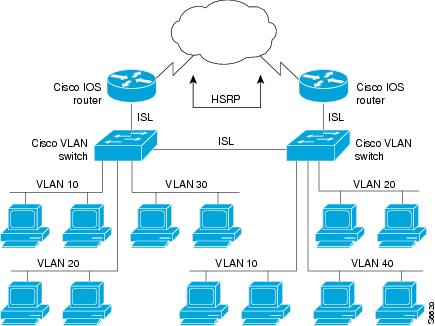
A separate HSRP group is configured for each VLAN subnet so that Cisco IOS router A can be the primary and forwarding router for VLANs 10 and 20. At the same time, it acts as backup for VLANs 30 and 40. Conversely, Router B acts as the primary and forwarding router for ISL VLANs 30 and 40, as well as the secondary and backup router for distributed VLAN subnets 10 and 20.
Running HSRP over ISL allows users to configure redundancy between multiple routers that are configured as front ends for VLAN IP subnets. By configuring HSRP over ISLs, users can eliminate situations in which a single point of failure causes traffic interruptions. This feature inherently provides some improvement in overall networking resilience by providing load balancing and redundancy capabilities between subnets and VLANs.
To configure HSRP over ISLs between VLANs, you need to create the environment in which it will be used. Perform the tasks described in the following sections in the order in which they appear.
SUMMARY STEPS
1. ![]() enable
enable
2. ![]() configure terminal
configure terminal
3. ![]() interface type slot/port.subinterface-number
interface type slot/port.subinterface-number
4. ![]() encapsulation isl vlan-identifier
encapsulation isl vlan-identifier
5. ![]() ip address ip-address mask [secondary]
ip address ip-address mask [secondary]
6. ![]() standby [group-number] ip [ip-address [secondary]]
standby [group-number] ip [ip-address [secondary]]
7. ![]() standby [group-number] timers hellotime holdtime
standby [group-number] timers hellotime holdtime
8. ![]() standby [group-number] priority priority
standby [group-number] priority priority
9. ![]() standby [group-number] preempt
standby [group-number] preempt
10. ![]() standby [group-number] track type-number [interface-priority]
standby [group-number] track type-number [interface-priority]
11. ![]() standby [group-number] authentication string
standby [group-number] authentication string
DETAILED STEPS
Note ![]() For more information on HSRP, see the "Configuring HSRP" module in the Cisco IOS IP Application Services Configuration Guide.
For more information on HSRP, see the "Configuring HSRP" module in the Cisco IOS IP Application Services Configuration Guide.
Configuring IP Routing over TRISL
The IP routing over TRISL VLANs feature extends IP routing capabilities to include support for routing IP frame types in VLAN configurations.
SUMMARY STEPS
1. ![]() enable
enable
2. ![]() configure terminal
configure terminal
3. ![]() ip routing
ip routing
4. ![]() interface type slot/port.subinterface-number
interface type slot/port.subinterface-number
5. ![]() encapsulation tr-isl trbrf-vlan vlanid bridge-num bridge-number
encapsulation tr-isl trbrf-vlan vlanid bridge-num bridge-number
6. ![]() ip address ip-address mask
ip address ip-address mask
DETAILED STEPS
Configuring IPX Routing on 802.10 VLANs over ISL
The IPX Encapsulation for 802.10 VLAN feature provides configurable IPX (Novell-FDDI, SAP, SNAP) encapsulation over 802.10 VLAN on router FDDI interfaces to connect the Catalyst 5000 VLAN switch. This feature extends Novell NetWare routing capabilities to include support for routing all standard IPX encapsulations for Ethernet frame types in VLAN configurations. Users with Novell NetWare environments can now configure any one of the three IPX Ethernet encapsulations to be routed using Secure Data Exchange (SDE) encapsulation across VLAN boundaries. IPX encapsulation options now supported for VLAN traffic include the following:
•![]() Novell-FDDI (IPX FDDI RAW to 802.10 on FDDI)
Novell-FDDI (IPX FDDI RAW to 802.10 on FDDI)
•![]() SAP (IEEE 802.2 SAP to 802.10 on FDDI)
SAP (IEEE 802.2 SAP to 802.10 on FDDI)
•![]() SNAP (IEEE 802.2 SNAP to 802.10 on FDDI)
SNAP (IEEE 802.2 SNAP to 802.10 on FDDI)
NetWare users can now configure consolidated VLAN routing over a single VLAN trunking FDDI interface. Not all IPX encapsulations are currently supported for SDE VLAN. The IPX interior encapsulation support can be achieved by messaging the IPX header before encapsulating in the SDE format. Fast switching will also support all IPX interior encapsulations on non-MCI platforms (for example non-AGS+ and non-7000). With configurable Ethernet encapsulation protocols, users have the flexibility of using VLANs regardless of their NetWare Ethernet encapsulation. Configuring Novell IPX encapsulations on a per-VLAN basis facilitates migration between versions of Netware. NetWare traffic can now be routed across VLAN boundaries with standard encapsulation options (arpa, sap, and snap) previously unavailable. Encapsulation types and corresponding framing types are described in the "Configuring Novell IPX" module of the Cisco IOS Novell IPX Configuration Guide.
Note ![]() Only one type of IPX encapsulation can be configured per VLAN (subinterface). The IPX encapsulation used must be the same within any particular subnet; a single encapsulation must be used by all NetWare systems that belong to the same VLAN.
Only one type of IPX encapsulation can be configured per VLAN (subinterface). The IPX encapsulation used must be the same within any particular subnet; a single encapsulation must be used by all NetWare systems that belong to the same VLAN.
To configure Cisco IOS software on a router with connected VLANs to exchange different IPX framing protocols, perform the steps described in the following task in the order in which they are appear.
SUMMARY STEPS
1. ![]() enable
enable
2. ![]() configure terminal
configure terminal
3. ![]() ipx routing [node]
ipx routing [node]
4. ![]() interface fddi slot/port.subinterface-number
interface fddi slot/port.subinterface-number
5. ![]() encapsulation sde vlan-identifier
encapsulation sde vlan-identifier
6. ![]() ipx network network encapsulation encapsulation-type
ipx network network encapsulation encapsulation-type
DETAILED STEPS
Configuring IPX Routing over TRISL
The IPX Routing over ISL VLANs feature extends Novell NetWare routing capabilities to include support for routing all standard IPX encapsulations for Ethernet frame types in VLAN configurations. Users with Novell NetWare environments can configure either SAP or SNAP encapsulations to be routed using the TRISL encapsulation across VLAN boundaries. The SAP (Novell Ethernet_802.2) IPX encapsulation is supported for VLAN traffic.
NetWare users can now configure consolidated VLAN routing over a single VLAN trunking interface. With configurable Ethernet encapsulation protocols, users have the flexibility of using VLANs regardless of their NetWare Ethernet encapsulation. Configuring Novell IPX encapsulations on a per-VLAN basis facilitates migration between versions of Netware. NetWare traffic can now be routed across VLAN boundaries with standard encapsulation options (sap and snap) previously unavailable. Encapsulation types and corresponding framing types are described in the "Configuring Novell IPX" module of the Cisco IOS Novell IPX Configuration Guide.
Note ![]() Only one type of IPX encapsulation can be configured per VLAN (subinterface). The IPX encapsulation used must be the same within any particular subnet: A single encapsulation must be used by all NetWare systems that belong to the same LANs.
Only one type of IPX encapsulation can be configured per VLAN (subinterface). The IPX encapsulation used must be the same within any particular subnet: A single encapsulation must be used by all NetWare systems that belong to the same LANs.
To configure Cisco IOS software to exchange different IPX framing protocols on a router with connected VLANs, perform the steps in the following task in the order in which they are appear.
SUMMARY STEPS
1. ![]() enable
enable
2. ![]() configure terminal
configure terminal
3. ![]() ipx routing [node]
ipx routing [node]
4. ![]() interface type slot/port.subinterface-number
interface type slot/port.subinterface-number
5. ![]() encapsulation tr-isl trbrf-vlan trbrf-vlan bridge-num bridge-num
encapsulation tr-isl trbrf-vlan trbrf-vlan bridge-num bridge-num
6. ![]() ipx network network encapsulation encapsulation-type
ipx network network encapsulation encapsulation-type
DETAILED STEPS
Note ![]() The default IPX encapsulation format for Cisco IOS routers is "novell-ether" (Novell Ethernet_802.3). If you are running Novell Netware 3.12 or 4.0, the new Novell default encapsulation format is Novell Ethernet_802.2 and you should configure the Cisco router with the IPX encapsulation format "sap."
The default IPX encapsulation format for Cisco IOS routers is "novell-ether" (Novell Ethernet_802.3). If you are running Novell Netware 3.12 or 4.0, the new Novell default encapsulation format is Novell Ethernet_802.2 and you should configure the Cisco router with the IPX encapsulation format "sap."
Configuring VIP Distributed Switching over ISL
With the introduction of the VIP distributed ISL feature, ISL encapsulated IP packets can be switched on Versatile Interface Processor (VIP) controllers installed on Cisco 7500 series routers.
The second generation VIP2 provides distributed switching of IP encapsulated in ISL in VLAN configurations. Where an aggregation route performs inter-VLAN routing for multiple VLANs, traffic can be switched autonomously on-card or between cards rather than through the central Route Switch Processor (RSP). Figure 11 shows the VIP distributed architecture of the Cisco 7500 series router.
Figure 11 Cisco 7500 Distributed Architecture
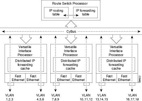
This distributed architecture allows incremental capacity increases by installation of additional VIP cards. Using VIP cards for switching the majority of IP VLAN traffic in multiprotocol environments substantially increases routing performance for the other protocols because the RSP offloads IP and can then be dedicated to switching the non-IP protocols.
VIP distributed switching offloads switching of ISL VLAN IP traffic to the VIP card, removing involvement from the main CPU. Offloading ISL traffic to the VIP card substantially improves networking performance. Because you can install multiple VIP cards in a router, VLAN routing capacity is increased linearly according to the number of VIP cards installed in the router.
To configure distributed switching on the VIP, you must first configure the router for IP routing. Perform the tasks described below in the order in which they appear.
SUMMARY STEPS
1. ![]() enable
enable
2. ![]() configure terminal
configure terminal
3. ![]() ip routing
ip routing
4. ![]() interface type slot/port-adapter/port
interface type slot/port-adapter/port
5. ![]() ip route-cache distributed
ip route-cache distributed
6. ![]() encapsulation isl vlan-identifier
encapsulation isl vlan-identifier
DETAILED STEPS
Configuring XNS Routing over ISL
XNS can be routed over VLAN subinterfaces using the ISL VLAN encapsulation protocol. The XNS Routing over ISL Virtual LANs feature provides full-feature Cisco IOS software XNS support on a per-VLAN basis, allowing standard XNS capabilities to be configured on VLANs.
To route XNS over ISL VLANs, you need to configure ISL encapsulation on the subinterface. Perform the steps described in the following task in the order in which they appear.
SUMMARY STEPS
1. ![]() enable
enable
2. ![]() configure terminal
configure terminal
3. ![]() xns routing [address]
xns routing [address]
4. ![]() interface type slot/port.subinterface-number
interface type slot/port.subinterface-number
5. ![]() encapsulation isl vlan-identifier
encapsulation isl vlan-identifier
6. ![]() xns network [number]
xns network [number]
DETAILED STEPS
Configuring CLNS Routing over ISL
CLNS can be routed over VLAN subinterfaces using the ISL VLAN encapsulation protocol. The CLNS Routing over ISL Virtual LANs feature provides full-feature Cisco IOS software CLNS support on a per-VLAN basis, allowing standard CLNS capabilities to be configured on VLANs.
To route CLNS over ISL VLANs, you need to configure ISL encapsulation on the subinterface. Perform the steps described in the following task in the order in which they appear.
SUMMARY STEPS
1. ![]() enable
enable
2. ![]() configure terminal
configure terminal
3. ![]() clns routing
clns routing
4. ![]() interface type slot/port.subinterface-number
interface type slot/port.subinterface-number
5. ![]() encapsulation isl vlan-identifier
encapsulation isl vlan-identifier
6. ![]() clns enable
clns enable
DETAILED STEPS
Configuring IS-IS Routing over ISL
IS-IS routing can be enabled over VLAN subinterfaces using the ISL VLAN encapsulation protocol. The IS-IS Routing over ISL Virtual LANs feature provides full-feature Cisco IOS software IS-IS support on a per-VLAN basis, allowing standard IS-IS capabilities to be configured on VLANs.
To enable IS-IS over ISL VLANs, you need to configure ISL encapsulation on the subinterface. Perform the steps described in the following task in the order in which they appear.
SUMMARY STEPS
1. ![]() enable
enable
2. ![]() configure terminal
configure terminal
3. ![]() router isis [tag]
router isis [tag]
4. ![]() net network-entity-title
net network-entity-title
5. ![]() interface type slot/port.subinterface-number
interface type slot/port.subinterface-number
6. ![]() encapsulation isl vlan-identifier
encapsulation isl vlan-identifier
7. ![]() clns router isis network [tag]
clns router isis network [tag]
DETAILED STEPS
Configuring Routing Between VLANs with IEEE 802.10 Encapsulation
This section describes the required and optional tasks for configuring routing between VLANs with IEEE 802.10 encapsulation.
HDLC serial links can be used as VLAN trunks in IEEE 802.10 VLANs to extend a virtual topology beyond a LAN backbone.
AppleTalk can be routed over VLAN subinterfaces using the ISL or IEEE 802.10 VLANs feature that provides full-feature Cisco IOS software AppleTalk support on a per-VLAN basis, allowing standard AppleTalk capabilities to be configured on VLANs.
AppleTalk users can now configure consolidated VLAN routing over a single VLAN trunking interface. Prior to introduction of this feature, AppleTalk could be routed only on the main interface on a LAN port. If AppleTalk routing was disabled on the main interface or if the main interface was shut down, the entire physical interface would stop routing any AppleTalk packets. With this feature enabled, AppleTalk routing on subinterfaces will be unaffected by changes in the main interface with the main interface in the "no-shut" state.
To route AppleTalk over IEEE 802.10 between VLANs, create the environment in which it will be used by customizing the subinterface and perform the tasks described in the following steps in the order in which they appear.
SUMMARY STEPS
1. ![]() enable
enable
2. ![]() configure terminal
configure terminal
3. ![]() appletalk routing [eigrp router-number]
appletalk routing [eigrp router-number]
4. ![]() interface fastethernet slot/port.subinterface-number
interface fastethernet slot/port.subinterface-number
5. ![]() appletalk cable-range cable-range [network.node]
appletalk cable-range cable-range [network.node]
6. ![]() appletalk zone zone-name
appletalk zone zone-name
7. ![]() encapsulation sde said
encapsulation sde said
DETAILED STEPS
Note ![]() For more information on configuring AppleTalk, see the "Configuring AppleTalk" module in the Cisco IOS AppleTalk Configuration Guide.
For more information on configuring AppleTalk, see the "Configuring AppleTalk" module in the Cisco IOS AppleTalk Configuration Guide.
Configuring Routing Between VLANs with IEEE 802.1Q Encapsulation
This section describes the required and optional tasks for configuring routing between VLANs with IEEE 802.1Q encapsulation. The IEEE 802.1Q protocol is used to interconnect multiple switches and routers, and for defining VLAN topologies.
Prerequisites
Configuring routing between VLANs with IEEE 802.1Q encapsulation assumes the presence of a single spanning tree and of an explicit tagging scheme with one-level tagging.
You can configure routing between any number of VLANs in your network.
Restrictions
The IEEE 802.1Q standard is extremely restrictive to untagged frames. The standard provides only a per-port VLANs solution for untagged frames. For example, assigning untagged frames to VLANs takes into consideration only the port from which they have been received. Each port has a parameter called a permanent virtual identification (Native VLAN) that specifies the VLAN assigned to receive untagged frames.
The main characteristics of the IEEE 802.1Q are that it assigns frames to VLANs by filtering and that the standard assumes the presence of a single spanning tree and of an explicit tagging scheme with one-level tagging.
This section contains the configuration tasks for each protocol supported with IEEE 802.1Q encapsulation. The basic process is the same, regardless of the protocol being routed. It involves the following tasks:
•![]() Enabling the protocol on the router
Enabling the protocol on the router
•![]() Enabling the protocol on the interface
Enabling the protocol on the interface
•![]() Defining the encapsulation format as IEEE 802.1Q
Defining the encapsulation format as IEEE 802.1Q
•![]() Customizing the protocol according to the requirements for your environment
Customizing the protocol according to the requirements for your environment
To configure IEEE 802.1Q on your network, perform the following tasks. One of the following tasks is required depending on the protocol being used.
•![]() Configuring AppleTalk Routing over IEEE 802.1Q (required)
Configuring AppleTalk Routing over IEEE 802.1Q (required)
•![]() Configuring IP Routing over IEEE 802.1Q (required)
Configuring IP Routing over IEEE 802.1Q (required)
•![]() Configuring IPX Routing over IEEE 802.1Q (required)
Configuring IPX Routing over IEEE 802.1Q (required)
The following tasks are optional. Perform the following tasks to connect a network of hosts over a simple bridging-access device to a remote access concentrator bridge between IEEE 802.1Q VLANs. The following sections contain configuration tasks for the Integrated Routing and Bridging, Transparent Bridging, and PVST+ Between VLANs with IEEE 802.1Q Encapsulation:
•![]() Configuring a VLAN for a Bridge Group with Default VLAN1 (optional)
Configuring a VLAN for a Bridge Group with Default VLAN1 (optional)
•![]() Configuring a VLAN for a Bridge Group as a Native VLAN (optional)
Configuring a VLAN for a Bridge Group as a Native VLAN (optional)
Configuring AppleTalk Routing over IEEE 802.1Q
AppleTalk can be routed over virtual LAN (VLAN) subinterfaces using the IEEE 802.1Q VLAN encapsulation protocol. AppleTalk Routing provides full-feature Cisco IOS software AppleTalk support on a per-VLAN basis, allowing standard AppleTalk capabilities to be configured on VLANs.
To route AppleTalk over IEEE 802.1Q between VLANs, you need to customize the subinterface to create the environment in which it will be used. Perform the steps in the order in which they appear.
Use the following task to enable AppleTalk routing on IEEE 802.1Q interfaces.
SUMMARY STEPS
1. ![]() enable
enable
2. ![]() configure terminal
configure terminal
3. ![]() appletalk routing [eigrp router-number]
appletalk routing [eigrp router-number]
4. ![]() interface fastethernet slot/port.subinterface-number
interface fastethernet slot/port.subinterface-number
5. ![]() encapsulation dot1q vlan-identifier
encapsulation dot1q vlan-identifier
6. ![]() appletalk cable-range cable-range [network.node]
appletalk cable-range cable-range [network.node]
7. ![]() appletalk zone zone-name
appletalk zone zone-name
DETAILED STEPS
Note ![]() For more information on configuring AppleTalk, see the "Configuring AppleTalk" module in the Cisco IOS AppleTalk Configuration Guide.
For more information on configuring AppleTalk, see the "Configuring AppleTalk" module in the Cisco IOS AppleTalk Configuration Guide.
Configuring IP Routing over IEEE 802.1Q
IP routing over IEEE 802.1Q extends IP routing capabilities to include support for routing IP frame types in VLAN configurations using the IEEE 802.1Q encapsulation.
To route IP over IEEE 802.1Q between VLANs, you need to customize the subinterface to create the environment in which it will be used. Perform the tasks described in the following sections in the order in which they appear.
SUMMARY STEPS
1. ![]() enable
enable
2. ![]() configure terminal
configure terminal
3. ![]() ip routing
ip routing
4. ![]() interface fastethernet slot/port.subinterface-number
interface fastethernet slot/port.subinterface-number
5. ![]() encapsulation dotlq vlanid
encapsulation dotlq vlanid
6. ![]() ip address ip-address mask
ip address ip-address mask
DETAILED STEPS
Once you have IP routing enabled on the router, you can customize the characteristics to suit your environment. See the appropriate Cisco IOS IP Routing Configuration Guide for the version of Cisco IOS you are using.
Configuring IPX Routing over IEEE 802.1Q
IPX routing over IEEE 802.1Q VLANs extends Novell NetWare routing capabilities to include support for routing Novell Ethernet_802.3 encapsulation frame types in VLAN configurations. Users with Novell NetWare environments can configure Novell Ethernet_802.3 encapsulation frames to be routed using IEEE 802.1Q encapsulation across VLAN boundaries.
To configure Cisco IOS software on a router with connected VLANs to exchange IPX Novell Ethernet_802.3 encapsulated frames, perform the steps described in the following task in the order in which they appear.
SUMMARY STEPS
1. ![]() enable
enable
2. ![]() configure terminal
configure terminal
3. ![]() ipx routing [node]
ipx routing [node]
4. ![]() interface fastethernet slot/port.subinterface-number
interface fastethernet slot/port.subinterface-number
5. ![]() encapsulation dotlq vlanid
encapsulation dotlq vlanid
6. ![]() ipx network network
ipx network network
DETAILED STEPS
Configuring a VLAN for a Bridge Group with Default VLAN1
Use the following task to configure a VLAN associated with a bridge group with a default native VLAN.
SUMMARY STEPS
1. ![]() enable
enable
2. ![]() configure terminal
configure terminal
3. ![]() interface fastethernet slot/port.subinterface-number
interface fastethernet slot/port.subinterface-number
4. ![]() encapsulation dotlq vlanid
encapsulation dotlq vlanid
5. ![]() bridge-group bridge-group
bridge-group bridge-group
DETAILED STEPS
Configuring a VLAN for a Bridge Group as a Native VLAN
Use the following task to configure a VLAN associated to a bridge group as a native VLAN.
SUMMARY STEPS
1. ![]() enable
enable
2. ![]() configure terminal
configure terminal
3. ![]() interface fastethernet slot/port
interface fastethernet slot/port
4. ![]() encapsulation dotlq vlanid native
encapsulation dotlq vlanid native
5. ![]() bridge-group bridge-group
bridge-group bridge-group
DETAILED STEPS
Note ![]() If there is an explicitly defined native VLAN, VLAN1 will only be used to process CST.
If there is an explicitly defined native VLAN, VLAN1 will only be used to process CST.
Configuring IEEE 802.1Q-in-Q VLAN Tag Termination
Encapsulating IEEE 802.1Q VLAN tags within 802.1Q enables service providers to use a single VLAN to support customers who have multiple VLANs. The IEEE 802.1Q-in-Q VLAN Tag Termination feature on the subinterface level preserves VLAN IDs and keeps traffic in different customer VLANs segregated.
You must have checked Feature Navigator to verify that your Cisco device and software image support this feature.
You must be connected to an Ethernet device that supports double VLAN tag imposition/disposition or switching.
The following restrictions apply to the Cisco 10000 series Internet router for configuring IEEE 802.1Q-in-Q VLAN tag termination:
•![]() Supported on Ethernet, FastEthernet, or Gigabit Ethernet interfaces.
Supported on Ethernet, FastEthernet, or Gigabit Ethernet interfaces.
•![]() Supports only Point-to-Point Protocol over Ethernet (PPPoE) packets that are double-tagged for Q-in-Q VLAN tag termination.
Supports only Point-to-Point Protocol over Ethernet (PPPoE) packets that are double-tagged for Q-in-Q VLAN tag termination.
•![]() IP and Multiprotocol Label Switching (MPLS) packets are not supported.
IP and Multiprotocol Label Switching (MPLS) packets are not supported.
•![]() Modular QoS can be applied to unambiguous subinterfaces only.
Modular QoS can be applied to unambiguous subinterfaces only.
•![]() Limited ACL support.
Limited ACL support.
Perform these tasks to configure the main interface used for the Q-in-Q double tagging and to configure the subinterfaces.
•![]() Configuring EtherType Field for Outer VLAN Tag Termination (Optional)
Configuring EtherType Field for Outer VLAN Tag Termination (Optional)
•![]() Configuring the Q-in-Q Subinterface (Required)
Configuring the Q-in-Q Subinterface (Required)
•![]() Verifying the IEEE 802.1Q-in-Q VLAN Tag Termination (Optional)
Verifying the IEEE 802.1Q-in-Q VLAN Tag Termination (Optional)
Configuring EtherType Field for Outer VLAN Tag Termination
The following restrictions are applicable for the Cisco 10000 series Internet router:
•![]() PPPoE is already configured.
PPPoE is already configured.
•![]() Virtual private dial-up network (VPDN) is enabled.
Virtual private dial-up network (VPDN) is enabled.
The first task is optional. A step in this task shows you how to configure the EtherType field to be 0x9100 for the outer VLAN tag, if that is required.
After the subinterface is defined, the 802.1Q encapsulation is configured to use the double tagging.
To configure the EtherType field for Outer VLAN Tag Termination, use the following steps. This task is optional.
SUMMARY STEPS
1. ![]() enable
enable
2. ![]() configure terminal
configure terminal
3. ![]() interface type number
interface type number
4. ![]() dot1q tunneling ethertype ethertype
dot1q tunneling ethertype ethertype
DETAILED STEPS
Configuring the Q-in-Q Subinterface
Use the following steps to configure Q-in-Q subinterfaces. This task is required.
SUMMARY STEPS
1. ![]() enable
enable
2. ![]() configure terminal
configure terminal
3. ![]() interface type number.subinterface-number
interface type number.subinterface-number
4. ![]() encapsulation dot1q vlan-id second-dot1q {any | vlan-id | vlan-id-vlan-id [,vlan-id-vlan-id]}
encapsulation dot1q vlan-id second-dot1q {any | vlan-id | vlan-id-vlan-id [,vlan-id-vlan-id]}
5. ![]() pppoe enable [group group-name]
pppoe enable [group group-name]
6. ![]() exit
exit
7. ![]() Repeat Step 3 to configure another subinterface.
Repeat Step 3 to configure another subinterface.
8. ![]() Repeat Step 4 and Step 5 to specify the VLAN tags to be terminated on the subinterface and to enable PPPoE sessions on the subinterface.
Repeat Step 4 and Step 5 to specify the VLAN tags to be terminated on the subinterface and to enable PPPoE sessions on the subinterface.
9. ![]() end
end
DETAILED STEPS
|
|
|
|
|---|---|---|
Step 1 |
enable Router> enable |
Enables privileged EXEC mode. • |
Step 2 |
configure terminal Router# configure terminal |
Enters global configuration mode. |
Step 3 |
interface type number.subinterface-number Router(config)# interface gigabitethernet 1/0/0.1 |
Configures a subinterface and enters subinterface configuration mode. |
Step 4 |
encapsulation dot1q vlan-id second-dot1q {any | vlan-id | vlan-id-vlan-id [,vlan-id-vlan-id]} Router(config-subif)# encapsulation dot1q 100 second-dot1q 200 |
(Required) Enables the 802.1Q encapsulation of traffic on a specified subinterface in a VLAN. • • • |
Step 5 |
pppoe enable [group group-name] Router(config-subif)# pppoe enable group vpn1 |
Enables PPPoE sessions on a subinterface. • |
Step 6 |
exit Router(config-subif)# exit |
Exits subinterface configuration mode and returns to interface configuration mode. • |
Step 7 |
Repeat Step 3 to configure another subinterface. Router(config-if)# interface gigabitethernet 1/0/0.2 |
(Optional) Configures a subinterface and enters subinterface configuration mode. |
Step 8 |
Repeat Step 4 and Step 5 to specify the VLAN tags to be terminated on the subinterface. Router(config-subif)# encapsulation dot1q 100 second-dot1q 100-199,201-600 Router(config-subif)# pppoe enable group vpn1 |
Step 4 enables the 802.1Q encapsulation of traffic on a specified subinterface in a VLAN. • • • Step 5 enables PPPoE sessions on the subinterface. The example specifies that the PPPoE profile, vpn1, will be used by PPPoE sessions on the subinterface. Note |
Step 9 |
end Router(config-subif)# end |
Exits subinterface configuration mode and returns to privileged EXEC mode. |
Verifying the IEEE 802.1Q-in-Q VLAN Tag Termination
Perform this optional task to verify the configuration of the IEEE 802.1Q-in-Q VLAN Tag Termination feature.
SUMMARY STEPS
1. ![]() enable
enable
2. ![]() show running-config
show running-config
3. ![]() show vlans dot1q [internal | interface-type interface-number.subinterface-number [detail] | outer-id [interface-type interface-number | second-dot1q [inner-id | any]] [detail]]
show vlans dot1q [internal | interface-type interface-number.subinterface-number [detail] | outer-id [interface-type interface-number | second-dot1q [inner-id | any]] [detail]]
DETAILED STEPS
Step 1 ![]() enable
enable
Enables privileged EXEC mode. Enter your password if prompted.
Router> enable
Step 2 ![]() show running-config
show running-config
Use this command to show the currently running configuration on the device. You can use delimiting characters to display only the relevant parts of the configuration.
The following shows the currently running configuration on a Cisco 7300 series router:
Router# show running-config
.
.
.
interface FastEthernet0/0.201
encapsulation dot1Q 201
ip address 10.7.7.5 255.255.255.252
!
interface FastEthernet0/0.401
encapsulation dot1Q 401
ip address 10.7.7.13 255.255.255.252
!
interface FastEthernet0/0.201999
encapsulation dot1Q 201 second-dot1q any
pppoe enable
!
interface FastEthernet0/0.2012001
encapsulation dot1Q 201 second-dot1q 2001
ip address 10.8.8.9 255.255.255.252
!
interface FastEthernet0/0.2012002
encapsulation dot1Q 201 second-dot1q 2002
ip address 10.8.8.13 255.255.255.252
!
interface FastEthernet0/0.4019999
encapsulation dot1Q 401 second-dot1q 100-900,1001-2000
pppoe enable
!
interface GigabitEthernet5/0.101
encapsulation dot1Q 101
ip address 10.7.7.1 255.255.255.252
!
interface GigabitEthernet5/0.301
encapsulation dot1Q 301
ip address 10.7.7.9 255.255.255.252
!
interface GigabitEthernet5/0.301999
encapsulation dot1Q 301 second-dot1q any
pppoe enable
!
interface GigabitEthernet5/0.1011001
encapsulation dot1Q 101 second-dot1q 1001
ip address 10.8.8.1 255.255.255.252
!
interface GigabitEthernet5/0.1011002
encapsulation dot1Q 101 second-dot1q 1002
ip address 10.8.8.5 255.255.255.252
!
interface GigabitEthernet5/0.1019999
encapsulation dot1Q 101 second-dot1q 1-1000,1003-2000
pppoe enable
.
.
.
The following shows the currently running configuration on a Cisco 10000 series Internet router:
Router# show running-config
.
.
.
interface FastEthernet1/0/0.201
encapsulation dot1Q 201
ip address 10.7.7.5 255.255.255.252
!
interface FastEthernet1/0/0.401
encapsulation dot1Q 401
ip address 10.7.7.13 255.255.255.252
!
interface FastEthernet1/0/0.201999
encapsulation dot1Q 201 second-dot1q any
pppoe enable
!
interface FastEthernet1/0/0.4019999
encapsulation dot1Q 401 second-dot1q 100-900,1001-2000
pppoe enable
!
interface GigabitEthernet5/0/0.101
encapsulation dot1Q 101
ip address 10.7.7.1 255.255.255.252
!
interface GigabitEthernet5/0/0.301
encapsulation dot1Q 301
ip address 10.7.7.9 255.255.255.252
!
interface GigabitEthernet5/0/0.301999
encapsulation dot1Q 301 second-dot1q any
pppoe enable
!
interface GigabitEthernet5/0/0.1019999
encapsulation dot1Q 101 second-dot1q 1-1000,1003-2000
pppoe enable
.
.
.
Step 3 ![]() show vlans dot1q [internal | interface-type interface-number.subinterface-number [detail] | outer-id [interface-type interface-number | second-dot1q [inner-id | any]] [detail]]
show vlans dot1q [internal | interface-type interface-number.subinterface-number [detail] | outer-id [interface-type interface-number | second-dot1q [inner-id | any]] [detail]]
Use this command to show the statistics for all the 802.1Q VLAN IDs. In this example, only the outer VLAN ID is displayed.
Note ![]() The show vlans dot1q command is not supported on the Cisco 10000 series Internet router.
The show vlans dot1q command is not supported on the Cisco 10000 series Internet router.
Router# show vlans dot1q
Total statistics for 802.1Q VLAN 1:
441 packets, 85825 bytes input
1028 packets, 69082 bytes output
Total statistics for 802.1Q VLAN 101:
5173 packets, 510384 bytes input
3042 packets, 369567 bytes output
Total statistics for 802.1Q VLAN 201:
1012 packets, 119254 bytes input
1018 packets, 120393 bytes output
Total statistics for 802.1Q VLAN 301:
3163 packets, 265272 bytes input
1011 packets, 120750 bytes output
Total statistics for 802.1Q VLAN 401:
1012 packets, 119254 bytes input
1010 packets, 119108 bytes output
Monitoring and Maintaining VLAN Subinterfaces
Use the following task to determine whether a VLAN is a native VLAN.
SUMMARY STEPS
1. ![]() enable
enable
2. ![]() show vlans
show vlans
DETAILED STEPS
Monitoring and Maintaining VLAN Subinterfaces: Example
The following is sample output from the show vlans command indicating a native VLAN and a bridged group:
Router# show vlans
Virtual LAN ID: 1 (IEEE 802.1Q Encapsulation)
vLAN Trunk Interface: FastEthernet1/0/2
This is configured as native Vlan for the following interface(s) :
FastEthernet1/0/2
Protocols Configured: Address: Received: Transmitted:
Virtual LAN ID: 100 (IEEE 802.1Q Encapsulation)
vLAN Trunk Interface: FastEthernet1/0/2.1
Protocols Configured: Address: Received: Transmitted:
Bridging Bridge Group 1 0 0
The following is sample output from the show vlans command that shows the traffic count on Fast Ethernet subinterfaces:
Router# show vlans
Virtual LAN ID: 2 (IEEE 802.1Q Encapsulation)
vLAN Trunk Interface: FastEthernet5/0.1
Protocols Configured: Address: Received: Transmitted:
IP 172.16.0.3 16 92129
Virtual LAN ID: 3 (IEEE 802.1Q Encapsulation)
vLAN Trunk Interface: Ethernet6/0/1.1
Protocols Configured: Address: Received: Transmitted:
IP 172.20.0.3 1558 1521
Virtual LAN ID: 4 (Inter Switch Link Encapsulation)
vLAN Trunk Interface: FastEthernet5/0.2
Protocols Configured: Address: Received: Transmitted:
IP 172.30.0.3 0 7
Configuration Examples for Configuring Routing Between VLANs
•![]() Single Range Configuration: Example
Single Range Configuration: Example
•![]() ISL Encapsulation Configuration: Examples
ISL Encapsulation Configuration: Examples
•![]() Routing IEEE 802.10 Configuration: Example
Routing IEEE 802.10 Configuration: Example
•![]() IEEE 802.1Q Encapsulation Configuration: Examples
IEEE 802.1Q Encapsulation Configuration: Examples
•![]() Configuring IEEE 802.1Q-in-Q VLAN Tag Termination: Example
Configuring IEEE 802.1Q-in-Q VLAN Tag Termination: Example
Single Range Configuration: Example
The following example configures the Fast Ethernet subinterfaces within the range 5/1.1 and 5/1.4 and applies the following VLAN IDs to those subinterfaces:
Fast Ethernet5/1.1 = VLAN ID 301 (vlan-id)
Fast Ethernet5/1.2 = VLAN ID 302 (vlan-id = 301 + 2 - 1 = 302)
Fast Ethernet5/1.3 = VLAN ID 303 (vlan-id = 301 + 3 - 1 = 303)
Fast Ethernet5/1.4 = VLAN ID 304 (vlan-id = 301 + 4 - 1 = 304)
Router(config)# interface range fastethernet5/1.1 - fastethernet5/1.4
Router(config-if)# encapsulation dot1Q 301
Router(config-if)# no shutdown
Router(config-if)#
*Oct 6 08:24:35: %LINK-3-UPDOWN: Interface FastEthernet5/1.1, changed state to up
*Oct 6 08:24:35: %LINK-3-UPDOWN: Interface FastEthernet5/1.2, changed state to up
*Oct 6 08:24:35: %LINK-3-UPDOWN: Interface FastEthernet5/1.3, changed state to up
*Oct 6 08:24:35: %LINK-3-UPDOWN: Interface FastEthernet5/1.4, changed state to up
*Oct  6 08:24:36: %LINEPROTO-5-UPDOWN: Line protocol on Interface FastEthernet5/1.1,
changed state to up
*Oct  6 08:24:36: %LINEPROTO-5-UPDOWN: Line protocol on Interface FastEthernet5/1.2,
changed state to up
*Oct  6 08:24:36: %LINEPROTO-5-UPDOWN: Line protocol on Interface FastEthernet5/1.3,
changed state to up
*Oct  6 08:24:36: %LINEPROTO-5-UPDOWN: Line protocol on Interface FastEthernet5/1.4,
changed state to up
ISL Encapsulation Configuration: Examples
This section provides the following configuration examples for each of the protocols described in this module:
•![]() AppleTalk Routing over ISL Configuration: Example
AppleTalk Routing over ISL Configuration: Example
•![]() Banyan VINES Routing over ISL Configuration: Example
Banyan VINES Routing over ISL Configuration: Example
•![]() DECnet Routing over ISL Configuration: Example
DECnet Routing over ISL Configuration: Example
•![]() HSRP over ISL Configuration: Example
HSRP over ISL Configuration: Example
•![]() IP Routing with RIF Between TrBRF VLANs: Example
IP Routing with RIF Between TrBRF VLANs: Example
•![]() IP Routing Between a TRISL VLAN and an Ethernet ISL VLAN: Example
IP Routing Between a TRISL VLAN and an Ethernet ISL VLAN: Example
•![]() IPX Routing over ISL Configuration: Example
IPX Routing over ISL Configuration: Example
•![]() IPX Routing on FDDI Interfaces with SDE: Example
IPX Routing on FDDI Interfaces with SDE: Example
•![]() Routing with RIF Between a TRISL VLAN and a Token Ring Interface: Example
Routing with RIF Between a TRISL VLAN and a Token Ring Interface: Example
•![]() VIP Distributed Switching over ISL Configuration: Example
VIP Distributed Switching over ISL Configuration: Example
•![]() XNS Routing over ISL Configuration: Example
XNS Routing over ISL Configuration: Example
•![]() CLNS Routing over ISL Configuration: Example
CLNS Routing over ISL Configuration: Example
•![]() IS-IS Routing over ISL Configuration: Example
IS-IS Routing over ISL Configuration: Example
AppleTalk Routing over ISL Configuration: Example
The configuration example illustrated in Figure 12 shows AppleTalk being routed between different ISL and IEEE 802.10 VLAN encapsulating subinterfaces.
Figure 12 Routing AppleTalk over VLAN Encapsulations
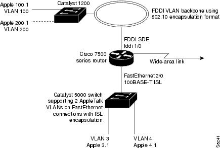
As shown in Figure 12, AppleTalk traffic is routed to and from switched VLAN domains 3, 4, 100, and 200 to any other AppleTalk routing interface. This example shows a sample configuration file for the Cisco 7500 series router with the commands entered to configure the network shown in Figure 12.
Cisco 7500 Router Configuration
!
appletalk routing
interface Fddi 1/0.100
encapsulation sde 100
appletalk cable-range 100-100 100.2
appletalk zone 100
!
interface Fddi 1/0.200
encapsulation sde 200
appletalk cable-range 200-200 200.2
appletalk zone 200
!
interface FastEthernet 2/0.3
encapsulation isl 3
appletalk cable-range 3-3 3.2
appletalk zone 3
!
interface FastEthernet 2/0.4
encapsulation isl 4
appletalk cable-range 4-4 4.2
appletalk zone 4
!
Banyan VINES Routing over ISL Configuration: Example
To configure routing of the Banyan VINES protocol over ISL trunks, you need to define ISL as the encapsulation type. This example shows Banyan VINES configured to be routed over an ISL trunk:
vines routing
interface fastethernet 0.1
encapsulation isl 100
vines metric 2
DECnet Routing over ISL Configuration: Example
To configure routing the DECnet protocol over ISL trunks, you need to define ISL as the encapsulation type. This example shows DECnet configured to be routed over an ISL trunk:
decnet routing 2.1
interface fastethernet 1/0.1
encapsulation isl 200
decnet cost 4
HSRP over ISL Configuration: Example
The configuration example shown in Figure 13 shows HSRP being used on two VLAN routers sending traffic to and from ISL VLANs through a Catalyst 5000 switch. Each router forwards its own traffic and acts as a standby for the other.
Figure 13 Hot Standby Router Protocol Sample Configuration
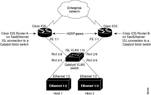
The topology shown in Figure 13 shows a Catalyst VLAN switch supporting Fast Ethernet connections to two routers running HSRP. Both routers are configured to route HSRP over ISLs.
The standby conditions are determined by the standby commands used in the configuration. Traffic from Host 1 is forwarded through Router A. Because the priority for the group is higher, Router A is the active router for Host 1. Because the priority for the group serviced by Host 2 is higher in Router B, traffic from Host 2 is forwarded through Router B, making Router B its active router.
In the configuration shown in Figure 13, if the active router becomes unavailable, the standby router assumes active status for the additional traffic and automatically routes the traffic normally handled by the router that has become unavailable.
Host 1 Configuration
interface Ethernet 1/2
ip address 10.1.1.25 255.255.255.0
ip route 0.0.0.0 0.0.0.0 10.1.1.101
Host 2 Configuration
interface Ethernet 1/2
ip address 10.1.1.27 255.255.255.0
ip route 0.0.0.0 0.0.0.0 10.1.1.102
!
Router A Configuration
interface FastEthernet 1/1.110
encapsulation isl 110
ip address 10.1.1.2 255.255.255.0
standby 1 ip 10.1.1.101
standby 1 preempt
standby 1 priority 105
standby 2 ip 10.1.1.102
standby 2 preempt
!
end
!
Router B Configuration
interface FastEthernet 1/1.110
encapsulation isl 110
ip address 10.1.1.3 255.255.255.0
standby 1 ip 10.1.1.101
standby 1 preempt
standby 2 ip 10.1.1.102
standby 2 preempt
standby 2 priority 105
router igrp 1
!
network 10.1.0.0
network 10.2.0.0
!
VLAN Switch Configuration
set vlan 110 5/4
set vlan 110 5/3
set trunk 2/8 110
set trunk 2/9 110
IP Routing with RIF Between TrBRF VLANs: Example
Figure 14 shows IP routing with RIF between two TrBRF VLANs.
Figure 14 IP Routing with RIF Between TrBRF VLANs
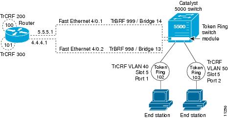
The following is the configuration for the router:
interface FastEthernet4/0.1
ip address 10.5.5.1 255.255.255.0
encapsulation tr-isl trbrf-vlan 999 bridge-num 14
multiring trcrf-vlan 200 ring 100
multiring all
!
interface FastEthernet4/0.2
ip address 10.4.4.1 255.255.255.0
encapsulation tr-isl trbrf-vlan 998 bridge-num 13
multiring trcrf-vlan 300 ring 101
multiring all
The following is the configuration for the Catalyst 5000 switch with the Token Ring switch module in slot 5. In this configuration, the Token Ring port 102 is assigned with TrCRF VLAN 40 and the Token Ring port 103 is assigned with TrCRF VLAN 50:
#vtp
set vtp domain trisl
set vtp mode server
set vtp v2 enable
#drip
set set tokenring reduction enable
set tokenring distrib-crf disable
#vlans
set vlan 999 name trbrf type trbrf bridge 0xe stp ieee
set vlan 200 name trcrf200 type trcrf parent 999 ring 0x64 mode srb
set vlan 40 name trcrf40 type trcrf parent 999 ring 0x66 mode srb
set vlan 998 name trbrf type trbrf bridge 0xd stp ieee
set vlan 300 name trcrf300 type trcrf parent 998 ring 0x65 mode srb
set vlan 50 name trcrf50 type trcrf parent 998 ring 0x67 mode srb
#add token port to trcrf 40
set vlan 40 5/1
#add token port to trcrf 50
set vlan 50 5/2
set trunk 1/2 on
IP Routing Between a TRISL VLAN and an Ethernet ISL VLAN: Example
Figure 15 shows IP routing between a TRISL VLAN and an Ethernet ISL VLAN.
Figure 15 IP Routing Between a TRISL VLAN and an Ethernet ISL VLAN
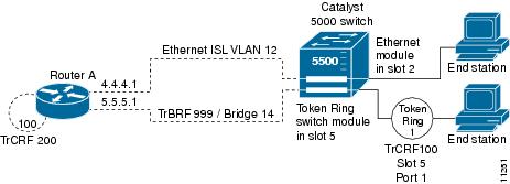
The following is the configuration for the router:
interface FastEthernet4/0.1
ip address 10.5.5.1 255.255.255.0
encapsulation tr-isl trbrf-vlan 999 bridge-num 14
multiring trcrf-vlan 20 ring 100
multiring all
!
interface FastEthernet4/0.2
ip address 10.4.4.1 255.255.255.0
encapsulation isl 12
IPX Routing over ISL Configuration: Example
Figure 16 shows IPX interior encapsulations configured over ISL encapsulation in VLAN configurations. Note that three different IPX encapsulation formats are used. VLAN 20 uses SAP encapsulation, VLAN 30 uses ARPA, and VLAN 70 uses novell-ether encapsulation. Prior to the introduction of this feature, only the default encapsulation format, "novell-ether," was available for routing IPX over ISL links in VLANs.
Figure 16 Configurable IPX Encapsulations Routed over ISL in VLAN Configurations
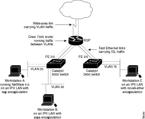
VLAN 20 Configuration
ipx routing
interface FastEthernet 2/0
no shutdown
interface FastEthernet 2/0.20
encapsulation isl 20
ipx network 20 encapsulation sap
VLAN 30 Configuration
ipx routing
interface FastEthernet 2/0
no shutdown
interface FastEthernet 2/0.30
encapsulation isl 30
ipx network 30 encapsulation arpa
VLAN 70 Configuration
ipx routing
interface FastEthernet 3/0
no shutdown
interface Fast3/0.70
encapsulation isl 70
ipx network 70 encapsulation novell-ether
IPX Routing on FDDI Interfaces with SDE: Example
The following example enables IPX routing on FDDI interfaces 0.2 and 0.3 with SDE. On FDDI interface 0.2, the encapsulation type is SNAP. On FDDI interface 0.3, the encapsulation type is Novell's FDDI_RAW.
ipx routing
interface fddi 0.2 enc sde 2
ipx network f02 encapsulation snap
interface fddi 0.3 enc sde 3
ipx network f03 encapsulation novell-fddi
Routing with RIF Between a TRISL VLAN and a Token Ring Interface: Example
Figure 17 shows routing with RIF between a TRISL VLAN and a Token Ring interface.
Figure 17 Routing with RIF Between a TRISL VLAN and a Token Ring Interface
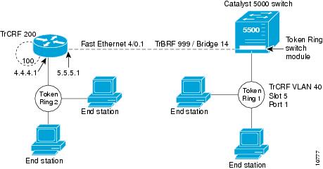
The following is the configuration for the router:
source-bridge ring-group 100
!
interface TokenRing 3/1
ip address 10.4.4.1 255.255.255.0
!
interface FastEthernet4/0.1
ip address 10.5.5.1 255.255.255.0
encapsulation tr-isl trbrf 999 bridge-num 14
multiring trcrf-vlan 200 ring-group 100
multiring all
The following is the configuration for the Catalyst 5000 switch with the Token Ring switch module in slot 5. In this configuration, the Token Ring port 1 is assigned to the TrCRF VLAN 40:
#vtp
set vtp domain trisl
set vtp mode server
set vtp v2 enable
#drip
set set tokenring reduction enable
set tokenring distrib-crf disable
#vlans
set vlan 999 name trbrf type trbrf bridge 0xe stp ieee
set vlan 200 name trcrf200 type trcrf parent 999 ring 0x64 mode srt
set vlan 40 name trcrf40 type trcrf parent 999 ring 0x1 mode srt
#add token port to trcrf 40
set vlan 40 5/1
set trunk 1/2 on
VIP Distributed Switching over ISL Configuration: Example
Figure 18 shows a topology in which Catalyst VLAN switches are connected to routers forwarding traffic from a number of ISL VLANs. With the VIP distributed ISL capability in the Cisco 7500 series router, each VIP card can route ISL-encapsulated VLAN IP traffic. The inter-VLAN routing capacity is increased linearly by the packet-forwarding capability of each VIP card.
Figure 18 VIP Distributed ISL VLAN Traffic
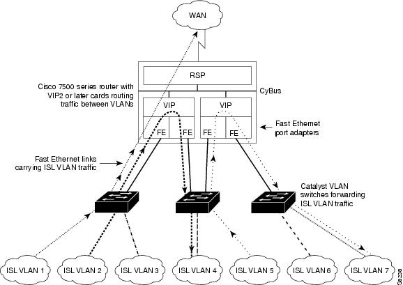
In Figure 18, the VIP cards forward the traffic between ISL VLANs or any other routing interface. Traffic from any VLAN can be routed to any of the other VLANs, regardless of which VIP card receives the traffic.
These commands show the configuration for each of the VLANs shown in Figure 18:
interface FastEthernet1/0/0
ip address 10.1.1.1 255.255.255.0
ip route-cache distributed
full-duplex
interface FastEthernet1/0/0.1
ip address 10.1.1.1 255.255.255.0
encapsulation isl 1
interface FastEthernet1/0/0.2
ip address 10.1.2.1 255.255.255.0
encapsulation isl 2
interface FastEthernet1/0/0.3
ip address 10.1.3.1 255.255.255.0
encapsulation isl 3
interface FastEthernet1/1/0
ip route-cache distributed
full-duplex
interface FastEthernet1/1/0.1
ip address 172.16.1.1 255.255.255.0
encapsulation isl 4
interface Fast Ethernet 2/0/0
ip address 10.1.1.1 255.255.255.0
ip route-cache distributed
full-duplex
interface FastEthernet2/0/0.5
ip address 10.2.1.1 255.255.255.0
encapsulation isl 5
interface FastEthernet2/1/0
ip address 10.3.1.1 255.255.255.0
ip route-cache distributed
full-duplex
interface FastEthernet2/1/0.6
ip address 10.4.6.1 255.255.255.0
encapsulation isl 6
interface FastEthernet2/1/0.7
ip address 10.4.7.1 255.255.255.0
encapsulation isl 7
XNS Routing over ISL Configuration: Example
To configure routing of the XNS protocol over ISL trunks, you need to define ISL as the encapsulation type. This example shows XNS configured to be routed over an ISL trunk:
xns routing 0123.4567.adcb
interface fastethernet 1/0.1
encapsulation isl 100
xns network 20
CLNS Routing over ISL Configuration: Example
To configure routing of the CLNS protocol over ISL trunks, you need to define ISL as the encapsulation type. This example shows CLNS configured to be routed over an ISL trunk:
clns routing
interface fastethernet 1/0.1
encapsulation isl 100
clns enable
IS-IS Routing over ISL Configuration: Example
To configure IS-IS routing over ISL trunks, you need to define ISL as the encapsulation type. This example shows IS-IS configured over an ISL trunk:
isis routing test-proc2
net 49.0001.0002.aaaa.aaaa.aaaa.00
interface fastethernet 2.0
encapsulation isl 101
clns router is-is test-proc2
Routing IEEE 802.10 Configuration: Example
The configuration example shown in Figure 19 shows AppleTalk being routed between different ISL and IEEE 802.10 VLAN encapsulating subinterfaces.
Figure 19 Routing AppleTalk over VLAN encapsulations
As shown in Figure 19, AppleTalk traffic is routed to and from switched VLAN domains 3, 4, 100, and 200 to any other AppleTalk routing interface. This example shows a sample configuration file for the Cisco 7500 series router with the commands entered to configure the network shown in Figure 19.
Cisco 7500 Router Configuration
!
interface Fddi 1/0.100
encapsulation sde 100
appletalk cable-range 100-100 100.2
appletalk zone 100
!
interface Fddi 1/0.200
encapsulation sde 200
appletalk cable-range 200-200 200.2
appletalk zone 200
!
interface FastEthernet 2/0.3
encapsulation isl 3
appletalk cable-range 3-3 3.2
appletalk zone 3
!
interface FastEthernet 2/0.4
encapsulation isl 4
appletalk cable-range 4-4 4.2
appletalk zone 4
!
IEEE 802.1Q Encapsulation Configuration: Examples
Configuration examples for each protocols are provided in the following sections:
•![]() !Configuring AppleTalk over IEEE 802.1Q: Example
!Configuring AppleTalk over IEEE 802.1Q: Example
•![]() Configuring IP Routing over IEEE 802.1Q: Example
Configuring IP Routing over IEEE 802.1Q: Example
•![]() Configuring IPX Routing over IEEE 802.1Q: Example
Configuring IPX Routing over IEEE 802.1Q: Example
•![]() VLAN 100 for Bridge Group 1 with Default VLAN1: Example
VLAN 100 for Bridge Group 1 with Default VLAN1: Example
•![]() VLAN 20 for Bridge Group 1 with Native VLAN: Example
VLAN 20 for Bridge Group 1 with Native VLAN: Example
•![]() VLAN ISL or IEEE 802.1Q Routing: Example
VLAN ISL or IEEE 802.1Q Routing: Example
•![]() VLAN IEEE 802.1Q Bridging: Example
VLAN IEEE 802.1Q Bridging: Example
•![]() VLAN IEEE 802.1Q IRB: Example
VLAN IEEE 802.1Q IRB: Example
Configuring AppleTalk over IEEE 802.1Q: Example
This configuration example shows AppleTalk being routed on VLAN 100:
!
appletalk routing
!
interface fastethernet 4/1.100
encapsulation dot1q 100
appletalk cable-range 100-100 100.1
appletalk zone eng
!
Configuring IP Routing over IEEE 802.1Q: Example
This configuration example shows IP being routed on VLAN 101:
!
ip routing
!
interface fastethernet 4/1.101
encapsulation dot1q 101
ip addr 10.0.0.11 255.0.0.0
!
Configuring IPX Routing over IEEE 802.1Q: Example
This configuration example shows IPX being routed on VLAN 102:
!
ipx routing
!
interface fastethernet 4/1.102
encapsulation dot1q 102
ipx network 100
!
VLAN 100 for Bridge Group 1 with Default VLAN1: Example
The following example configures VLAN 100 for bridge group 1 with a default VLAN1:
interface FastEthernet 4/1.100
encapsulation dot1q 1
bridge-group 1
VLAN 20 for Bridge Group 1 with Native VLAN: Example
The following example configures VLAN 20 for bridge group 1 as a native VLAN:
interface FastEthernet 4/1.100
encapsulation dot1q 20 native
bridge-group 1
VLAN ISL or IEEE 802.1Q Routing: Example
The following example configures VLAN ISL or IEEE 802.10 routing:
ipx routing
appletalk routing
!
interface Ethernet 1
ip address 10.1.1.1 255.255.255.0
appletalk cable-range 1-1 1.1
appletalk zone 1
ipx network 10 encapsulation snap
!
router igrp 1
network 10.1.0.0
!
end
!
#Catalyst5000
!
set VLAN 110 2/1
set VLAN 120 2/2
!
set trunk 1/1 110,120
# if 802.1Q, set trunk 1/1 nonegotiate 110, 120
!
end
!
ipx routing
appletalk routing
!
interface FastEthernet 1/1.110
encapsulation isl 110
!if 802.1Q, encapsulation dot1Q 110
ip address 10.1.1.2 255.255.255.0
appletalk cable-range 1.1 1.2
appletalk zone 1
ipx network 110 encapsulation snap
!
interface FastEthernet 1/1.120
encapsulation isl 120
!if 802.1Q, encapsulation dot1Q 120
ip address 10.2.1.2 255.255.255.0
appletalk cable-range 2-2 2.2
appletalk zone 2
ipx network 120 encapsulation snap
!
router igrp 1
network 10.1.0.0
network 10.2.1.0.0
!
end
!
ipx routing
appletalk routing
!
interface Ethernet 1
ip address 10.2.1.3 255.255.255.0
appletalk cable-range 2-2 2.3
appletalk zone 2
ipx network 120 encapsulation snap
!
router igrp 1
network 10.2.0.0
!
end
VLAN IEEE 802.1Q Bridging: Example
The following examples configures IEEE 802.1Q bridging:
interface FastEthernet4/0
no ip address
no ip route-cache
half-duplex
!
interface FastEthernet4/0.100
encapsulation dot1Q 100
no ip route-cache
bridge-group 1
!
interface FastEthernet4/0.200
encapsulation dot1Q 200 native
no ip route-cache
bridge-group 2
!
interface FastEthernet4/0.300
encapsulation dot1Q 1
no ip route-cache
bridge-group 3
!
interface FastEthernet10/0
no ip address
no ip route-cache
half-duplex
!
interface FastEthernet10/0.100
encapsulation dot1Q 100
no ip route-cache
bridge-group 1
!
interface Ethernet11/3
no ip address
no ip route-cache
bridge-group 2
!
interface Ethernet11/4
no ip address
no ip route-cache
bridge-group 3
!
bridge 1 protocol ieee
bridge 2 protocol ieee
bridge 3 protocol ieee
VLAN IEEE 802.1Q IRB: Example
The following examples configures IEEE 802.1Q integrated routing and bridging:
ip cef
appletalk routing
ipx routing 0060.2f27.5980
!
bridge irb
!
interface TokenRing3/1
no ip address
ring-speed 16
bridge-group 2
!
interface FastEthernet4/0
no ip address
half-duplex
!
interface FastEthernet4/0.100
encapsulation dot1Q 100
bridge-group 1
!
interface FastEthernet4/0.200
encapsulation dot1Q 200
bridge-group 2
!
interface FastEthernet10/0
ip address 10.3.1.10 255.255.255.0
half-duplex
appletalk cable-range 200-200 200.10
appletalk zone irb
ipx network 200
!
interface Ethernet11/3
no ip address
bridge-group 1
!
interface BVI 1
ip address 10.1.1.11 255.255.255.0
appletalk cable-range 100-100 100.11
appletalk zone bridging
ipx network 100
!
router rip
network 10.0.0.0
network 10.3.0.0
!
bridge 1 protocol ieee
bridge 1 route appletalk
bridge 1 route ip
bridge 1 route ipx
bridge 2 protocol ieee
!
Configuring IEEE 802.1Q-in-Q VLAN Tag Termination: Example
Some ambiguous subinterfaces can use the any keyword for the inner VLAN ID specification. The any keyword represents any inner VLAN ID that is not explicitly configured on any other interface. In the following example, seven subinterfaces are configured with various outer and inner VLAN IDs.
Note ![]() The any keyword can be configured on only one subinterface of a specified physical interface and outer VLAN ID.
The any keyword can be configured on only one subinterface of a specified physical interface and outer VLAN ID.
interface GigabitEthernet1/0/0.1
encapsulation dot1q 100 second-dot1q 100
interface GigabitEthernet1/0/0.2
encapsulation dot1q 100 second-dot1q 200
interface GigabitEthernet1/0/0.3
encapsulation dot1q 100 second-dot1q 300-400,500-600
interface GigabitEthernet1/0/0.4
encapsulation dot1q 100 second-dot1q any
interface GigabitEthernet1/0/0.5
encapsulation dot1q 200 second-dot1q 50
interface GigabitEthernet1/0/0.6
encapsulation dot1q 200 second-dot1q 1000-2000,3000-4000
interface GigabitEthernet1/0/0.7
encapsulation dot1q 200 second-dot1q any
Table 2 shows which subinterfaces are mapped to different values of the outer and inner VLAN ID on Q-in-Q frames that come in on Gigabit Ethernet interface 1/0/0.
A new subinterface is now configured:
interface GigabitEthernet1/0/0.8
encapsulation dot1q 200 second-dot1q 200-600,900-999
Table 3 shows the changes made to the table for the outer VLAN ID of 200. Notice that subinterface 1/0/0.7 configured with the any keyword now has new inner VLAN ID mappings.
Additional References
The following sections provide references related to configuring a VLAN range.
Related Documents
|
|
|
|---|---|
IP LAN switching commands: complete command syntax, command mode, defaults, usage guidelines, and examples |
|
SNMP |
"Configuring SNMP Support" module in the Cisco IOS Network Management Configuration Guide |
HSRP |
"Configuring HSRP" module in the Cisco IOS IP Application Services Configuration Guide |
Encapsulation types and corresponding framing types |
"Configuring Novell IPX" module in the Cisco IOS Novell IPX Configuration Guide |
AppleTalk |
"Configuring AppleTalk" module in the Cisco IOS AppleTalk Configuration Guide |
Standards
|
|
|
|---|---|
IEEE 802.10 standard |
802.10 Virtual LANs |
MIBs
RFCs
|
|
|
|---|---|
No new or modified RFCs are supported by this feature, and support for existing standards has not been modified by this feature. |
— |
Technical Assistance
Feature Information for Routing Between VLANs
Table 4 lists the release history for this feature.
Not all commands may be available in your Cisco IOS software release. For release information about a specific command, see the command reference documentation.
Use Cisco Feature Navigator to find information about platform support and software image support. Cisco Feature Navigator enables you to determine which Cisco IOS and Catalyst OS software images support a specific software release, feature set, or platform. To access Cisco Feature Navigator, go to http://www.cisco.com/go/cfn. An account on Cisco.com is not required.
Note ![]() Table 4 lists only the Cisco IOS software release that introduced support for a given feature in a given Cisco IOS software release. Unless noted otherwise, subsequent releases of that Cisco IOS software also support that feature.
Table 4 lists only the Cisco IOS software release that introduced support for a given feature in a given Cisco IOS software release. Unless noted otherwise, subsequent releases of that Cisco IOS software also support that feature.
 Feedback